

Page 1
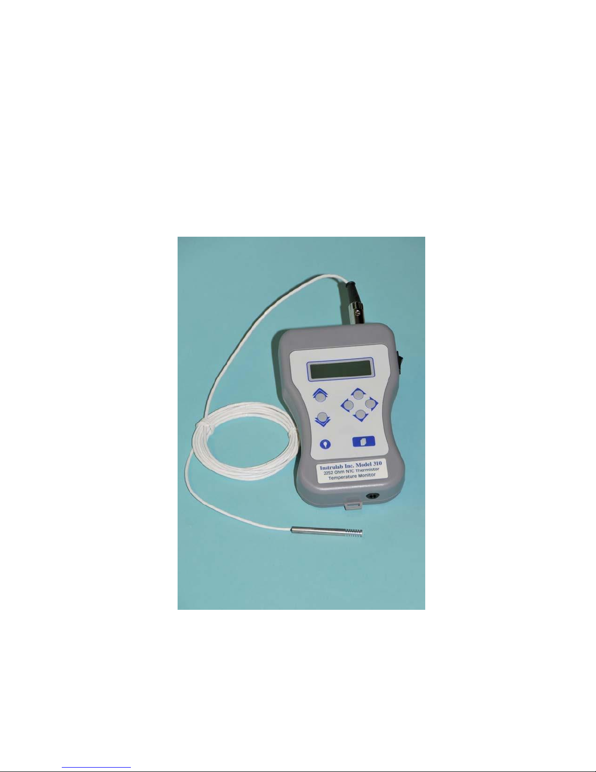
Model 310
Operator’s Manual
Page 2

Page 3

Page 4

Page 5

Model 310
Table of Contents
Section 1: Setup ..............................................................................2
Section 2: Model 310 Calibration .................................................10
Section 3: Data Page.....................................................................11
Section 4: Remote Operation.......................................................13
Section 5: Specifications..............................................................16
Section 6: Features
.......................................................................17Section 7: Select
and Use Feature...............................................18
Page 1of 18 Jun10
Page 6
Secton 1 Setup
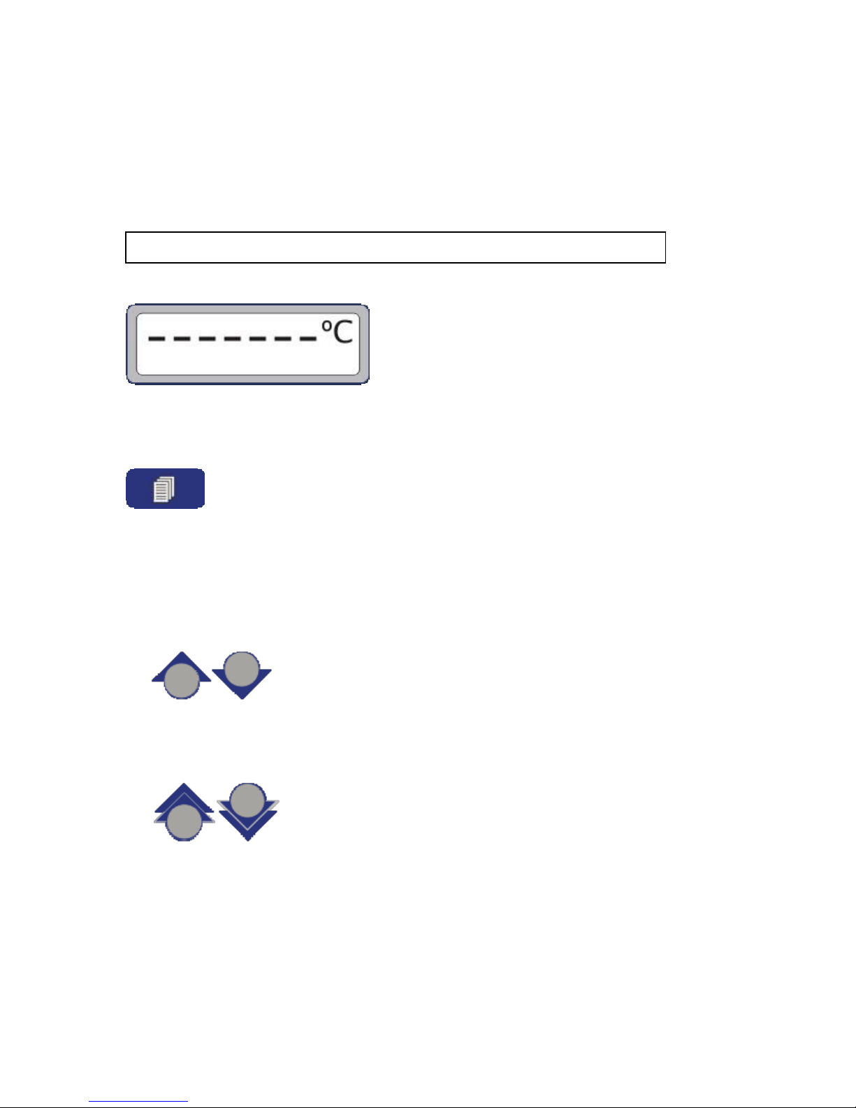
The Data Page is displayed each time the Model 310 is powered on. To display the Setup Pages,
press the Setup key.
General Setup Navigation
• To change Setup pages or highlight a different parameter, press either the “single” Up or
“single” Down arrow key.
• To change the value of a scrollable parameter (e.g., Units), press either the “single” Up or
“single” Down arrow key.
• To change the value of an editable parameter (e.g., Rtp), position the cursor with the Left or
Right arrow key
Page 2 of 18 Aug 08
Page 7
Model 310
and scroll the digit (or character) with either the “double” Up or “doublee” Down arrow key.
• To return to the Data Page, press the Setup key.
Backlight
To toggle the backlight on or off, press the backlight key.
Note: When the backlight is on, the Model 310 battery will drain faster.
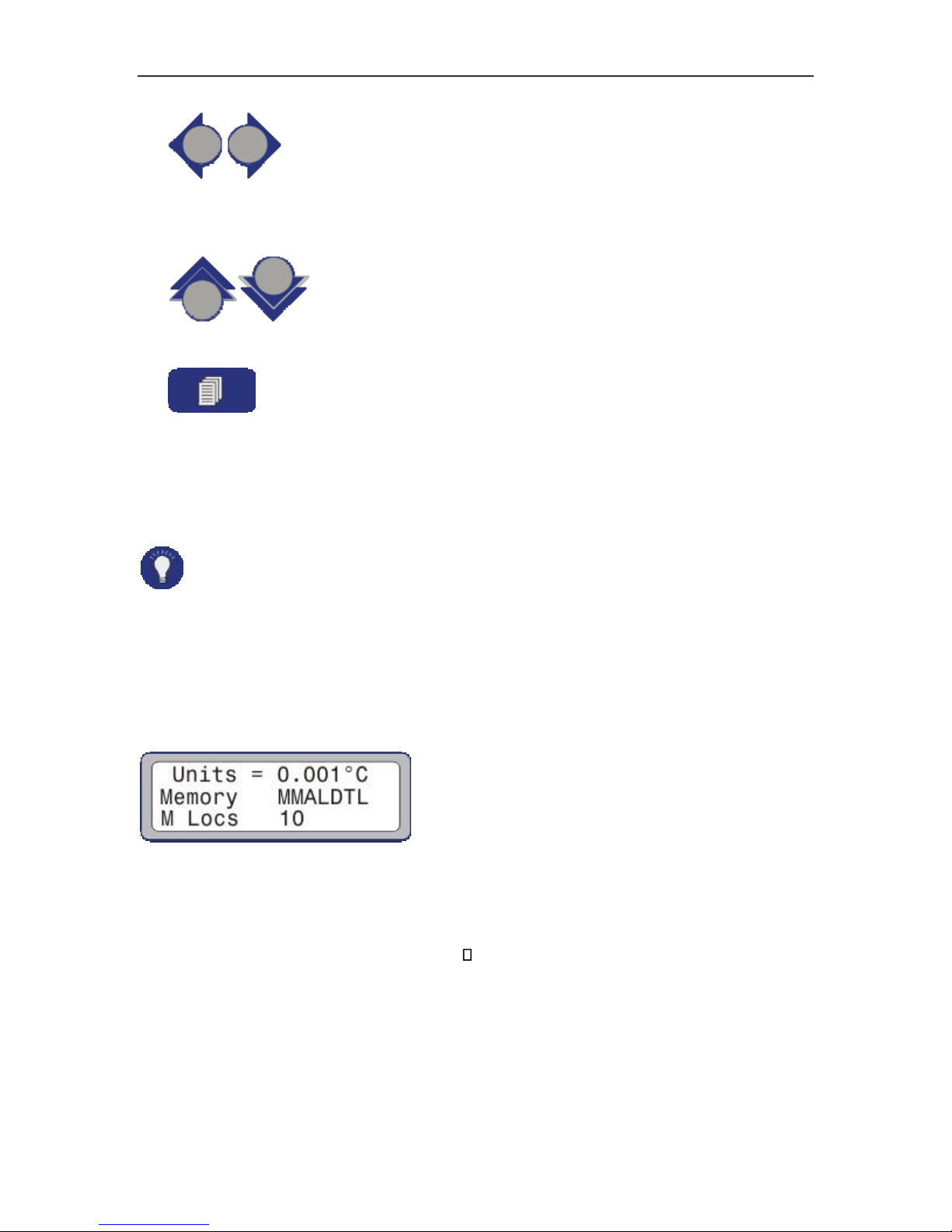
Setup Page #1
Units
The Units parameter specifies the measurement units. The options are: 0.01 °C, 0.001 °C,
0.01 °F, 0.001 °F, 0.01 K, 0.001 K, and . Temperatures are displayed with either two or
three digits of resolution. Resistance is displayed with three digits of resolution.
Memory
Page 3of 18 Jun10
Page 8

The Memory parameter specifies which Memory Data Items are displayable on the bottom of
the Data Page. There are seven possible Memory Data Items: Maximum, Minimum, Average,
Last, Date, Time, and Label. To specify whether a Memory Data Item is enabled or not,
toggle the associated character in the parameter string: MMALDTL. If the character is
displayed, the associated Memory Data Item is enabled. If ‘-‘ is displayed, the associated
Memory Data Item is disabled. For example, if MMA---- is displayed, Maximum, Minimum,
and Average will be the only Memory Data Items displayable on the bottom of the Data
Page.
.
Memory Locations
The M Locs parameter specifies the number of Memory Locations available for memory
storage. M Locs can be set between 1 and 100.
Note: The only purpose of the Memory and M Locs parameters is to reduce the amount
of information to scroll through when viewing Memory data on the Data Page.
Revision Page
To display the revision page, press the Right arrow key when Units is the highlighted
parameter.
To return to Setup Page #1, press the Left arrow key.
Setup Page #2
Page 4 of 18 Aug 08
Page 9

Model 310
The probe selection page is only displayed if the Model 310 has been enabled for the multiple
probe option.
Prb
The Prb parameter allows for selection of one of four programmed sets of coefficients.
S/N
S/N specifies the serial number for the selected sensor. The S/N parameter cannot be edited
on the probe selection page. It can only be edited in the sensor setup and calibration section
after entering the Unlock Code.
Mdl
Mdl specifies the model for the selected sensor. The Mdl parameter cannot be edited on the
probe selection page. It can only be edited in the sensor setup and calibration section after
entering the Unlock Code.
Setup Page #3
The spot offset page is not displayed if the Units parameter is set to .
SpotOff
The SpotOff parameter specifies the single point or “spot” calibration value. The difference
between the temperature measured by the Model 310 and a known calibration temperature is
entered as the spot offset value. Once entered, that value is then added to the measured
temperature to correct for the temperature difference. This provides excellent accuracy for a
narrow temperature range (± 5 °C) around the calibration point.
Page 5of 18 Jun10
Page 10

Setup Page #4
Contrast
The Contrast parameter allows for adjustment of the contrast of the LCD display.
Backlight Level
The Bklt Lvl parameter allows for adjustment of the intensity of the backlight on the LCD
display.
Backlight Time
The Bklt Time parameter specifies the amount of time (in minutes) the backlight on the LCD
display will automatically shut off after the backlight has been turned on.
Setup Page #5
Time
The Time parameter allows for entry of the current time of day in 24 hour format.
Date
The Date parameter allows for entry of the current date (mm-dd-yy).
Unlock
Enter the Unlock Code and press the “single” Down arrow key
Page 6 of 18 Aug 08
Page 11

Model 310
to display the sensor setup and calibration pages.
Note: The universal Unlock Code is 310000.
Setup Page #6
A
Specifies coefficient A for the connected sensor.
B
Specifies coefficient B for the connected sensor.
C
Specifies coefficient C for the connected sensor.
Setup Page #7
LeadRes
The LeadRes parameter specifies the lead resistance for the connected sensor. This value is
subtracted from the measured resistance before a resistance value is displayed or before a
temperature value is calculated and displayed.
Page 7of 18 Jun10
Page 12

Setup Page #8
Serial Number
The S/N parameter specifies the serial number for the connected sensor.
Mdl
The Mdl parameter specifies the model for the connected sensor.
Prb
The Prb parameter is only displayed if the Model 310 has been enabled for the multiple probe
option. The multiple probe option allows for storage of four sets of coefficients, lead
resistance, serial number, and model. The Prb parameter specifies the number (1 – 4) of the
active sensor.
Setup Page #9
Code
Specifies the Unlock Code needed on Setup Page #5 to access the sensor setup and
calibration pages.
Do Cal
When the Do Cal parameter is selected, press the Right arrow key to display The Model 310
Calibration Page #1.
Page 8 of 18 Aug 08
Page 13

Model 310
CalDue
Indicates the date the next calibration is due. This is automatically set at the completion of a
calibration.
Page 9of 18 Jun10
Page 14

Section 3
Data Page
Section 2 Model 310 Calibration
The Model 310 is calibrated at the factory before shipment. It is recommended that it be
recalibrated every year.
Calibration Points #0 and #1
The current calibration point and suggested calibration value (0 ohms for cal point #0 or 1500
ohms for cal point #1) are displayed. The actual calibration resistance value should be within 1 or
2 percent of the suggested value and known to within 0.0010% (10 ppm).
To calibrate, connect the calibration resistor, enter the actual resistance value, highlight Ok, and
press the Right arrow key to calibrate at each point. While the Model 310 is calibrating at each
point, “Pls Wait……..” is displayed.
The Data Page is displayed each time the Model 310 is powered or when the Setup key is pressed
from any Setup page.
Measurement Data
The continuously updated measurement value and units are displayed in large font at the top of
the screen. Temperatures are displayed with two digits of resolution. Resistance is displayed with
three digits of resolution.
Page 10 of 18 Aug 08
Page 15

Model 310
Condition
Display
No Sensor Attached
OPEN
< 100 Ω Measured
Resistance or OVER for temperature
> 9640 Ω Measured
OVER
If an over range condition has occurred, one of the following messages will be displayed in place
of the measurement value:
Notes: Temperature calculation errors are typically due to invalid coefficients.
Upon power up or when returning from the Setup level, “-------“ is temporarily
displayed until the first measurement has been completed.
When battery power gets low, the units display will alternate with a low battery symbol. When
the low battery symbol first appears, there will be approximately 20 minutes of
battery life left.
Memory Data Items are displayed in small font at the bottom of the screen. A label indicating the
currently displayed Memory Data Item is displayed first and is followed by a number from 0 to
99 indicating the currently selected Memory Location. The value of the Memory Data Item and
any applicable units are displayed to the right of the colon.
Data Page Operation
• To clear existing data and start collecting new data for the selected Memory Location, press
the “double” Down arrow key.
• To stop collecting data for the selected Memory Location, press the “double” Up arrow key.
• To change the currently displayed Memory Data Item, press either the Left or Right arrow
key.
Page 11of 18 Jun10
Page 16

Section 4
Remote Operation
Note: Only Memory Data Items selected as displayable by the Memory parameter are
available for display.
• To change the selected Memory Location, press either the “single” Up or “single” Down
arrow key.
Notes: The number of displayable Memory Locations is restricted by the M Locs
parameter.
When the selected Memory Location is changed, data will automatically stop being collected
for the previously selected location.
Serial communication with the Model 310 is performed via the DB9 connector on the top of the
unit. The Model 310 can be remotely operated from a host PC. Using PC generated serial
commands, it is possible to: 1. Query all the displayed real-time and saved data, 2. Query and
configure all setup parameters, and 3. Perform all front panel memory operations.
The Model 310 will attempt to process an incoming serial command each time it receives an
ASCII carriage return. When it finishes processing the command, it will send a response
indicating if the command was properly executed.
Command Process Responses:
0 Ok
1 Invalid Command
2 Invalid Memory Location
3 Invalid Value
The response will contain the Command Process Response followed by an ASCII carriage return
and an ASCII line feed.
<command process response><cr><lf>.
If the received command is a Query command, the Model 310 will send the Command Process
Response followed by <cr><lf> , the requested information, and another <cr><lf>.
<command process response><cr><lf><information><cr><lf>.
Page 12 of 18 Aug 08
Page 17

Model 310
1.1
Real-time Measurement Data
1.2
Maximum
1.3
Minimum
1.4
Average
1.5
Last
1.6
Units
1.7
Date
1.8
Time
1.9
Label (Set or Query)
2.1
Model Number (Query only)
The command structure consists of nodes that group related functionality. Each node is separated
by a decimal point.
When setting a value, the command must be followed by a space, the value, and then the ASCII
carriage return. When querying a value, the command must be followed by a space, a question
mark, and then the ASCII carriage return.
The RS232 commands are not programmable and are fixed at the following command structure.
Baud rate 9600, 8 bits , 1 stop , no parity
1 - Data Commands
Data commands are query only. Therefore, the space and question mark sequence are optional.
Real-time Measurement Data
Memory Data
The commands to access memory data are essentially the same for each memory location (0
to 99). To specify a data command for a memory location, append .x (where x is the number
of the memory location) to the end of the command. For example, the command to query
Memory Location 0 Maximum is 1.2.0 and the command to query Memory Location 57
Maximum is 1.2.57.
Note: If no location is specified, it is assumed to be location 0.
2 - Setup Commands
Page 13of 18 Jun10
Page 18

2.2
Software Revision (Query only)
2.3
Revision Date (Query only)
2.4
Units
0 1
2
3
4
5
6
0.01 ºC
0.001 ºC
0.01 ºF
0.001 ºF
0.01 K
0.001 K
Ω
2.5.1
Display Memory Maximum
0
1
No
Yes
2.5.2
Display Memory Minimum
0
1
No
Yes
2.5.3
Display Memory Average
0
1
No
Yes
2.5.4
Display Memory Last
0
1
No
Yes
2.5.5
Display Memory Date
0
1
No
Yes
2.5.6
Display Memory Time
0
1
No
Yes
2.5.7
Display Memory Label
0
1
No
Yes
2.6
Memory Locations (1 – 100)
2.7
Contrast (0 – 255)
2.8
Backlight Level (0 – 255)
2.9
Backlight Time (0 – 60)
2.10
Time (hh:mm:ss)
2.11
Date (mm-dd-yy)
2.12
Unlock Code (xxxxxxx)
4.1
Coefficient A
4.2
Coefficient B
4 – Thermistor Sensor Commands
Page 14 of 18 Aug 08
Page 19

Model 310
4.3
Coefficient C
4.4
Lead Resistance
4.5
Spot Offset
4.6
Serial Number
4.8
Model Number
5.1
Dump Memory
5.2
Clear All Memory
5.3
Set or Query Active Memory Location
5.4
Clear and Start Collecting Memory for Active Location
5.5
Stop Collecting Memory for Active Location
5 – Action Commands
All Action Commands with the exception of 5.3 are “trigger” only and cannot be queried. The
<cr> must follow the command with no other characters in between.
Section 5 Specifications
Instrument Range -5 to 105º C 23 to 221º F ITS-90 Coefficients
Instrument Uncertainty ±0.010º C -5 to 60ºC ±0.015ºC 60 to 105ºC ( 18 to 28º C )
Calibration Check 1 Year interval Resolution
0.01 or 0.001 ºC or ºF or K selectable
Excitation Current Nominal 250 ua
Sensor Type 2252 ohm @ 25ºC YSI 400 Series or equivalent
Sensor Coefficients Steinhart-Hart thermistor polynomial A,B & C
Operating Ambient 5º to 45º C
Humidity Less than 80% non-condensing
Warm Up Time Within specifications upon turn on, optimum after 15 minutes Temperature
Coefficient ± 5 ppm per Degree C from ambient
Display LCD with back light
Weight About 1 lb or 0.5 kg by itself
Page 15of 18 Jun10
Page 20

Power Battery operation up to 7 hours Use 4 NiMH batteries Warning!!Note Do Not Use
Carbon batteries in this unit as it could possibly damage the power supply
Do not charge batteries more than 48 hours. Over charging can cause batteries to weaken.
Charger Adapter 115 VAC input 6 VDC @ 300 ma output
Page 16 of 18 Aug 08
Page 21

Model 310
Section 6 Features
Timed backlight display with contrast adjustment
Multifunctional stand with lanyard hook and wall hanging slide
Thermal offset correction
RS232 port standard
Password protection capability
5 Pin DIN connector as standard thermistor connection
Easy 2 step resistance calibration
User friendly programming
Battery symbol to alert operator that a charge is needed
Page 17of 18 Jun10
Page 22

Section 7Select and Use Feature
The select and use feature is for the user that wants to use multiple thermistor sensors on his
Model
310 Hand Held unit. It is set up to be able to select 4 different thermistor sensors
Unless the user requests this feature the standard one input thermistor sensor will be furnished
when the 310 is initially shipped.
The select and use feature can be initiated by the user using the RS232 port The
commands are as follows.
3.10 1 (3.10space1) activates the select and use feature for 4 thermistor sensors
3.10 0 (3.10space0) returns the Model 310 to one input only
Once the select and use feature is activated then coefficients for the different thermistor sensors
must be programmed into the Model 310.
The model number and serial number must also be programmed into the memory thus identifying
that particular thermistor sensor with its particular coefficients.
When the Model 310 is powered up it will display the probe number and the serial that has been
selected. The user can change the probe (thermistor) at any time, by going into the menu and
making the proper selection.
Page 18 of 18 Aug 08
Page 23

Model 310
Page 19of 18 Jun10
 Loading...