


The subject of this document is the exclusive property of ITW Test and Measurement It alia S.r.l. - INSTRON CEAST Division. This
document or any part thereof must not be reproduced in any form, nor information contained therein disclosed to third parties nor
methods, procedures or test described therein performed, without the written permision of ITW T est and Measurement Italia S.r .l.
- INSTRON CEAST Division.
CEAST 9300 Series
Droptower Impact Systems
CEAST 9340
INSTRUCTIONS for USE
and MAINTENANCE
7510.000MN1r
ed. 1 rev. 1

Page 2 - CEAST 9340 - Instructions for Use and Maintenance 7510.000MN1r ed. 1 rev . 1
CONTENTS
LEGEND ...................................................................................................................................... 7
1. GENERAL INFORMA TION...................................................................................................... 8
1.1 EQUIPMENT DESCRIPTION .............................................................................................................11
1.1.1 INTRODUCTION ................................................................................................................................................ 11
1.1.2 MODULARITY .................................................................................................................................................... 11
1.1.3 DIFFERENCE BETWEEN INSTRUMENTS....................................................................................................... 11
1.1.4 MAIN PARTS OF INSTRUMENT ....................................................................................................................... 11
1.1.5 OPTIONS ........................................................................................................................................................... 13
1.2 TECHNICAL CHARACTERISTICS .................................................................................................... 14
1.2.1 LAYOUT .............................................................................................................................................................. 16
1.3 SAFETY ............................................................................................................................................. 17
2. CONDITIONS OF USE .......................................................................................................... 18
2.1 AUTHORIZED PERSONNEL ............................................................................................................. 18
2.2 NORMAL USE CONDITIONS ............................................................................................................ 19
2.3 ABNORMAL SITUATIONS................................................................................................................. 20
3. OPERATOR WORK STATION .............................................................................................. 21
2.4 SHIELDS............................................................................................................................................ 21
2.5 RESIDUAL RISKS.............................................................................................................................. 21
4. TRANSPORT AND MOVEMENT .......................................................................................... 22
4.1 LIFTING AND HANDLING ................................................................................................................ 22
4.1.1 MOVEMENT IN PACKAGING ............................................................................................................................ 22
4.1.2 MOVEMENT OF THE INSTRUMENT ................................................................................................................ 22
4.1.3 WEIGHT OF THE MAIN PARTS........................................................................................................................ 23
4.2 CHECK FOR POSSIBLE DAMAGE...................................................................................................23
4.3 STORAGE.......................................................................................................................................... 23
5. MOUNTING AND DISMANTLING.......................................................................................... 24
5.1 DISMANTLING THE PACKAGING CASE............................................................................................................. 24
6. INST ALLA TION...................................................................................................................... 25
6.1 SPACE AND ENVIRONMENT REQUIREMENTS ............................................................................. 25
6.1.1 SPACE................................................................................................................................................................ 25
6.1.2 ENVIRONMENT ................................................................................................................................................. 25
6.1.3 SERVICES .......................................................................................................................................................... 25
6.2 POSITIONING ................................................................................................................................... 26
6.2.1 SURFACE LOAD IN STATIC CONDITION ........................................................................................................ 26
6.2.2 LOAD ON SLAB ................................................................................................................................................. 27
6.2.3 INSTALLATION PROCEDURE .......................................................................................................................... 28
6.3 LEVELLING........................................................................................................................................ 32
6.4 STABILITY ......................................................................................................................................... 33
6.5 CLEANING......................................................................................................................................... 33
6.6 MATERIALS AND PRODUCTS ......................................................................................................... 33
7. START-UP ............................................................................................................................. 34
7.1 INSTRUMENT, CEAST DAS 8000 JUNIOR/CEAST 16000 AND PC CONNECTION....................... 34
7.2 ELECTRICAL SERVICE CONNECTION ........................................................................................... 34

CEAST 9340 - Instructions for Use and Maintenance 7510.000MN1r ed. 1 rev. 1 - Page 3
7.3 PNEUMATIC SERVICE CONNECTION ............................................................................................ 35
7.4 CRYOGENIC SERVICE CONNECTION ............................................................................................ 36
8. USE........................................................................................................................................ 38
8.1 SAFETY STANDARDS ...................................................................................................................... 38
8.2 COMPONENT IDENTIFICATION ...................................................................................................... 39
8.2.1 SAFETIES AND THEIR LOCATIONS ................................................................................................................ 41
8.3 COMMANDS...................................................................................................................................... 43
8.4 OPERATIONS.................................................................................................................................... 44
8.4.1 KEY FUNCTIONS ............................................................................................................................................... 44
8.4.2 PROGRAM ......................................................................................................................................................... 45
8.5 PROGRAM START - UP.................................................................................................................... 47
8.5.1 NAVIGATION THROUGH THE PROGRAM MENUS ........................................................................................ 48
8.5.2 MAIN MENU ....................................................................................................................................................... 50
8.5.3 SET TEMPERATURE ......................................................................................................................................... 51
8.5.4 LOAD PARAMETERS ........................................................................................................................................ 51
8.5.5 MODIFY PARAMETERS .................................................................................................................................... 52
8.5.6 SAVE PARAMETERS......................................................................................................................................... 56
8.5.7 RESULTS ........................................................................................................................................................... 56
8.5.8 UTILITY .............................................................................................................................................................. 57
8.5.9 INPUT PASSWORD ........................................................................................................................................... 58
8.5.10 CYCLE COUNTER ........................................................................................................................................... 59
8.5.11 FW VERSION ................................................................................................................................................... 59
8.5.12 MODIFY PASSWORD ...................................................................................................................................... 60
8.5.13 CLOCK ............................................................................................................................................................. 60
8.5.14 LANGUAGE ...................................................................................................................................................... 61
8.5.15 SERVICE .......................................................................................................................................................... 61
8.5.16 SHUTTER MOVING ......................................................................................................................................... 62
8.5.17 STRIKER RELEASE ........................................................................................................................................ 62
8.5.18 MOVE TO HEIGHT .......................................................................................................................................... 63
8.5.19 VISUALIZE SENSORS ..................................................................................................................................... 63
8.5.20 VISUALIZE I/O ................................................................................................................................................. 64
8.5.21 EMERGENCIES SYNOPTIC ............................................................................................................................ 64
8.5.22 ERROR CODES IN THE PROGRAM .............................................................................................................. 64
8.6 PREPARING THE INSTRUMENT FOR TESTING ............................................................................ 65
8.6.1 REPLACEMENT OF THE STANDS ................................................................................................................... 65
8.6.2 REPLACEMENT OF THE SPECIMEN FIXTURES............................................................................................ 66
8.6.3 REPLACEMENT OF THE STRIKER HOLDER.................................................................................................. 74
8.6.4 REPLACEMENT OF THE WEIGHTS ................................................................................................................ 76
8.6.5 REPLACEMENT OF STRIKER .......................................................................................................................... 78
8.6.6 REPLACEMENT OF THE STRIKER EXTENSION............................................................................................ 81
8.6.7 REPLACEMENT OF THE STRIKER’S HEADS (interchangeable head type) ................................................... 82
8.7 PREPARING THE INSTRUMENT FOR TENSILE-IMPACT TEST ONLY.......................................... 86
8.7.1 PROGRAM SETTING ........................................................................................................................................ 86
8.7.2 REPLACEMENT OF THE FIXED HEIGHT VICE SUPPORT STAND ............................................................... 88
8.7.3 REPLACEMENT OF THE PIEZOELECTRIC FORCE SENSOR ....................................................................... 90
8.7.4 REPLACEMENT OF THE INSTRUMENTED VICE FOR TENSILE-IMPACT.................................................... 92
8.7.5 REPLACEMENT OF THE TENSILE-IMPACT SPECIMEN ................................................................................95
8.7.6 REPLACEMENT OF STRIKER FOR TENSILE-IMPACT TESTS ...................................................................... 97
8.8 SUPPORT STANDS CODES 7520.350 AND 7520.351 FOR PLATES OF FIBER REINFORCED
POLYMERS ........................................................................................................................................ 98
8.8.1 INTRODUCTION ................................................................................................................................................ 98
8.8.2 COMPONENTS IDENTIFICATION .................................................................................................................... 98

Page 4 - CEAST 9340 - Instructions for Use and Maintenance 7510.000MN1r ed. 1 rev . 1
8.8.3 DISASSEMBLY AND ASSEMBLY OF THE SUPPORT STANDS ...................................................................... 99
8.9 SPECIAL-PURPOSE TOOLING FOR IMPACT TESTS ON PIPES ................................................ 100
8.9.1 INTRODUCTION .............................................................................................................................................. 100
8.9.2 SUPPORTS ...................................................................................................................................................... 100
8.9.3 SPECIAL HEADS FOR STRIKER.................................................................................................................... 102
8.10 CARRY OUT TEST........................................................................................................................ 103
8.10.1 OPERATING SEQUENCE OF AN INSTRUMENTED TEST ......................................................................... 103
8.11 SCREENS SHOWN DURING TEST.............................................................................................. 104
8.11.1 TEST START .................................................................................................................................................. 104
8.11.2 TEST IN PROGRESS..................................................................................................................................... 104
8.11.3 TEST END ...................................................................................................................................................... 105
9. MAINTENANCE ................................................................................................................... 106
9.1 SAFETY STANDARDS, GENERAL PROCEDURE ......................................................................... 106
9.2 FUSES REPLACEMENT ................................................................................................................. 107
9.3 CLEANING AND DRYING METHODS ............................................................................................ 109
9.4 PROCEDURE FOR LOADING FIRMWARE UPDATES...................................................................110
9.4.1 CONNECTION ................................................................................................................................................. 110
9.4.2 PREPARATION OF THE LOADING PROGRAM ............................................................................................. 110
9.4.3 LOADING ......................................................................................................................................................... 113
9.4.3.1 LOADER UPGRADE ..................................................................................................................................... 114
9.4.3.2 FIRMWARE UPGRADE ................................................................................................................................ 114
9.4.4 DISCONNECTION ........................................................................................................................................... 115
9.4.5 INSTRUMENT FIRMWARE CHECK ................................................................................................................ 115
9.5 REPLACEMENT OF THE IMPACT ROLLERS.................................................................................116
9.6 GREASING THE STRIKER RELEASING MECHANISM..................................................................117
9.7 LUBRICATING THE GEARING CHAIN ............................................................................................118
9.8 VERIFYING THE GEARING CHAIN TIGHTENING .........................................................................119
10. SPARE PARTS .................................................................................................................. 120
10.1 LIST OF RECOMMENDED SPARE PARTS................................................................................. 120
10.1.1 CEAST 9340 7515.000 AND 7516.000.......................................................................................................... 120
10.2 LIST OF SPARE PARTS FOR TECHNICAL ASSISTANCE........................................................... 121
10.2.1 CEAST 9340 CODE 7515.000 AND 7516.000 .............................................................................................. 121
10.2.2 ENVIRONMENTAL CHAMBER 7510.011 ...................................................................................................... 124
10.2.3 STRIKER ANTIREBOUND SYSTEM CODE 7510.002 ................................................................................. 125
11. TRAINING .......................................................................................................................... 126
11.1 GENERAL INFORMATION ............................................................................................................ 126
12. WIRING DIAGRAMS.......................................................................................................... 127
13. PNEUMATIC DIAGRAMS.................................................................................................. 148
APPENDIX A - CEAST 9340 PART LIST................................................................................ 151
APPENDIX B - TOOLING........................................................................................................ 154
APPENDIX C - TOOLING FOR TENSILE IMPACT TEST ONLY ........................................... 160
APPENDIX D - STRIKERS TECHNICAL FEATURES ............................................................ 161
APPENDIX E - INPUT LIST..................................................................................................... 165
APPENDIX F - OUTPUT LIST................................................................................................. 167

CEAST 9340 - Instructions for Use and Maintenance 7510.000MN1r ed. 1 rev. 1 - Page 5
APPENDIX G - ERROR CODES LIST .................................................................................... 1 69
APPENDIX H - STRIKER ANTIREBOUND SYSTEM ............................................................. 178

Page 6 - CEAST 9340 - Instructions for Use and Maintenance 7510.000MN1r ed. 1 rev . 1
PRINT DATE: MARCH 02, 2010
REVISION TOPIC:
REVISION: 1
EDITION: 1
- Changed the legal name of the firm from "Instron" to "ITW Test and Instrument Italia S.r.l. - INSTRON
CEAST Division" where necessary.
- Appendix G: changed “Instron Service” with “Authorized Service” in the tables of Error Codes Lists,
pages 168, 172, 173 and 174.

CEAST 9340 - Instructions for Use and Maintenance 7510.000MN1r ed. 1 rev. 1 - Page 7
LEGEND
X
Perform the operations indicated by this symbol.
Additional information, observations, explanations and recommendations.
Potential danger of extremely risky situation for life or health .
Beware of potential danger to the operator and/or risk of equipment damage.
These symbols are used to focus the attention of the operator on the most important or critical
points provided in this document.

Page 8 - CEAST 9340 - Instructions for Use and Maintenance 7510.000MN1r ed. 1 rev . 1
1. GENERAL INFORMATION
Description: CEAST 9340
Manufacturer: ITW Test and Instrument Italia S.r.l. - INSTRON CEAST
Division
Type: Droptower Impact System
Code: the code number of the instrument can be found on the ID
plate (on the rear panel)
Registration: the registration number of the equipment can be found on
the ID plate (on the rear panel)
Electric Service: 230 V / 50 Hz - single phase
Identification
Conformity
Field of
application
Authorized
Service
Centers
Contact your nearest Instron CEAST Division Sales and Service office or
contact your local distributor: a list of Instron CEAST Division offices is
available on our websites: www.ceast.com and www.instron.com.
Markings
The plate with the CE marking and the identification information is located
on the rear panel of the instrument (see the figure below).
Indication
of danger
due to
electric
shock
On the instrument there are plates with various danger signals. These
plates act to advise the user and the maintenance personnel of the type of
danger that exists in the local area next to the plate.
Physical contact with parts of the equipment that have electrical current
can cause immediate death or permanent wounds. Safety protection, fixed
panels, flaps or doors that have this signal can be removed or opened only
and exclusively by “Maintenance Personnel, qualified or trained” after disconnecting the instrument from the electrical service and removing the
plug from the electrical socket.
The equipment is used for instrumented and not instrumented impact tests
on plates, films specimens and tridimensional parts of thermoplastic materials.
See the “Conformity Declaration” attached

CEAST 9340 - Instructions for Use and Maintenance 7510.000MN1r ed. 1 rev. 1 - Page 9
Indication
of danger
due to low
temperature
WARNING !
The liquid nitrogen tank must be handled with extreme care.
Nitrogen in the liquid state has a temperature of -196 °C and it is therefore very
dangerous.
The user must not stand in front of the discharge valves of tank when regulat-
ing the pressure or touch with his bare hands the top central part of the tank as
there could be a risk of burns.
During the tank filling and handling operations
it is compulsory to wear ther-
mally insulated gloves and other protective clothes.
The room in which the nitrogen is used must be well ventilated to avoid envi-
ronment saturation problems (lowering of the oxygen percentage) with a risk of
suffocation.
The liquid nitrogen tank (option) is supplied on request and it must be used
only for low temperature tests with the Resilvis instruments code 7526.000.
Emissions
Acoustic emission level:
without Additional Energy System < 70 dB (A)
with Additional Energy System < 110 dB (A) (for less than 1 second)

Page 10 - CEAST 9340 - Instructions for Use and Maintenance 7510.000MN1r ed. 1 rev . 1
HAZARD IDENTIFICATION
Nitrogen is colourless, odourless, non-flammable, non-irritating and non-toxic gas.
It is classified as a Simple Asphyxiant under OSHA regulations.
Can cause suffocation by reducing oxygen available for breathing.
Breathing very high concentration of vapour can cause dizziness, shortness of
breath, unconsciousness, or even death.
There are no currently Occupational Exposure Limit Values for this component
but it is recommended to maintain oxygen levels at or above 19,5%.
Use only in a well ventilated place.
Local exhaust system of 1200 m
3
/hour is recommended
to prevent high nitrogen concentration when use the CEAST 9340
equipped with the environmental chamber.
Avoid direct inhalation of undiluted gas.

CEAST 9340 - Instructions for Use and Maintenance 7510.000MN1r ed. 1 rev. 1 - Page 11
1.1 EQUIPMENT DESCRIPTION
CEAST 9340 is a droptower impact system used for instrumented and not instrumented
test on plates, films specimens and tridimensional parts, according to the requirements
prescribed in the standards: ISO 179-2, ISO 180, ISO 3127, ISO 6603-1, ISO 6603-2,
ISO 7765-2, ASTM D 256, ASTM D 2444, ASTM D 3763, ASTM D 5628, ASTM D 6110,
ASTM D 7136, ASTM D 7192, ASTM E 23, PR-EN 6038, AIRBUS AITM 1.0010 and
other equivalent standards.
1.1.3 DIFFERENCE BETWEEN INSTRUMENTS
••
••
• CEAST 9340 code 7515.000: it is equipped with a standard chamber for tests at
ambient temperature;
••
••
• CEAST 9340 code 7516.000: it is equipped with an environmental chamber for speci-
mens conditioning at temperatures: - 50 °C to 100 °C.
The environmental chamber is cooled through the expansion of liquid nitrogen taken
from an external tank or from the laboratory's nitrogen line (N
2
) if available. The nitro-
gen flows inside the chamber through pipes endowed with capillary holes.
The chamber is heated by means of heating resistances.
The uniformity of the temperature is assured through an electric fan which recircu-
lates air and nitrogen inside the chamber.
The temperature sets by the operator is automatically controlled by a temperature
regulator. This device receives the signal from a temperature probe located inside
the chamber and, depending on whether the requirement is for cold or hot, it enable
a solenoid valve to open the nitrogen inlet or the electric heating resistance.
1.1.2 MODULARITY
1.1.1 INTRODUCTION
CEAST 9340 has been designed and manufactured with a concept of modularity. In fact
the instruments is pre-arranged for an easy and quick addition and connection of all
options at a later date.
1.1.4 MAIN PARTS OF INSTRUMENT
Instrument consists of the following parts:
••
••
• Turret: it is the upper part of the instrument, secured to the test chamber by screws.
Inside the turret is housed:
- Automatic striker recovery/releasing system: it is used to moves the striker at
the correct height and to release it for impact test on the specimen.
-Striker holder: it joints mechanically the striker to the recovery/releasing sys-
tem. Moreover it can contains one or more weights used to increase the impact
mass.
The striker holder can be of two different types: light (for masses 1 to 3.5 kg,
striker included) or standard (for masses: 3 to 37 kg, striker included).

Page 12 - CEAST 9340 - Instructions for Use and Maintenance 7510.000MN1r ed. 1 rev . 1
••
••
• Test chamber: see para. 1.1.3.
Both chambers (standard and environmental) can be equipped with different stands,
such as:
- Fixed Height Stand;
- Adjustable Height Stand;
Many other stands are available according to the Client needs.
- Automatic clamping device: it clamps the specimen on the support before the
striker impact.
••
••
• Control box: it is the box attached to the right side of turret and it is provided of the
following parts:
- Power ON: it is a push-button to energize the instrument;
- Emergency: it is used only when an emergency condition arises.
When this button is pressed it cuts off the electrical power to the instrument.
To re-energize the instrument, disengage the Emergency button (half a turn in
clockwise direction) and re-press the Power ON push-button.
- Alphanumeric keypad with LCD display: it is used to program and manage the
tests.
It allows to enter all the test parameters required to carry out the automatic
impact cycle and to recall the results on display at the cycle end.
The instrument memory is able to store up to 25 sets of test parameters.
-Striker: it is used to strike the specimen surface when the impact test is carried out.
Striker can be of two different types:
Non-instrumented: it is used for a simple statistical check of the material impact
strenght (visual check of the specimen: broken/not broken).
Instrumented: it provide full details of the impact event from initial contact to
final breaking of the specimen by recording the force/time curve of the entire
impact event through a data acquisition system connected to a PC.
Data acquisition system (option) at which the instrumented striker is connected
can be of two different types: CEAST DAS 8000 Junior or CEAST DAS 16000.
The number identifies the max. number of points acquired during the impact
event.
For further details about strikers see the Appendix B attached to this manual.
-Striker antirebound system (option): it stops the striker after impact to avoid its
rebound on the specimen. This system intervenes only in case of striker rebound.
-Residual energy absorbers: they are used to damp the striker residual energy
after impact and they are placed on the turret base at the left and right sides.
-Impact and rebound velocity optical detector: it is used to measure the velocity of the striker just
before the impact and to activate the striker antirebound
system in case of striker rebound.
It consists of a photocell fixed with a bracket to the turret structure and a flag
fixed to the striker holder. When the striker holder is released for test, the flag
pass through the photocell interrupting the light-ray two time consecutively.

CEAST 9340 - Instructions for Use and Maintenance 7510.000MN1r ed. 1 rev. 1 - Page 13
1.1.5 OPTIONS
Options code
Environmental chamber, temperature range: -50 to 100 (already included in the
instrument code 7516.000)
7510.011
Striker antirebound device
7510.002
Standard striker holder (3 to 37 kg) with combinable weights
7510.021
Light striker holder (1 to 3.5 kg) with combinable weights
7510.022
Set of additional weights for standard striker holder (no. 3 masses, 5 kg each)
7510.026
Fixed height stand for specimen support (single impact).
Max. specimen thickness 25 mm
7520.031
Adjustable height stand for specimen support (single impact).
Max. specimen thickness 195 mm
7520.035
Note: the table above summarises only the main options. Many other options are available such as: strikers, specimens supports, adapters, etc..

Page 14 - CEAST 9340 - Instructions for Use and Maintenance 7510.000MN1r ed. 1 rev . 1
1.2 TECHNICAL CHARACTERISTICS
Instr umen t Co de 7515.000 7516.000
Functional Characteristics
Drop height range [mm] 30 to 1100
Mass range [kg] light striker holder 1 to 3.5
standard striker holder 3 to 22
standard striker holder
and additional masses
3 to 37
Speed range [m/s] 0.77 to 4.64
Energy range [J] light striker holder 0.3 to 37
standard striker holder 0.89 to 237
standard striker holder
and additional masses
0.89 to 400
Test temperature [°C] ambient - 50 to 100, selectable
by increments of 1 °C
Temperature control - by Pt 100 sensor and
PID thermoregulator
Over temperature control - by safety thermostat
Heating system - by electric resistances
Cooling system - by liquid nitrogen
Average heating speed - 1 °C / minute
Average cooling speed - 4 °C / minute
Impact and rebound velocity measured by optical detector
Striker position measured by digital encoder
Specimen clamping on support by clamping device, pneumatically actuated

CEAST 9340 - Instructions for Use and Maintenance 7510.000MN1r ed. 1 rev. 1 - Page 15
Instrument Code 7515.000 7516.000
Technical Data
Electric Power Supply
Voltage [V] - Phases - Frequency [Hz] 230 - Single phase - 50/60
Total installed power [W] 600
3200
Fuses see attached wiring diagrams
Earth path in accordance with local regulations
Pneumatic Air Supply (compressed air)
Pressure at instrument inlet [bar] 10 max.
Working pressure [bar] 5
Liquid Nitrogen Supply
Pressure at instrument inlet [bar] - 7 max.
Working pressure [bar] - 1.2
Consumption at - 40 °C [kg/h] - 4
Consumption to cool from 23 to - 40 °C [kg] - 6
Overall Dimensions
Instrument (W x D x H) [mm] see 1.2.1 Layout drawing
Inner Dimensions
Test chamber (W x D x H) [mm] 490 x 450 x 565 370 x 300 x 495
Connection see 1.2.1 Layout drawing
Weight
Instrument [kg] 340 400
Paint
Grey RAL 7035 - Fuchsia RAL 4006

Page 16 - CEAST 9340 - Instructions for Use and Maintenance 7510.000MN1r ed. 1 rev . 1
1.2.1 LAYOUT

CEAST 9340 - Instructions for Use and Maintenance 7510.000MN1r ed. 1 rev. 1 - Page 17
1.3 SAFETY
••
••
• The instrument is supplied with fixed and movable shields.
The fixed ones (fastened with screws) are located to the sides and rear of the turret
and rear of the environmental chamber (option) to prevent anyone accessing the
interior.
The hinge-mounted movable shields (hinge-mounted) are provided with safety
microswitches and are located at the front of turret and test chamber and allow the
operator to access the work areas for routine operations. When these shields are
opened, the safety microswitches disable operation of movable parts and heating/
cooling systems.
••
••
• The instrument is controlled by keys located on the keypad of the control box or by
the PC.
••
••
• The instrument can only be used by trained, qualified and authorized personnel.
••
••
• The responsibility for the various activities, for the operation of the instrument, must
be clearly established as indicated in the following chapter and therefore respected.
••
••
• If the electric cable is damaged or cut, it must be replaced.
••
••
• For all of the work to be done regarding: installation, start-up, tooling, use, modifica-
tion conditions of use, and work instructions, the procedures indicated in this manual
must be followed.
••
••
• This manual must always be accessible, so that it can be consulted in case of doubts
about the correct conditions of use of the instrument.

Page 18 - CEAST 9340 - Instructions for Use and Maintenance 7510.000MN1r ed. 1 rev . 1
2. CONDITIONS OF USE
2.1 AUTHORIZED PERSONNEL
After receiving all necessary instructions contained within this manual, only the following professionals may work on this instrument:
OPERATOR
The Operator of the CEAST 9340 must have a specific qualification from a recognized
school for analogous apparatus, or under the guidance of expert personnel. The operator can perform only the operations indicated and specified in this manual, following the
instructions herein. The instrument should not be used by un-expert personnel.
MECHANIC
The Mechanic must have general experience on test equipment and specific experience with the CEAST 9340 or analogous instrument. The mechanic can perform only
the operations indicated and specified in this manual, following the instructions herein.
ELECTRICIAN
The Electrician must have general experience with switch boxes and electronic components and have specific experience on the CEAST 9340 control box or similar instruments. The electrician can perform only the operations indicated and specified in this
manual, following the instructions herein.
SAFETY MANAGER
The Safety Manager is responsible for the protection and prevention of corporate risks,
according to the indications of the International Standards. The Safety Manager must
ensure that all personnel who operate the instrument have received the instructions
contained in this manual for their position including installation and start-up.
MANUFACTURER
For all operations not expressly foreseen in this manual and assigned to one of the
above professional figures, it is necessary to contact ITW Test and Instrument Italia
S.r.l. - INSTRON CEAST Division. The aforementioned operations can only be performed by ITW T est and Instrument Italia S.r.l. - INSTRON CEAST Division, or under
authorization and according to the instructions provided by ITW Test and Instrument
Italia S.r.l. - INSTRON CEAST Division, by specialized personnel at the user’s location, who are qualified Mechanics or Electricians.

CEAST 9340 - Instructions for Use and Maintenance 7510.000MN1r ed. 1 rev. 1 - Page 19
The instrument, subject of this manual, must be used only and exclusively to carry out
impact tests on plates, films and tridimensional parts of thermoplastic materials.
All of the operations for preparation of the instrument for carry out tests, and those
performed at the end of the tests (e.g.: specimen replacement, chamber cleaning, etc.),
must be manually performed by the operator.
Maintenance and instrument regulation (e.g.: replace fuses, installation of additional
modules, etc.) must be performed by persons who are qualified mechanics or electricians (see the chapter on maintenance).
The instrument is sent to the customer in two separate parts: turret and test chamber;
the USER must provide for the positioning and assembling of these parts in the laboratory, and their connection to the electric/pneumatic facilities.
After 20,000 hours of work, and in any case not longer than 10 years, a complete overhaul of the apparatus by ITW Test and Instrument Italia S.r.l. - INSTRON CEAST Division is necessary in order to continue to use it safely. The cost of overhaul are the
responsibility of the CUSTOMER.
2.2 NORMAL USE CONDITIONS

Page 20 - CEAST 9340 - Instructions for Use and Maintenance 7510.000MN1r ed. 1 rev . 1
2.3 ABNORMAL SITUATIONS
ÖÖ
ÖÖ
Ö
ÖÖ
ÖÖ
Ö
ÖÖ
ÖÖ
Ö
ÖÖ
ÖÖ
Ö
ÖÖ
ÖÖ
Ö
ÖÖ
ÖÖ
Ö
ÖÖ
ÖÖ
Ö
ÖÖ
ÖÖ
Ö
ÖÖ
ÖÖ
Ö
ÖÖ
ÖÖ
Ö
ÖÖ
ÖÖ
Ö
It is absolutely necessary that the instrument be used in the conditions prescribed
in this instruction manual; no modifications to the instrument or its safeties are
permitted, nor is its use in abnormal conditions.
Below the USER is advised of a few of the recommendations to avoid abnormal
conditions of use; in any case any other condition of use that is not expressly
foreseen by this manual must be avoided.
Run the instrument only if it is installed in the prescribed position (vertical).
Avoid that people other than the operator can use the instrument while it is func-
tioning.
Do not put objects between the striker and the base plate of the turret and on the
specimen support when the instrument is running.
Do not touch the materials inside the environmental chamber during testing at
high or low temperature. Always wear thermally insulated gloves.
Do not operate the instrument if the protections are removed or not properly
fitted.
Do not remove or alter the position of the safety microswitches or the tempera-
ture sensors (with enviromental chamber only) installed on the instrument.
Do not climb on or get on top of the instrument.
Do not put material in the test chamber that differs from that prescribed (
use only
plates, films and tridimensional parts of thermoplastic materials).
Do not operate the instrument with the fixed shields dismantled or incorrectly
mounted.
Should the CUSTOMER install a tool or sp are p art on the instrument that has not
been supplied by ITW T est and Instrument Italia S.r .l. - INSTRON CEAST Division,
he must verify that the safety measures are maintained. Regardless, in this case
ITW T est and Instrument It alia S.r .l. - INSTRON CEAST Division does not assume
the responsibility for any eventual damages derived from the use of the aforementioned part.
The instrument must not be installed or operated in a
corrosive or explosive
environment.
Do not wash the instrument with water jets or flammable materials (e.g.: diesel
fuel, gasoline, solvents, etc.).
ÖÖ
ÖÖ
Ö

CEAST 9340 - Instructions for Use and Maintenance 7510.000MN1r ed. 1 rev. 1 - Page 21
2.4 SHIELDS
It is absolutely necessary that the
instrument operates with all of the
shields always closed. The fixed
shields must always be mounted
and permanently blocked.
2.5 RESIDUAL RISKS
The operators pay particular attention to the points indicated in
the figures.
Do not touch the materials
inside the environmental
chamber during tests at
hight/low temperature.
Use thermally insulated
gloves
DANGER OF BURNS
Do not put hands or objects where
indicated by the arrows
DANGER OF CRUSHING
Mobile shield
(doors)
Fixed
shields
Risk of fingers
crushing during
the weights
replacement
DANGER OF
CRUSHING
Risk of weights
falling during the
weights replace-
ment
DANGER OF
INJURY
Pneumatic cylinders of clamping plate
remain pressurized also in case of
power cut off avoiding the clamping
plate lowering
Operator at work station
The operator must always work in
such a manner to have easy access
to the commands, and at the same
time have complete visibility of the
instrument.
3. OPERATOR WORK STATION

Page 22 - CEAST 9340 - Instructions for Use and Maintenance 7510.000MN1r ed. 1 rev . 1
Transportation may be done with the instrument “visible” or enclosed in special packaging (e.g.: wooden crates).
T ransportation is normally performed by TRANSPOR TERS, who are the CUST OMER’S
responsibility.
The instrument is normally transported in a crate and packed in horizontal position.
During transport the crate, containing the instrument, must be firmly held down with
cables or straps in order to impede movement.
The means of transport and lifting must always be done according to the given indications
by trained personnel (e.g.: warehouse personnel, forklift workers, or crane workers).
4. TRANSPORT AND MOVEMENT
4.1 LIFTING AND HANDLING
4.1.2 MOVEMENT OF THE INSTRUMENT
X
The instrument is equipped with six eyebolts (four on the upper part of the turret and two
on the lower right side of the test chamber) that are used to lift it by ropes and a forklifts.
Leaves the pallet on the floor of the laboratory. Move and place the instrument in vertical position following the procedure described in chapter 6.2.3 Installation Procedure.
When the instrument is in vertical position, use always the four eyebolts (on the upper
part of the turret) to lift and move it in the laboratory.
During movement of the instrument, proceed slowly
4.1.1 MOVEMENT IN P ACKAGING
When the instrument is moved in crates, it
is necessary to use a forklift or pallet-mover .
The lifting points for the forks of the forklift
are indicated in the figure to the right.
The weight of the crate containing the instrument is approximately 550 kg. Lifting machinery must therefore be
able to lift these loads.
X

CEAST 9340 - Instructions for Use and Maintenance 7510.000MN1r ed. 1 rev. 1 - Page 23
4.2 CHECK FOR POSSIBLE DAMAGE
X
X
X
On reception of the goods, it is necessary to perform a visual inspection of the packaging and instrument in order to identify any damage sustained during transport and movement.
If the packaging is damaged, immediately send by fax to ITW Test and Instrument Italia
S.r.l. - INSTRON CEAST Division the details of the damage sustained; or, indicate the
damages directly on the transport document and send this via fax to ITW Test and
Instrument Italia S.r.l. - INSTRON CEAST Division.
If the instrument or accessories should be damaged or missing, it is imperative to not
continue with the installation, but to notify ITW Test and Instrument Italia S.r.l. - INSTRON
CEAST Division immediately via fax of the anomaly found, and to agree with the former
the action to be taken.
4.3 STORAGE
Should the instrument need to be stored until a later date, the environment must be the
same as that for work.
If there are any storage requirements that should require special packaging, they must
be requested from ITW Test and Instrument Italia S.r.l. - INSTRON CEAST Division.
4.1.3 WEIGHT OF THE MAIN PARTS
The table below indicates the approximate weight of the CEAST 9340 instruments and
they can help the warehouse personnel or forklift workers in the choise of the hoister or
forklift appropriate.
Instrument Weight [kg]
9340 code 7515.000
(with standard test chamber)
340
9340 code 7516.000
(with environmental test chamber)
400

Page 24 - CEAST 9340 - Instructions for Use and Maintenance 7510.000MN1r ed. 1 rev . 1
X
5. MOUNTING AND DISMANTLING
X
X
X
X
X
The instrument is handled completely assembled.
Therefore there are no assembly and/or disassembly operations to carry out before
handling.
Should the USER need to dismantle one or more parts for which the procedure is not
included in this manual, it is imperative that ITW T est and Instrument Italia S.r.l. - INSTRON
CEAST Division be contacted for authorization and the procedure.
Every operation of mounting/dismantling done by the USER, not foreseen in this manual
nor authorized by ITW Test and Instrument Italia S.r.l. - INSTRON CEAST Division, will
be considered altering and will result in the compromise of the safety functions and
guarantee of the instrument.
Should the instrument be transported packaged in a
crate, it is necessary to:
a) Transport the crate to the place of installation. The
floor must be perfectly flat and capable of support a
weight of 1000 kg/m
2
(see para. 6.2.2).
Note: put on protective glasses before removing
straps.
b) Cut the straps.
c) Remove the screws or nails of the lid and remove it.
d) Remove the screws or nails of the walls and remove
them.
e) Remove the packing material.
f) Unscrew the screws and nuts and remove the brack-
ets that fastening the instrument to the pallet (see
figures on para. 6.2.3).
g) Continue with the handling of the instrument accord-
ing to the instructions in chapter 4.1.2.
A
X
B
C
Crate overall dimensions [mm]
and gross weight [kg]
A = 130;
B = 277;
C = 87;
Weight = 550 kg approx.
Walls
Lid
Pallet
5.1 DISMANTLING THE P ACKAGING CASE

CEAST 9340 - Instructions for Use and Maintenance 7510.000MN1r ed. 1 rev. 1 - Page 25
6. INSTALLATION
6.1 SPACE AND ENVIRONMENT REQUIREMENTS
6.1.1 SP ACE
6.1.2 ENVIRONMENT
6.1.3 SERVICES
Installation of the instrument must be performed according to the instructions, by trained
qualified personnel, Mechanics or Electricians as specified according to the needs.
The instrument will work according to the technical parameters foreseen if it is correctly
placed, stably, in a laboratory on the floor that is able to hold the instrument weight.
Before installing the instrument, determine the correct place to position it. Remember
that it is necessary to consider the following requirements: space restraints, absence of
vibrations, temperature, humidity and atmosphere (not corrosive, not polluted, not ex-
plosive).
The spatial dimensions of the instrument are indicated in paragraph 1.2.1. Remember
to leave adequate space all around the instrument (about 1 meter) and on top of it
(about 1 meter) to allow the access of maintenance personnell.
The instrument must be installed in a controlled temperature and humidity laboratory. If
this is not possible, it should be located in a clean environment where the temperature
range is between 15°C and 35°C with relative humidity (RH%) ≤ 85 % (without conden-
sation).
The location determined for the installation of the instrument must have an electrical socket
according to the information on the ID plate of the instrument (see chapter 1) and a pneu-
matic air supply line (see paragraph 1.2) able to delivery compressed air with pressure 7 to
10 bar.

Page 26 - CEAST 9340 - Instructions for Use and Maintenance 7510.000MN1r ed. 1 rev . 1
6.2 POSITIONING
The instrument will function according to the technical parameters foreseen if it is correctly positioned vertically on a planar surface.
Note: the calculation of the surface load of each foot is performed in the most conservative manner for an instrument with all options.
An instrument (with environmental chamber) weighs approximately 400 kg, when it is
equipped with a full set of additional weights (37 kg) and with a specimens support (20
kg), the total weight becomes 457 kg approx. (4483 N).
6.2.1 SURF ACE LOAD IN STATIC CONDITION
The surface on which the instrument is placed must be
able to hold a minimum weight
of 1.5 kg/cm2 (15 N/cm2) at the
location of each foot.
A
B
C
Standard foot (x 4)
View from the top
Front side
Suggestions: place the instrument on the ground floor of reinforced-concrete
and far from other instruments for vibration problem.
Weight of instrument equipped with thermostatic chamber, additional weights set and
fixed height stand [kg]
457
Distance between feet: A; B [cm] 69; 51
No. o f rest fe et 4
Diameter of each rest foot: C [cm] 10
Surface of one rest foot [square cm] 78.5
Weight exerted on one rest foot [kg] (considering uniform weight distribution) 115
Weight-to-Surface Ratio on one rest foot [kg/square cm] 1.5

CEAST 9340 - Instructions for Use and Maintenance 7510.000MN1r ed. 1 rev. 1 - Page 27
6.2.2 LOAD ON SLAB
The slab on which the instrument is placed must be able
to hold at least 1000 kg/m
2
(10000 N/m2)
LOAD ON SLAB IN STATIC CONDITION
(for storage)
The slab on which the instrument is placed must be able
to hold at least 2000 kg/m
2
(20000 N/m2)
LOAD ON SLAB IN DYNAMIC CONDITION
(load calculated for tests in the worse condition
using materials very tough)

Page 28 - CEAST 9340 - Instructions for Use and Maintenance 7510.000MN1r ed. 1 rev . 1
6.2.3 INST ALLATION PROCEDURE
X
Should the instrument be transported packaged in a crate, it is necessary to:
a) Transport the crate to the place of installation. The floor must be perfectly flat and
capable of support a weight of 1000 kg/m
2
(see para. 6.2.2).
b) Dismantling the packaging case following the instructions of para. 5.1.
c) Remove the screws (x 6) and brackets (x 6) fastening the instrument to the pallet
(Fig. 1 and detail).
Fig. 1
Bracket (x 6)
Screw (x 6)
X
X

CEAST 9340 - Instructions for Use and Maintenance 7510.000MN1r ed. 1 rev. 1 - Page 29
d) Reeve the ropes through the four eyebolts as shown (arrows) in the details of Fig. 2.
e) Place the ropes on the forks of two forklifts or bridge cranes.
Fig. 2
X
X

Page 30 - CEAST 9340 - Instructions for Use and Maintenance 7510.000MN1r ed. 1 rev . 1
f) Lift the instrument and remove the pallet below (Fig. 3).
g) Continue to lift the instrument to the (Fig. 4) driving it opportunely until it touches the
floor with two feets (take care do not damage the feets during this operation) and
then with all four feet (vertical position).
Fig. 3
Fig. 4
X
X

CEAST 9340 - Instructions for Use and Maintenance 7510.000MN1r ed. 1 rev. 1 - Page 31
Fig. 5
Fig. 6
h) Lower the forks of the forklifts and remove the ropes from the eyebolts (Fig. 5).
i) Remove the two eyebolts on the right side of the instrument.
j) Remove the two support brackets from the sides of the instrument (Fig. 6).
k) When the instrument is in vertical position, use always the four eyebolts (on the
upper part of the turret) to lift and move it in the laboratory.
X
X
X
X

Page 32 - CEAST 9340 - Instructions for Use and Maintenance 7510.000MN1r ed. 1 rev . 1
Spirit level
(longitudinal
position)
Crosshead
guide column
Spirit level
(transversal
position)
Fig. 1 Fig. 2
Notes:
- Figs. 1 and 2 show the spirit level placed against the guide column to visually inspect
the verticality of the instrument on the longitudinal and trasversal positions.
- Fig. 3 shows a forklift under the instrument base. It must be used to lift (only 2 or 3 cm)
the instrument before turn the feet for levelling. When the feet are adjusted, lower the
instrument and check again the level. If necessary, lift and lower the instrument and
adjust the feet height more times until the instrument is levelled.
- Fig. 3 detail A, shows the adjustable foot in normal position (exagonal lock nut tighten
against the instrument frame).
- Fig. 3 detail B, shows the adjustable foot in levelling position (exagonal lock nut tighten
against the foot exagonal nut).
a) Open the turret door.
b) Place the spirit level against a guide column (Fig 1). Visually inspect the verticality of
the instrument.
c) If it is not correct, turn the feet on instrument right side using the adjustable wrench.
d) Change the position of the spirit level (Fig 2). Visually inspect the verticality of the
instrument.
e) If it is not correct, turn the feet on instrument front using the adjustable wrench.
f) Repeat instructions from paragraph b) to f) included, up to reach the level required.
g) Once levelled, check that the four feet are in contact with the floor.
The instrument is provided for with four adjustable support feet (see figures) for levelling. To perform this operation, follow instructions in the paragraphs below:
X
X
X
X
X
X
X
6.3 LEVELLING

CEAST 9340 - Instructions for Use and Maintenance 7510.000MN1r ed. 1 rev. 1 - Page 33
6.4 STABILITY
The instrument is stable if placed with all four feet touching a planar surface.
6.5 CLEANING
6.6
MATERIALS AND PRODUCTS
The instrument does not require cleaning with protective substances (e.g.: grease or oil
on the surfaces). In any case, should it become dirty during installation, clean the sur-
faces with a soft cloth and non-corrosive and not dangerous detergent that will not
damage the painted surfaces. In any case all safety indications provided by the manu-
facturer of the cleaning solutions must be followed.
The instrument is primarialy constructed from: iron, steel, aluminium, copper, light alloys
and thermal insulation (for environmental chamber only) not containing asbestos.
External parts of the environmental chamber are painted. The maximum external tem-
perature that can be reached by these parts is approximately 40°C, a temperature at
which the paint does not emit toxic vapors or fumes.
Cables and electric components meet the international standards.
The disposal of the materials must be done by the CUSTOMER, according to the local
environmental laws of the COUNTRY in which the instrument is located.
Don’t Litter. Recycle.
It is the responsibility of the CUSTOMER to verify that the floor is able to
carry the weight of the instrument (see paragraph 6.2.1).
Fig. 3
(detail B)
Adjustable
wrench
Foot exagonal nut
Exagonal lock nut
Fig. 3
(detail A)
Forklift
Fig. 3

Page 34 - CEAST 9340 - Instructions for Use and Maintenance 7510.000MN1r ed. 1 rev . 1
7.2 ELECTRICAL SERVICE CONNECTION
O OFF
I ON
Main switch
Power cord
with plug
Authorized Personnel: Electricians
a) Verify that the voltage and frequency of the line conform to those indicated on the
instrument tag (see chapter 1).
b) Verify that the main switch of the instrument is in the "O" position (OFF).
c) Insert plug of power cord into the laboratory mains outlet and close mains safety
switch (wall mounted).
X
X
X
7. START-UP
7.1 INSTRUMENT, CEAST DAS 8000 JUNIOR/CEAST 16000 AND
PC CONNECTION
X
This chapter provides the instructions that must be followed to make the instrument
operative before starting any testing.
Authorized Personnel: Operator
Connect the cables as shown in the figures below.
CEAST 9340,
rear view, left side
CEAST DAS 16000,
rear view
Personal Computer,
rear view
Instrumented Striker
(Strain-gauge sensor)
Photocell output
signal cable
T o the USB port
Striker
signal cable
CEAST 9340
movements
signal cable
T o the RS 232
serial port
T o the trigger
connector

CEAST 9340 - Instructions for Use and Maintenance 7510.000MN1r ed. 1 rev. 1 - Page 35
7.3 PNEUMATIC SERVICE CONNECTION
X
X
X
X
Authorized Personnel: Operator
a) Connect the air filtering group of the instrument (see figure below) to a compressed
air line, with a pressure not greater than 10 bar.
For the connection, use flexible plastic hose provided with a standard fitting (for
pneumatic line) to the end.
b) Lift the knob of the pressure regulator to release the safety.
c) Turn the knob and adjust the pressure to 5 bar on the pressure gauge.
d) Lower the knob to insert the safety.
Note: the on-off valve can be used to close the compressed air inlet to the instrument
and in the mean time to discharge the pneumatic circuit of the instrument without disconnect the air delivery pipe.
When the on-off valve is in “Closed” position the knob can be padlocked. This solution
ensures the maximum safety of the personnel during the maintenance interventions.
Pressure regulator
(knob)
Compressed air inlet
(press. 10 bar max.)
Pressure gauge
(pressure to be set at 5 bar)
ON/OFF valve
(knob)
Slot for padlock

Page 36 - CEAST 9340 - Instructions for Use and Maintenance 7510.000MN1r ed. 1 rev . 1
7.4 CRYOGENIC SERVICE CONNECTION
Authorized Personnel: Operator
Note: the liquid nitrogen tank (optional) is supplied on request and must be used only
for low temperature tests on instruments equipped with the environmental chamber.
Avoid direct inhalation of undiluted gas.
Use only in a well ventilated place.
Local exhaust system of 1200 m
3
/hour is recommended
to prevent high nitrogen concentration when use the CEAST 9340
equipped with the environmental chamber.
WARNING !
The liquid nitrogen tank must be handled with extreme care.
Nitrogen in the liquid state has a temperature of -196 °C and it is therefore very
dangerous.
The user must not stand in front of the discharge valves of tank when regulat-
ing the pressure or touch with his bare hands the top central part of the tank as
there could be a risk of burns.
During the tank filling and handling operations
it is compulsory to wear ther-
mally insulated gloves and other protective clothes.
The room in which the nitrogen is used must be well ventilated to avoid envi-
ronment saturation problems (lowering of the oxygen percentage) with a risk of
suffocation.

CEAST 9340 - Instructions for Use and Maintenance 7510.000MN1r ed. 1 rev. 1 - Page 37
Solenoid
valve
Rear view of
environmental chamber
X
Liquid Nitrogen Supply:
- Pressure: 1.2 bar to 1.5 bar;
- Consumption at - 40 °C: 4 [kg/h];
- Consumption to cool the chamber from 23 to - 40 °C: 6 [kg].
Connect the nitrogen tank to the pipe fitting of the CEAST 9340 using the flexible hose
provided with the tank or connect the CEAST 9340 to the nitrogen line of the laboratory.
The delivery pressure must be set between 1.2 and 1.5 bar.
Note: the tank is provided with its own User's Instructions, which contain all the informa-
tion needed to operate it.
Nitrogen inlet.
Press.:1.2 to 1.5 bar.
Pipe fitting:
3/8” GAS - UNI 338
Flexible
hose
Nitrogen
flow
adjusting
valve
Insulated liquid nitrogen tank,
60 Lt (option)
Pressure
gauge

Page 38 - CEAST 9340 - Instructions for Use and Maintenance 7510.000MN1r ed. 1 rev . 1
8. USE
8.1 SAFETY STANDARDS
The general safety norms outlined in the introduction pages of this manual are
valid.
All work procedures that would compromise the safety of the instrument must be
avoided.
The OPERATOR must ensure that no unauthorized personnel work on the instrument.
The OPERATOR is obliged to check the instrument at least once per work shift to
ensure that there is no visible external damage. Any eventual secondary modifications (including work methods) that compromise the safety must be immediately reported.
The instrument can be used only if it is in perfect condition.
The user must follow all instructions and checks in order to guarantee the cleanli-
ness and visibility of the work station where the instrument is located.
The protections may not be removed or altered.
Should there be damage or breakdown of a component, the instrument must be
removed from use until it is once again in perfect working order. If during inst allation, repair or maintenance it is necessary to dismantle the instrument, for safety
reasons it must be removed from service, following with precision the relative instructions. At the end of the intervention, the instrument must be immediately reassembled and checked for correct functioning .
For safety reasons, it is forbiden to change
or modify any part or portion of the instrument
CEAST 9340 - Instructions for Use and Maintenance 7510.000MN1r ed. 1 rev. 1 - Page 39
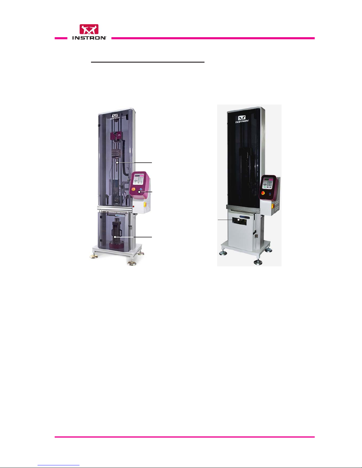
8.2 COMPONENT IDENTIFICATION
In the following pages, a number of figures of the instrument can be found with identification of the main parts.
Fig. 1 - CEAST 9340 7515.000.
General view
Fig. 2 - CEAST 9340 7516.000.
General view
Turret
Test
chamber
Environmental
test chamber
Control
box

Page 40 - CEAST 9340 - Instructions for Use and Maintenance 7510.000MN1r ed. 1 rev . 1
Fig. 3 - View inside turret
Striker lifter (crosshead)
(Automatic striker
recovery/releasing
system)
Photocell
(Optical detector for
impact and rebound
velocity measuring
system)
Flag (Impact and
rebound velocity
measuring system)
Combinable weights
Striker holder
Instrumented striker
Absorber block (x 2)
Ring nut
(Weights locking)
Striker antirebound
system (option)
Dumper (x 2)
(Oleodynamic residual
energy absorbers)

CEAST 9340 - Instructions for Use and Maintenance 7510.000MN1r ed. 1 rev. 1 - Page 41
8.2.1 SAFETIES AND THEIR LOCATIONS
The instrument is equipped with the following safety devices:
1) - Safety thermostat: it intervenes should the temperature of the environmental cham-
ber go over the maximum allowable temperature (over 100°C), cutting the electric
service to the heating resistances. This component is located in the electric box rear
the environmental test chamber.
2) - Safety switch on turret door: this switch is located in the turret near the door lock.
Normal operating condition (Power ON push-button already pressed ).
When you open the door:
• Power ON push-button remains switched on.
• All systems inside the turret are disabled.
• All systems inside the environmental chamber remains enabled.
When you close the door:
• After a few seconds all systems inside the turret are enabled.
3) - Safety switch on standard chamber door (for instruments without environmental
chamber): this switch is located in the chamber near the door lock.
Normal operating condition (Power ON push-button already pressed).
When you open the door:
• Power ON push-button remains switched on.
• All systems inside the turret are disabled.
When you close the door:
• After a few seconds all systems inside the turret are enabled.
4) - Safety switch on environmental chamber door: this switch is located in the chamber
near the door lock.
Normal operating condition (Power ON push-button already pressed).
When you open the door:
• Power ON push-button remains switched on.
• All systems inside the turret are disabled.
• All systems inside the environmental chamber are disabled.
When you close the door:
• After a few seconds all systems inside the turret and the environmental chamber
are enabled and the previous operating conditions are restored.

Page 42 - CEAST 9340 - Instructions for Use and Maintenance 7510.000MN1r ed. 1 rev . 1
5) - Upper and lower limit switches for the automatic striker recovery system: they
intervene and stop the stroke of the striker lifter in the two directions of motion.
These components are located in the turret.
6) - ON-OFF valve: is used to close the compressed air inlet to the instrument and in
the mean time to discharge the pneumatic circuit of the instrument without disconnect the air delivery pipe.
When the on-off valve is in “Closed” position the knob can be padlocked. This solution ensures the maximum safety of the personnel during the maintenance interventions. This component is located rear the instrument.
7) - Pressure switch: it intervene and cut off the power to the instrument when the
pressure of the compressed air goes down below 5 bar.

CEAST 9340 - Instructions for Use and Maintenance 7510.000MN1r ed. 1 rev. 1 - Page 43
8.3 COMMANDS
Main Switch
Located underneath of the control box, it
turns ON (I) or OFF (O) the voltage to the
instrument.
O OFF
I ON
Control box
••
••
• Power ON push-button: enable the auxil-
iary circuits of the instrument and switch
on the light inside the button.
••
••
• Emergency-Stop push-button: under
emergency conditions, it allows immediately to shut off the power to the auxiliary
circuits of instrument.
To restore the controls, rotate the button
about half a turn clockwise, in order to
disengage it from the locked position.
The instrument stays off until the Power
ON push-button is pressed again.
••
••
• "Keypad and Display": the man/machine
interface occurs through the use of the
keyboard and the display . These two components are closely connected and they
are used to program the tests, to command the motorized devices of instrument, to show the results of the test performed and the messages for the operator in case of problems or errors.
The large liquid crystal display allows up
to 80 characters to be shown on 4 rows.

Page 44 - CEAST 9340 - Instructions for Use and Maintenance 7510.000MN1r ed. 1 rev . 1
8.4 OPERATIONS
8.4.1 KEY FUNCTIONS
Here you will find the list of the single keys and next to each one a brief description of
the function it performs.
SPACE1D E F3G H I
4
M N O6P Q R S
7
W X Y Z
9
DESCRIPTION OF FUNCTION
KEY
During Data Input In the Menus During Test
Open and close the specimen
clamping device
Type the alphanumeric characters indicated on the key.
Not activated
Type the alphanumeric characters indicated on the key
Not activatedType the alphanumeric char-
acters indicated on the key
Move UP the striker holder
cross lifter
Not activatedType the alphanumeric charac-
ters indicated on the key
ENTERENTER
ENTER
Delete the last character typed
Confirm the Data lnput
Move DOWN the striker holder
lifter
Page through the default inputs on the display
(e.g.: Y/N)
Select the function where the
cursor is located
Interrupt the test
Not activated
Not activated
Not activated
Return to the previous page /
return to the first page if it is
hold pushed. Skip a function
Type the alphanumeric characters indicated on the key
Not activated
Type the decimal point and the
following character:
_
0
HOME
A B C
2
UP
T U V
8
CLAMP
J K L
5
DOWN
.
PRINT
CANC
STOP
BACK
Page through the data lists on
the display (with autoscroll)
Not activatedNot activated
Start a test or a function
Not activated
Not activated
START
Not activatedNot activated
Not activated
Not activated
Bring the instrument at HOME
Not activated
Not activated
Not activated
Note: in order to enter a numeral on the display, you must only press the key with the
corresponding number. To enter a letter of the alphabet you must continue to
press the key with the corresponding letter until it is shown in the display (the
same method used by mobile phones).

CEAST 9340 - Instructions for Use and Maintenance 7510.000MN1r ed. 1 rev. 1 - Page 45
The programming of the tests is done by typing in the parameters using the keyboard in
the order that they are shown on the display.
After the test cycle is started, the program performs the measurements requested, acquires the data, elaborates it, and automatically supplies the results.
The results obtained can be seen in real time on display.
Note: to facilitate the understanding of the program structure there follows a flowchart
showing its functions in hierarchical order. Each block is identified with the writing
Vid. (Screen) and a progressive number, XXX, that follows the order of appearance on the screen of the display. This order is followed in order to present the
figures during the description of the program.
8.4.2 PROGRAM

Page 46 - CEAST 9340 - Instructions for Use and Maintenance 7510.000MN1r ed. 1 rev . 1
Menu
Utility
Vid. 1.6
Menu
Service
Vid. 1.7
Initial
Screen
Vid. 0
MAIN
MENU
Vid. 1
Start-Up
Screen
Vid. 0.0
Menu
Load
Parameters
Vid. 1.2
Menu
Set
Temperature
Vid. 1.1
Menu
Modify
Parameters
Vid. 1.3
Menu
Save
Parameters
Vid. 1.4
Menu
Results
Vid. 1.5
Parameters
Vid. 1.3 a
Parameters
(other)
Vid. 1.3 b
Input
Password
Vid. 1.6.1
Cycle
Counter
Vid. 1.6.2
FW
Version
Vid. 1.6.3
Modify
Password
Vid. 1.6.4
Clock
Vid. 1.6.5
Language
Vid. 1.6.6
Striker
Release
Vid. 1.7.2
Move to
Height
Vid. 1.7.3
Visualize
Sensors
Vid. 1.7.4
Visualize
I/O
Vid. 1.7.5
Modify
Configuration
Vid. 1.7.6
Modify
Cal.
Parameters
Vid. 1.7.7
Shutter
Moving
Vid. 1.7.1
Representation of the program structure (firmware) in hierarchical order
*
*
(*) Menus used by Service Personnel of ITW Test
and Measurement Italia S.r.l. - INSTRON CEAST
Division only

CEAST 9340 - Instructions for Use and Maintenance 7510.000MN1r ed. 1 rev. 1 - Page 47
Vid. 0 - Initial Screen
CEAST 9340 CEAST 9340
CEAST 9340 CEAST 9340
CEAST 9340
Ver. X.XX Ver. X.XX
Ver. X.XX Ver. X.XX
Ver. X.XX
S.N. XXXXX S.N. XXXXX
S.N. XXXXX S.N. XXXXX
S.N. XXXXX
1
2
3
Vid. 00 - CEAST 9340 Startup Screen
press START for press START for
press START for press START for
press START for
CEAST 9340 startup CEAST 9340 startup
CEAST 9340 startup CEAST 9340 startup
CEAST 9340 startup
8.5 PROGRAM START - UP
The program is automatically started when the Main switch is “ON” and it performs the
following operations
:
• Shows, temporarily , on the display the introduction of the program (see Vid. 0) where the
following information are indicated
: (1) name of the instrument, (2) the firmware version
resident in memory and (3) the serial number.
• After few seconds the screen changes from vid. 0 to vid. 00 visualizing the message
“press START for CEAST 9340 startup”.
Note: before pressing the START key check that the POWER ON button is lit.
• When the operator press the START key the program performs the following operations
and at the end it loads the parameters relative to the last test performed (only if it has
been previously stored on the instrument memory) and it visualizes the main menu (see
Vid. 1).
• Check of safety thermostat operation (for instrument equipped with environmental
chamber only);
• Check of temperature sensor operation (Pt100 ohm type) that measure the tempera-
ture in the chamber (for instrument equipped with environmental chamber only);
• Initialization of specimen clamping system;
• Initialization of environmental chamber shutter (optional).
Note: at the start the instrument the “Password” is set to the previous access level (before
switching it off).

Page 48 - CEAST 9340 - Instructions for Use and Maintenance 7510.000MN1r ed. 1 rev . 1
8.5.1 NAVIGATION THROUGH THE PROGRAM MENUS
Below the method of navigation inside the various program menus using the keyoard is
described.
XXXXXXXXXXXXXXXX
XXXXXXXXXXXXXXXX
XXXXXXXX
XXXXXXXXXXXXXXXX
XXXXXXXXXXXXXXXX
XXXXXXXX
XXXXXXXXXXXXXXXX
XXXXXXXXXXXXXXXX
XXXXXXXX
XXXXXXXXXXXXXXXX
XXXXXXXXXXXXXXXX
XXXXXXXX
Sample Screen
>
- Line 1
- Line 2
- Line 3
- Line 4
When the instrument is switched-on, the firmware performs a number of preliminary
checks on the status of the instrument; the results of this checks can be visualized
selecting the “View Results” option in the “Autocheck” menu, see para. 8.5.21.
After the preliminary check the firmware waits that the operator presses the “Start” key
for starting the automatic zero-set. At the end of the zero-set, the firmware visualizes
the “Main menu” on display.
Note: the zero-set involves the automatic movement of striker holder lifter.
1) Choosing a sub-menu or a function:
••
••
• Move the cursor “>” to the desired row using the
keys.
••
••
• Press the
ENTER
key to open the menu or to perform a function.
2) Modify a parameter:
••
••
• Move the cursor “>” to the row of the parameter you wish to change using the
keys.
a) Modify the alphanumeric parameter using the keys on the keyboard.
b) Modify the parameters of choice (Y / N) using the
or keys.
••
••
• Confirm using the
ENTER
key.
Note: > cursor positioned on a function or parameter that can be chosen or modi-
fied;
cursor positioned on a function, or a parameter, or a comment, that can not
be chosen or modified;
*
parameter being modified. Disappears after the confirmation with the
ENTER
key is given.
Note: rapid, continuous movement of the cursor is available (maintaining pressed the
keys).
The display can visualize only four rows at the same time. If the available list has a
larger number of rows, it is possible to move back and forth using the
keys in
order to see all of the functions or options available.
Note: - In the figures shown in the following pages, all of the rows that make up each
complete data or function list are shown, even if in many cases there are more
than four rows visualized.
Note: - The numbers shown next to the figures are used as explicit references in order
to facilitate the comprehension of the text, but do not appear on the display.

CEAST 9340 - Instructions for Use and Maintenance 7510.000MN1r ed. 1 rev. 1 - Page 49
The “Canc” function can be used in two different ways:
- In case of error during the editing of the parameters, it deletes the last character typed.
- During the test stops the execution.
The “Back” key can be used in two different ways
- Press the key and release it: to exit from the active screen and return to the preceding one;
- Press the key and maintain it pressed: to exit from the active screen and return to the first
screen (main menu).

Page 50 - CEAST 9340 - Instructions for Use and Maintenance 7510.000MN1r ed. 1 rev . 1
Vid. 1 - Main menu of the program
8.5.2 MAIN MENU
XXX mm XXX mm
XXX mm XXX mm
XXX mm
S:XXX.X°CS:XXX.X°C
S:XXX.X°CS:XXX.X°C
S:XXX.X°C
(d)XXX mm (d)XXX mm
(d)XXX mm (d)XXX mm
(d)XXX mm
R:XXX.X°CR:XXX.X°C
R:XXX.X°CR:XXX.X°C
R:XXX.X°C
SET TEMPERATURE SET TEMPERATURE
SET TEMPERATURE SET TEMPERATURE
SET TEMPERATURE
LOAD PARAMETERS LOAD PARAMETERS
LOAD PARAMETERS LOAD PARAMETERS
LOAD PARAMETERS
MODIFY PARAMETERS MODIFY PARAMETERS
MODIFY PARAMETERS MODIFY PARAMETERS
MODIFY PARAMETERS
SAVE PARAMETERS SAVE PARAMETERS
SAVE PARAMETERS SAVE PARAMETERS
SAVE PARAMETERS
RESULTS RESULTS
RESULTS RESULTS
RESULTS
UTILITY UTILITY
UTILITY UTILITY
UTILITY
SERVICE SERVICE
SERVICE SERVICE
SERVICE
>
1
5
4
1) Temperature set (Celsius degree) in the parameters file currently used.
2) Actual temperature (Celsius degree) measured from the temperature sensor in the environmental chamber.
When the conditioning is disabled (or when there is an error, e.g.: thermoregulator
cable detached) the temperature value is visualized as ????.?.
3) Position in millimeter to which the pointer of the optical detector (part of the striker velocity
measuring device) must be set on the rule located in the turret right side (see Fig. below).
The position is automatically calculated from the program according to the striker lenght
and the specimen thickness.
4) Height set of (striker) release.
Note: functions of steps 1, 2, 3 and 4 are not selectable with the cursor.
5) Menu through which it is possible to recall all the functions of the instrument shown on
display . Each function is selectable with the cursor “>” using the
keys and confirmed
with the
ENTER
key.
3
2
Rule
Knob
Photocell
(Optical Detector)
Photocell height adjusting device (ref. step 3)

CEAST 9340 - Instructions for Use and Maintenance 7510.000MN1r ed. 1 rev. 1 - Page 51
1) Switches ON/OFF the environmental chamber. Select using the keys.
2) Allows to set the temperature value for the chamber. The program accepts values from -
50 to 100 °C. Values out of this range are shown as error message.
3) Pressing the START key:
••
••
• if Chamber = OFF: disables the chamber.
••
••
• if Chamber = ON: enables the chamber and start the conditioning to the set
temperature (step 2).
Pressing the BACK key the program returns automatically to the main menu without to
do anything at all.
8.5.4 LOAD P ARAMETERS
Vid. 1.2 - “Load Parameters“
01 yyyyyyyyyyyyyyy01 yyyyyyyyyyyyyyy
01 yyyyyyyyyyyyyyy01 yyyyyyyyyyyyyyy
01 yyyyyyyyyyyyyyy
02 yyyyyyyyyyyyyyy02 yyyyyyyyyyyyyyy
02 yyyyyyyyyyyyyyy02 yyyyyyyyyyyyyyy
02 yyyyyyyyyyyyyyy
03 yyyyyyyyyyyyyyy03 yyyyyyyyyyyyyyy
03 yyyyyyyyyyyyyyy03 yyyyyyyyyyyyyyy
03 yyyyyyyyyyyyyyy
04 yyyyyyyyyyyyyyy04 yyyyyyyyyyyyyyy
04 yyyyyyyyyyyyyyy04 yyyyyyyyyyyyyyy
04 yyyyyyyyyyyyyyy
05 yyyyyyyyyyyyyyy05 yyyyyyyyyyyyyyy
05 yyyyyyyyyyyyyyy05 yyyyyyyyyyyyyyy
05 yyyyyyyyyyyyyyy
.. ....... .....
.. ....... .....
.. .....
25 yyyyyyyyyyyyyyy25 yyyyyyyyyyyyyyy
25 yyyyyyyyyyyyyyy25 yyyyyyyyyyyyyyy
25 yyyyyyyyyyyyyyy
>
1
The menu “Load Parameters” allows to load a group of parameters that has been previously saved. The program is able to memorize up to 25 groups of parameters.
1) The group is selected by the user through the cursor “>” and confirmed with the
ENTER
key.
Pressing the
ENTER
key the selected parameters group is loaded in memory as “Current
Parameters” and the program returns automatically to the main menu (Vid. 1).
8.5.3 SET TEMPERATURE
Vid. 1.1 - Menu “Set Temperature“
THERMO CHAMBER OFFTHERMO CHAMBER OFF
THERMO CHAMBER OFFTHERMO CHAMBER OFF
THERMO CHAMBER OFF
TEMPERATURE[°C] XXXTEMPERATURE[°C] XXX
TEMPERATURE[°C] XXXTEMPERATURE[°C] XXX
TEMPERATURE[°C] XXX
Press START or BACKPress START or BACK
Press START or BACKPress START or BACK
Press START or BACK
>
1
2
3
The menu “Set Temperature” allows to switch ON or OFF the environmental chamber
and to set the temperature for the specimens conditioning and chamber drying.
Note: available only with the environmental chamber configured.
If the conditioning is on, whenever the chamber door is closed, a three-beep acoustic
signal can be heard if the the conditioning is properly restarted. If a long fourth beep is
heard, it means that the restart of the conditioning was not performed: try to open and
close again the chamber door or restart the conditioning by means of the command
Set temperature.

Page 52 - CEAST 9340 - Instructions for Use and Maintenance 7510.000MN1r ed. 1 rev . 1
Vid. 1.3 a - “Parameters“
8.5.5 MODIFY P ARAMETERS
04 yyyyyyyyyyyyyyy04 yyyyyyyyyyyyyyy
04 yyyyyyyyyyyyyyy04 yyyyyyyyyyyyyyy
04 yyyyyyyyyyyyyyy
SUPPORT TYPESUPPORT TYPE
SUPPORT TYPESUPPORT TYPE
SUPPORT TYPE
FF
FF
F
SP. CLAMPINGSP. CLAMPING
SP. CLAMPINGSP. CLAMPING
SP. CLAMPING
DD
DD
D
INPUT H/V/EINPUT H/V/E
INPUT H/V/EINPUT H/V/E
INPUT H/V/E
HH
HH
H
CONDITIONINGCONDITIONING
CONDITIONINGCONDITIONING
CONDITIONING
NN
NN
N
ANTIREBOUNDANTIREBOUND
ANTIREBOUNDANTIREBOUND
ANTIREBOUND
NN
NN
N
OTHER PARAM.OTHER PARAM.
OTHER PARAM.OTHER PARAM.
OTHER PARAM.
>
1
2
3
4
5
Allows the input and modification of the current parameters group. The access is allowed for the user level or higher.
Description of the parameters from (1) to (8):
1) Identify the parameters group last loaded from the menu “Load Parameters” (Vid.
1.2). The field is modifiable: the name entered will be that visualized in the “Parameters groups” list, if the current file will be saved.
2) “Support Type”: it select the type of specimen support (F or V) installed in the test
chamber.
F: fixed height (see para. 8.6.1 Fig. 1);
V: adjustable height (see para. 8.6.2 Fig. 2).
3) “Sp. Clamping”: enable or disables the operation of specimen clamping plate in
three different ways.
D: clamping plate disabled (the specimen is not clamped during the test);
Note: if the clamping plate has been manually operated by the “Clamp” key
before starting the test, the specimen remains clamped until the test is
done. The clamping plate goes up when the test ends and it remains
disabled.
C: clamping plate enabled during the test (the specimen is clamped before test and
unclamped after test).
When the environmental chamber door is open for the specimen replacement,
the systems inside the chamber are switched-off.
When the door is closed again, the systems inside the environmental chamber
will be switched-on after a few seconds.
I: clamping plate enabled during the test (the specimen is clamped before test
and unclamped after test).
This is the
suggested condition for tests at low temperature on films.
When the environmental chamber door is open for the specimen replacement,
the systems inside the chamber are switched-off.
6
7

CEAST 9340 - Instructions for Use and Maintenance 7510.000MN1r ed. 1 rev. 1 - Page 53
When the door is closed again, the systems inside the environmental chamber
will be switched-on after a few seconds.
The clamping plate goes down and clamp the films just before that the fan
is switched-on. This condition avoids the expulsion of film from the specimen
support due to the air flow of the fan.
Note: The “I” option is available only with environmental chamber configured.
4) “Input H/V/E”: select the input type (H, V or E):
H: drop height;
V: impact velocity;
E: energy at the impact.
5) “Conditioning”: it enables (Y) or disables (N) the temperature control of environmen-
tal chamber (if installed and configured in the program). Function not used for standard chamber.
Conditioning N: the test starts when the operator runs it.
Conditioning Y: the test can be run only if the temperature is at the set point (± 1 °C).
6) “Antirebound”: it enables (Y) or disables (N) the striker antirebound system (if in-
stalled and configured in the program).
7) “Other param.”: it goes to the next menu of parameters (see Vid. 1.3 b).

Page 54 - CEAST 9340 - Instructions for Use and Maintenance 7510.000MN1r ed. 1 rev . 1
Vid. 1.3 b - “Parameters (other)“
TEMPERATURETEMPERATURE
TEMPERATURETEMPERATURE
TEMPERATURE
[°C] [°C]
[°C] [°C]
[°C]
+XXX.XX+XXX.XX
+XXX.XX+XXX.XX
+XXX.XX
MASSMASS
MASSMASS
MASS
[Kg][Kg]
[Kg][Kg]
[Kg]
XX.XXX.X
XX.XXX.X
XX.X
DROP HEIGHTDROP HEIGHT
DROP HEIGHTDROP HEIGHT
DROP HEIGHT
[mm][mm]
[mm][mm]
[mm]
XXXXXX
XXXXXX
XXX
VELOCITYVELOCITY
VELOCITYVELOCITY
VELOCITY
[m/s][m/s]
[m/s][m/s]
[m/s]
XX.XXXX.XX
XX.XXXX.XX
XX.XX
ENERGYENERGY
ENERGYENERGY
ENERGY
[J][J]
[J][J]
[J]
XX.XXX.X
XX.XXX.X
XX.X
STRIKER LENGTHSTRIKER LENGTH
STRIKER LENGTHSTRIKER LENGTH
STRIKER LENGTH
[mm][mm]
[mm][mm]
[mm]
XXXXXX
XXXXXX
XXX
SPECIMEN OFFSETSPECIMEN OFFSET
SPECIMEN OFFSETSPECIMEN OFFSET
SPECIMEN OFFSET
[mm][mm]
[mm][mm]
[mm]
XX.X
XX.X
XX.XXX.X
XX.X
IMPACT OFFSETIMPACT OFFSET
IMPACT OFFSETIMPACT OFFSET
IMPACT OFFSET
[mm][mm]
[mm][mm]
[mm]
XXXXXX
XXXXXX
XXX
>
9
10
11
12
13
9) “Temperature”: is the test temperature to which the environmental chamber is cooled
(negative value) or heated (positive value).
Parameter shown only if the “Conditioning” parameter (see Vid. 1.3 a) is selected “Y”.
10) “Mass”: is the total mass used for the impact test. It is equal to the sum of the
following weights: striker, striker holder, striker extension (if installed) and additional
weights (if installed).
11) “Drop Height”: is the height from which the striker is released for the impact test.
Parameter shown only if the “Input H/V/E” parameter (see Vid. 1.3 a) is selected “H”.
12) “Velocity”: is the velocity at which the striker strikes the specimen.
Parameter shown only if the “Input H/V/E” parameter (see Vid. 1.3 a) is selected “V”.
13) “Energy”: is the energy at the impact.
Parameter shown only if the “Input H/V/E” parameter (see Vid. 1.3 a) is selected “E”.
14) “Striker Length”: is the length of the striker used for the tests plus the striker exten-
sion (if installed).
Note: if the entered striker length value is wrong, it can cause a wrong striker positioning with a consequent error when carry out test. Moreover it can cause a collision between the striker and lubricating system (if this last one is installed).
15) “Specimen Offset”: is the thickness of the specimen under test.
Parameter shown only if the “Support Type” p arameter (see Vid. 1.3 a) is selected “F”.
16) “Impact Offset”: is the distance between the nominal impact plane and the speci-
men surface.
Parameter shown only if the “Support T ype” p arameter (see Vid. 1.3 a) is selected “V”.
14
15
16

CEAST 9340 - Instructions for Use and Maintenance 7510.000MN1r ed. 1 rev. 1 - Page 55
Drop
Height
Nominal
Impact
Plane
Drop
Height
Impact
Offset
Specimen
Tickness
Sketches referred to the steps: 11) Drop Height, 14) Specimen Thickness and 15) Impact Offset
Fixed height
stand
Adjustable
height stand
Note: all the parameters are shown on two rows:
• First row: name of the parameter.
• Second row: value (modifiable) and unit of measure (not modifiable).
Note: the “minimum and maximum limits” of the parameters attributes and the “unit of
measure” of each parameter are indicated in the table “Test Parameters” on the
next page.
Note: the instructions for typing the parameters are shown in chapters 8.4.2.
Note: for further technical data related to the “striker antirebound system” make refer-
ence to the “Appendix H“.
Test Parameters
Measure
Units
Input
Format
Limits
Min. Max.
Temperature
[°C]
-50 100
+/-xx
[kg]
[mm]
[m/s]
[mm]
[mm]
[mm]
Mass
Velocity
Striker Length
Specimen Thickness
Impact Offset
Drop Height
0.9 40
30 1100
0,77
4.64
239
370
0
25
- 120 + 100
xxxxx
xx.xx
xxx
xx.x
+/-xx
xx.xx

Page 56 - CEAST 9340 - Instructions for Use and Maintenance 7510.000MN1r ed. 1 rev . 1
8.5.7 RESULTS
V:xx.x m/s Vr:xx.x m/sV:xx.x m/s Vr:xx.x m/s
V:xx.x m/s Vr:xx.x m/sV:xx.x m/s Vr:xx.x m/s
V:xx.x m/s Vr:xx.x m/s
CL AR +xx °CCL AR +xx °C
CL AR +xx °CCL AR +xx °C
CL AR +xx °C
xxxx mm xx.x m/sxxxx mm xx.x m/s
xxxx mm xx.x m/sxxxx mm xx.x m/s
xxxx mm xx.x m/s
M:xx.x kg E:xxxx JM:xx.x kg E:xxxx J
M:xx.x kg E:xxxx JM:xx.x kg E:xxxx J
M:xx.x kg E:xxxx J
>
8.5.6 SA VE P ARAMETERS
Vid. 1.4 - “Save Parameters“
01 yyyyyyyyyyyyyyy01 yyyyyyyyyyyyyyy
01 yyyyyyyyyyyyyyy01 yyyyyyyyyyyyyyy
01 yyyyyyyyyyyyyyy
02 yyyyyyyyyyyyyyy02 yyyyyyyyyyyyyyy
02 yyyyyyyyyyyyyyy02 yyyyyyyyyyyyyyy
02 yyyyyyyyyyyyyyy
03 yyyyyyyyyyyyyyy03 yyyyyyyyyyyyyyy
03 yyyyyyyyyyyyyyy03 yyyyyyyyyyyyyyy
03 yyyyyyyyyyyyyyy
04 yyyyyyyyyyyyyyy04 yyyyyyyyyyyyyyy
04 yyyyyyyyyyyyyyy04 yyyyyyyyyyyyyyy
04 yyyyyyyyyyyyyyy
05 yyyyyyyyyyyyyyy05 yyyyyyyyyyyyyyy
05 yyyyyyyyyyyyyyy05 yyyyyyyyyyyyyyy
05 yyyyyyyyyyyyyyy
.. ....... .....
.. ....... .....
.. .....
25 yyyyyyyyyyyyyyy25 yyyyyyyyyyyyyyy
25 yyyyyyyyyyyyyyy25 yyyyyyyyyyyyyyy
25 yyyyyyyyyyyyyyy
>
1
The menu “Save Parameters” allows to save a group of parameters that has been
previously modified.
1) The group position is selected by the user through the cursor “>” and saved with the
ENTER
key.
Note: the program overwrites the current set to the selected group.
After the save the program return to the “Main menu”.
This menu visualizes the values related to the last performed test (if performed)
1) “V”: velocity of the striker impact measured from the optical detector.
2) “Vr”: velocity of the striker rebound measured from the optical detector
3) “CL”: it is visualized only if the “clamping” option is configured and activated.
4) “AR”: it is visualized only if the “antirebound” option is configured and activated.
4) “+xx °C”: this field shows the test temperature (only if the environmental chamber is
configured and the conditioning is activated).
5) “xxxx mm”: it is the drop height value (parameter “H”, see Vid. 1.3 a).
6) “xx.x m/s”: it is the expected velocity.
7) “M: xx.x kg”: it is the dropping mass.
8) “E: xxxx J”: it is the potential energy.
Vid. 1.5 - Menu “Results“

CEAST 9340 - Instructions for Use and Maintenance 7510.000MN1r ed. 1 rev. 1 - Page 57
1) “Input Password”: insert the password to access the “User” or “Service” function
level.
2) “Cycle Counter”: shows the number of test cycles performed by the instrument with
the possibility to zero it for a partial indication.
3) “FW Version”: indication of the firmware installed and the configuration of the instru-
ment.
4) “Modify Password”: to modify the password set for the “User” level.
5) “Clock”: function for setting the time and date.
6) “Language”: select the language preferred by the user.
Vid. 1.6 - Menu “Utility“
8.5.8 UTILITY
INPUT PASSWORDINPUT PASSWORD
INPUT PASSWORDINPUT PASSWORD
INPUT PASSWORD
CYCLE COUNTERCYCLE COUNTER
CYCLE COUNTERCYCLE COUNTER
CYCLE COUNTER
FW VERSIONFW VERSION
FW VERSIONFW VERSION
FW VERSION
MODIFY PASSWORDMODIFY PASSWORD
MODIFY PASSWORDMODIFY PASSWORD
MODIFY PASSWORD
CLOCKCLOCK
CLOCKCLOCK
CLOCK
LANGUAGELANGUAGE
LANGUAGELANGUAGE
LANGUAGE
>

Page 58 - CEAST 9340 - Instructions for Use and Maintenance 7510.000MN1r ed. 1 rev . 1
Vid. 1.6.1 - “Input Password“
8.5.9 INPUT PASSWORD
Password ********Password ********
Password ********Password ********
Password ********
“Password”: allows to type-in the password for different access to the program. After
the input, the program shows the message with the access level.
Press the
BACK
key to return to the “Main Menu” (Vid. 1).
Letters and numbers can be used up to a maximum of 8 characters.
The instrument can work at three different access levels:
• Operator (without Password): can perform tests on the instrument using existing
parameter groups but cannot modify them (the groups can be loaded using the
proper function).
• User (with Password): can perform tests on the instrument using the existing parameter groups, can access the parameter groups for modification and can modify
the Password using the “Modify Password” function (Vid. 1.6.4).
• Service (with Password): can access to all the menus and functions.
To return to the “Operator” level from the “User” or “Service” levels, type 0 (zero) in the
“Password” field.
>
Note: the program maintains in memory the current password level.
If you switches the instrument off from the “User” level, on the next restart the
firmware remains on the “User” level.
If you want to restart as “Operator” level instead the “User” one, you must change
it before to switch the instrument off.

CEAST 9340 - Instructions for Use and Maintenance 7510.000MN1r ed. 1 rev. 1 - Page 59
Vid. 1.6.3 - “Firmware Version“
8.5.1 1 FW VERSION
1) “FW REV. X.XX”: number of the program version installed on the instrument.
2) “LD REV. X.XX”: number of the boot loader version.
3) “CONF. 16 - 9”: configuration of the instrument.
4) “CONF. 8 - 1”: configuration of the instrument:
“A” Environmental Chamber
“B” Striker Antirebound System
FW REV.FW REV.
FW REV.FW REV.
FW REV.
XX.XX XX.XX
XX.XX XX.XX
XX.XX
LD REV.LD REV.
LD REV.LD REV.
LD REV.
XX.XX XX.XX
XX.XX XX.XX
XX.XX
CONF.16-9CONF.16-9
CONF.16-9CONF.16-9
CONF.16-9
00000000 00000000
00000000 00000000
00000000
CONF.8-1 00000011CONF.8-1 00000011
CONF.8-1 00000011CONF.8-1 00000011
CONF.8-1 00000011
>
AB
1) “ENTER to Reset”: message for the user, pushing the
0
HOME
key the partial cycle (or tests)
counter is zeroed.
2) “Par. Cycles”: shows the number of cycles (or tests) run by the instrument prior to
zeroing.
3) “Tot. Cycles”: indicates the total number of cycles (or tests) performed by the instrument.
4) “Press BACK”: return to the previous page.
Vid. 1.6.2 - “Cycle Counter“
8.5.10 CYCLE COUNTER
ENTER to ResetENTER to Reset
ENTER to ResetENTER to Reset
ENTER to Reset
PAR. CYCLESPAR. CYCLES
PAR. CYCLESPAR. CYCLES
PAR. CYCLES
XXXXXX
XXXXXX
XXX
TOT. CYCLESTOT. CYCLES
TOT. CYCLESTOT. CYCLES
TOT. CYCLES
XXXXXX
XXXXXX
XXX
Press BACKPress BACK
Press BACKPress BACK
Press BACK
>
Note: bit value: 1 installed; 0 not installed.

Page 60 - CEAST 9340 - Instructions for Use and Maintenance 7510.000MN1r ed. 1 rev . 1
Vid. 1.6.5 - “Clock“
8.5.13 CLOCK
>
YEAR YEAR
YEAR YEAR
YEAR
XXXXXXXX
XXXXXXXX
XXXX
MONTH MONTH
MONTH MONTH
MONTH
XXXX
XXXX
XX
DAYDAY
DAYDAY
DAY
XXXX
XXXX
XX
HOURHOUR
HOURHOUR
HOUR
XXXX
XXXX
XX
MIN.MIN.
MIN.MIN.
MIN.
XXXX
XXXX
XX
SEC.SEC.
SEC.SEC.
SEC.
XXXX
XXXX
XX
APPLYAPPLY
APPLYAPPLY
APPLY
Function used to see the actual clock value and to modify the time and date.
After the modification select the function “Apply” and confirm it using the
ENTER
key to
make the change operative.
Vid. 1.6.4 - “Modify Password“
8.5.12 MODIFY P ASSWORD
>
PASSWORD PASSWORD
PASSWORD PASSWORD
PASSWORD
****************
****************
********
REPEAT REPEAT
REPEAT REPEAT
REPEAT
****************
****************
********
Function used to modify the password for the “User” level.
1) “Password”: type a new password.
Letters and numbers, up to 8 characters maximum, can be used.
2) “Repeat”: re-type the same new password as a check.
The new password will be activated after confirmation with the
BACK
key.
Note: the default password installed is: USER.

CEAST 9340 - Instructions for Use and Maintenance 7510.000MN1r ed. 1 rev. 1 - Page 61
Vid. 1.7 - Menu “Service“
SHUTTER MOVING SHUTTER MOVING
SHUTTER MOVING SHUTTER MOVING
SHUTTER MOVING
STRIKER RELEASESTRIKER RELEASE
STRIKER RELEASESTRIKER RELEASE
STRIKER RELEASE
MOVE TO HEIGHT MOVE TO HEIGHT
MOVE TO HEIGHT MOVE TO HEIGHT
MOVE TO HEIGHT
VISUALIZE SENSORSVISUALIZE SENSORS
VISUALIZE SENSORSVISUALIZE SENSORS
VISUALIZE SENSORS
VISUALIZE I/OVISUALIZE I/O
VISUALIZE I/OVISUALIZE I/O
VISUALIZE I/O
MODIFY CONFIGURATIONMODIFY CONFIGURATION
MODIFY CONFIGURATIONMODIFY CONFIGURATION
MODIFY CONFIGURATION
MODIFY CAL. PARAMET.MODIFY CAL. PARAMET.
MODIFY CAL. PARAMET.MODIFY CAL. PARAMET.
MODIFY CAL. PARAMET.
This menu allows the access to various Service functions. Some of these are protected
by a Password and cannot be accessed by the user. They are exclusively used by ITW
Test and Measurement Italia S.r.l. - INSTRON CEAST Division personnel for setup and
Service.
Press the
BACK
key to return to the previous screen.
8.5.15 SERVICE
>
Vid. 1.6.6 - “Language“
8.5.14 LANGUAGE
>
ITALIANOITALIANO
ITALIANOITALIANO
ITALIANO
ENGLISHENGLISH
ENGLISHENGLISH
ENGLISH
ESPANOLESPANOL
ESPANOLESPANOL
ESPANOL
FRANCAISFRANCAIS
FRANCAISFRANCAIS
FRANCAIS
DEUTSCHDEUTSCH
DEUTSCHDEUTSCH
DEUTSCH
Function used to change the language that is used for the information on the display.
The modification is performed immediately upon confirmation.

Page 62 - CEAST 9340 - Instructions for Use and Maintenance 7510.000MN1r ed. 1 rev . 1
Vid. 1.7.1 - “Shutter moving“
-SHUTTER- -SHUTTER-
-SHUTTER- -SHUTTER-
-SHUTTER-
Press UP to OPENPress UP to OPEN
Press UP to OPENPress UP to OPEN
Press UP to OPEN
Press DOWN to CLOSEPress DOWN to CLOSE
Press DOWN to CLOSEPress DOWN to CLOSE
Press DOWN to CLOSE
The shutter is located only in the environmental chamber and open or close the passage for the striker.
Press the “UP” key to open the shutter or press the “DOWN” key to close it.
Note: the shutter must be open during the drying of the chamber.
8.5.16 SHUTTER MOVING
Vid. 1.7.2 - “Striker Release“
STRIKER RELEASE STRIKER RELEASE
STRIKER RELEASE STRIKER RELEASE
STRIKER RELEASE
Press START or BACKPress START or BACK
Press START or BACKPress START or BACK
Press START or BACK
Press the “ST AR T” key to release the striker or the “BACK” key to return to the previous
screen without release the striker.
8.5.17 STRIKER RELEASE
Note: function visualized only with environmental chamber configured.

CEAST 9340 - Instructions for Use and Maintenance 7510.000MN1r ed. 1 rev. 1 - Page 63
Vid. 1.7.3 - “Move to Height“
OFP/OFQi: show the specimen offset or impact offset set in the current parameters set.
LP: show the length of the striker used for the tests, plus the striker extension (if in-
stalled) set in the current parameters set.
Note: if the entered striker length value is wrong, it can cause a wrong striker positioning with a consequent error when carry out test. Moreover it can cause a collision between the striker and lubricating system (if this last one is installed).
Type Zt/Hc and Height: select and enter the chosen position of the crosshead (Zt selected) or the striker edge (Hc selected).
Zt is referred to the distance between the lower end of the striker holder and the
upper surface of the turret base.
Hc is referred to the distance between the lower end of the striker and the impact
point, and it depends from the test parameters.
Press the
START
key to start the positioning or the
BACK
key to go back without carry out
the positioning.
8.5.18 MOVE TO HEIGHT
>
Vid. 1.7.4 - “Visualize Sensors“
CROSSHEAD HE CROSSHEAD HE
CROSSHEAD HE CROSSHEAD HE
CROSSHEAD HE
XXXX.XXXXX.X
XXXX.XXXXX.X
XXXX.X
SET. P. TEMP.SET. P. TEMP.
SET. P. TEMP.SET. P. TEMP.
SET. P. TEMP.
XX.X XX.X
XX.X XX.X
XX.X
MEASURED TEMP.XXX MEASURED TEMP.XXX
MEASURED TEMP.XXX MEASURED TEMP.XXX
MEASURED TEMP.XXX
Visualize in real time the values measured by sensors.
1) Absolute crosshead height [mm];
2) Temperature set [°C] (*);
3) Temperature measured [°C] in the environmental chamber (*).
(*): only with environmental chamber.
8.5.19 VISUALIZE SENSORS
>
OFP=X.XOFP=X.X
OFP=X.XOFP=X.X
OFP=X.X
LP=XXXLP=XXX
LP=XXXLP=XXX
LP=XXX
TYPE Zt/HcTYPE Zt/Hc
TYPE Zt/HcTYPE Zt/Hc
TYPE Zt/Hc
ZZ
ZZ
Z
HEIGHTHEIGHT
HEIGHTHEIGHT
HEIGHT
XXXXXX
XXXXXX
XXX
Press START or BACKPress START or BACK
Press START or BACKPress START or BACK
Press START or BACK

Page 64 - CEAST 9340 - Instructions for Use and Maintenance 7510.000MN1r ed. 1 rev . 1
Error codes are shown on display and advise the user when an error occurs, see the
Error Codes List in the Appendix G.
8.5.22 ERROR CODES IN THE PROGRAM
8.5.21 EMERGENCIES SYNOPTIC
The table below describes the alarm conditions which can be visualized on display.
Emergencies Synoptic
6 5 4 3 2 1
Temperature
too high/low
Safety
thermostat
alarm
Upper
door
open
Lower
door
open
Power
cut off
Lifter
motor
overload
Vid. 1.7.6 - Example of “alarm visualization“
***ERROR N.205*** ***ERROR N.205***
***ERROR N.205*** ***ERROR N.205***
***ERROR N.205***
EM. STAT. -----*--**EM. STAT. -----*--**
EM. STAT. -----*--**EM. STAT. -----*--**
EM. STAT. -----*--**
PRESS STOP TO ABORTPRESS STOP TO ABORT
PRESS STOP TO ABORTPRESS STOP TO ABORT
PRESS STOP TO ABORT
ENTER TO IGNOREENTER TO IGNORE
ENTER TO IGNOREENTER TO IGNORE
ENTER TO IGNORE
The alarm conditions are visualized as 10 screen fonts consisting of asterisks and underscore lines.
Example: _ _ _ _ _ _ _ _ _ _ 10 underscore lines means no one alarm;
* _ _ _ _ * * _ _ _ 3 asterisks means 3 different active alarms. The alarms
are numbered in increasing order starting from right
to left.
Alarm10Alarm5Alarm
4
Vid. 1.7.5 - “Visualize I/O“
IN 16-9-*****-- IN 16-9-*****--
IN 16-9-*****-- IN 16-9-*****--
IN 16-9-*****--
IN 8-1IN 8-1
IN 8-1IN 8-1
IN 8-1
**--*--***--*--*
**--*--***--*--*
**--*--*
OUT 16-9--**--OUT 16-9--**--
OUT 16-9--**--OUT 16-9--**--
OUT 16-9--**--
OUT 8-1*-*---* OUT 8-1*-*---*
OUT 8-1*-*---* OUT 8-1*-*---*
OUT 8-1*-*---*
Visualize in real time the input/output status: * active; - inactive, see also the Input and
Output lists in the Appendix E and F.
8.5.20 VISUALIZE I/O
>

CEAST 9340 - Instructions for Use and Maintenance 7510.000MN1r ed. 1 rev. 1 - Page 65
8.6 PREPARING THE INSTRUMENT FOR TESTING
8.6.1 REPLACEMENT OF THE STANDS
Authorized Personnel: Operator
Note: stands for CEAST 9340 are mainly of two different types as shown in the figures
below. The stands (Fig. 1 and 2) can be installed indiferrently both in the standard
(ambient temperature) chamber and in the environmental one.
Both stands have the same base to facilitate the replacement operations.
X
X
a) Open the door of the chamber.
b) Loosen and remove the Allen screws.
c) Loosen and remove the shoulder screw.
d) Lift manually the stand for about 2 cm just to disengage it from the centering hub and
then remove (with precaution) the stand from the chamber.
CAUTION ! (for environmental chamber only): before replace the stands make sure
that the environmental chamber is at room temperature.
X
X
DISASSEMBLY
Fig. 1 - Fixed height stand
Fig. 2 - Adjustable height stand
Allen screws
and
flat washers
Shoulder
screw
X
X
X
X
ASSEMBLY
a) Open the door of the chamber.
b) Place (with precaution) the stand in the chamber. Lift it manually of about 2 cm and
engage it on the centering hub.
c) Turn the stand (if necessary) and visually align the hole for the shoulder screw.
d) Tighten the shoulder screw.
e) Tighten the Allen screws.
X

Page 66 - CEAST 9340 - Instructions for Use and Maintenance 7510.000MN1r ed. 1 rev . 1
8.6.2 REPLACEMENT OF THE SPECIMEN FIXTURES
Authorized Personnel: Operator
X
X
Clamping
ring
Screw
X
X
CAUTION ! (for environmental chamber only): before replace the fixtures make sure
that the environmental chamber is at room temperature.
When this is not possible, use a pair of thermally insulating gloves.
Note: for the specimen fixtures list refer to the Appendix A at the end of this document.
8.6.2.1 SPECIMEN FIXTURES FOR FIXED HEIGHT STAND
DISASSEMBLY
8.6.2.1.1
FIXTURES FOR PLATES AND FILMS
Screw
Fixed height
stand
Specimen
fixture
Clamping
plate
Clamping ring
(face toward the
clamping plate)
Pin (x3)
a) Choose the correct specimen fixture
and clamping ring according to the
specimen shape, dimension and stan-
dard of reference (see Appendix A).
b) Open the door of the chamber.
c) Place the clamping ring against the
clamping plate inserting the pins in the
slots.
d) Turn the clamping ring of a quarter of
turn approx..
e) Fasten the clamping ring with screw.
f) Place the specimen fixture on top of
the fixed height stand and fasten it
with the screw.
g) Place and visually center the speci-
men onto the specimen fixture on top
of the fixed height stand.
a) Open the door of the chamber.
b) Loosen the screw on the fixed height
stands.
c) Lift and remove the specimen fixture.
d) Loosen the screw on the clamping
plate.
e) Turn the clamping ring until the pins are
aligned with the slots and remove it from
its seat.
ASSEMBLY
X
X
X
X
X
X
X
X

CEAST 9340 - Instructions for Use and Maintenance 7510.000MN1r ed. 1 rev. 1 - Page 67
8.6.2.1.2 FIXTURE FOR CHARPY TEST
Fig. 1 - Fixture for Charpy test with shoulders according to ASTM standards
(notched plastic specimen)
Fig. 1 A - Fixture configured for test
Fig. 1 B - Fixture with shoulders separate
Fig. 1 C - Shoulder
Adjustable
block
Screw
Reference
plane
Specimen
thickness
3.17 mm
6.35 mm
12.7 mm
Notch
downward
Notch
centering pin
Plastic specimen
Shoulder (x 2)
Locking ring
Slide movement
knob
Shoulder (x 2)
Shoulder screw (x 2)

Page 68 - CEAST 9340 - Instructions for Use and Maintenance 7510.000MN1r ed. 1 rev . 1
Fig. 2 - Fixture for Charpy test with shoulders according to ASTM E-23 standard
(notched metallic specimen)
Fig. 3 - Fixture for Charpy test with shoulders according to ISO standards
(notched and unnotched plastic specimens)
Fig. 3 A - Notched
specimen
Fig. 3 B - Unnotched
specimen
Stop plate
Screw
Notch
downward
Notch
centering pin
Metallic
specimen
Notch
downward
Notch
centering pin
Plastic
specimen
Plastic
specimen
Alignment
pin (x 2)
Alignment
pin (x 2)

CEAST 9340 - Instructions for Use and Maintenance 7510.000MN1r ed. 1 rev. 1 - Page 69
X
X
DISASSEMBLY
a) Open the door of the chamber.
b) Loosen the screw on the fixed height stands (see fig. below).
c) Lift and remove the Charpy test fixture.
X
a) Choose the correct pair of shoulders according to the specimen dimensions and stan-
dard of reference (see Appendix I and previous Fig. 1, 2 and 3).
b) Remove the two shoulder screws fastening the shoulders (see fig. 1 B).
c) Lift and remove the shoulders from the fixture and replace them with the choosen
ones.
d) Fasten the specimen shoulders with shoulder screws.
e)
For shoulders according to ASTM standards (notched plastic specimen) only:
- Loosen the screws fastening the adjustable blocks (see fig. 1 C);
- Align the reference plane of blocks with the line of the specimen thickness: 3.17,
6.35, 12.7 [mm];
- Tighten the screws fastening the adjustable blocks.
f)
For shoulders according to ISO standards (notched plastic specimen) only:
- Check that the stop plate is turned downward (see fig. 3 A).
g)
For shoulders according to ISO standards (unnotched plastic specimen) only:
- Check that the stop plate is turned upward and secured with screw (see fig. 3 B).
ASSEMBLY
Specimen shoulders
X
X
Screw
Fixed height
stand
Clamping plate
without clamp-
ing ring
X
X
X
X
Note: verify that the clamping plate is with-
out clamping ring (see fig. to the right).
h) Place the Charpy test fixture on top of
the fixed height stand.
i) Turn the Charpy test fixture until the pin
enter in the slot of the stand. This pin al-
low to find quickly the correct position of
the fixture.
j)Fasten the Charpy test fixture with screw.
Charpy Test Fixture
k) Place the specimen (notched specimen with notch downward) against the adjustable
blocks (fig. 1 A) or against the alignment pins (fig. 2 or 3 A).
Push the notch centering pin forward and center the notch.
For unnotched specimen use the stop plate.
Specimen
X
X
X
X
X

Page 70 - CEAST 9340 - Instructions for Use and Maintenance 7510.000MN1r ed. 1 rev . 1
X
X
X
X
DISASSEMBLY
8.6.2.1.3 FIXTURE FOR IZOD TEST
a) Choose the correct specimen adapter
according to the specimen dimensions
and standard of reference (see Appendix A).
b) Place the Izod test fixture on a table,
loosen the specimen clamping screw
until the bracket can be lifted allowing to remove the specimen adapter.
c) Remove the two screws fastening the
specimen adapter. They are located
under the Izod test fixture.
d) Lift and remove the specimen adapter
from its seat and replace it with the
choosen one.
e) Fasten the specimen adapter with screws.
a) Open the door of the chamber.
b) Loosen the screw on the fixed height
stands.
c) Lift and remove the Izod test fixture.
ASSEMBLY
X
X
X
X
X
Notch
centering
blade
Specimen
adapter
Specimen
clamping
screw
Specimen
(edgewise
position,
notch
upward)
Screw
Fixed height
stand
Clamping plate
without clamp-
ing ring
Izod test
fixture
Note: verify that the clamping plate is
without clamping ring.
f) Place the Izod test fixture on top of
the fixed height stand.
g) Turn the Izod test fixture until the pin
enter in the slot of the stand. This pin
allow to find quickly the correct position of the fixture.
h) Fasten the Izod test fixture with screw.
Specimen Adapter
Izod Test Fixture
Specimen
clamping
bracket
i) Lift the specimen clamping bracket, insert the specimen (notch upward) in
the slot of the specimen adapter and center the notch using the notch centering blade.
j) Clamp the specimen with the clamping screw.
Specimen
X
X
X
X

CEAST 9340 - Instructions for Use and Maintenance 7510.000MN1r ed. 1 rev. 1 - Page 71
8.6.2.2 SPECIMEN FIXTURES FOR ADJUSTABLE HEIGHT STAND
Note: for the specimen fixtures list refer to the Appendix A at the end of this document.
Note: before to install any specimen fixtures on the adjustable height stand make sure
that the fixtures adapter is already installed on it.
X
DISASSEMBLY
8.6.2.2.1
FIXTURES ADAPTER
ASSEMBLY
X
X
Fixtures
adapter
Adjustable
height stand
a) Open the door of the chamber.
b) Loosen the screw.
c) Lift and remove the fixture adapter
from the adjustable height stand.
a) Open the door of the chamber.
b) Place the fixtures adapter on top of
the adjustable height stand and engage the pin in the underlying hole.
c) Tighten the screw.
X
X
X
Note: before to install the “thousand holes plate” remove the fixtures adapter from the
adjustable height stand.
Screw

Page 72 - CEAST 9340 - Instructions for Use and Maintenance 7510.000MN1r ed. 1 rev . 1
8.6.2.2.2 FIXTURES FOR PLATES, FILMS, CHARPY AND IZOD TESTS
Note: for the disassembly procedures follow the instructions of paras. 8.6.2.1.1
or 8.6.2.1.2 or 8.6.2.1.3.
DISASSEMBLY
Note: the handles of the adjustable height stand are used to adjust the height (upward
or downward) of the specimen fixture and to lock it in the chosen position.
Clamping
ring
Fixtures
adapter
Screw
Adjustable
height stand
Specimen
fixture
Clamping
plate
Screw
Adjustable
height stand
Clamping plate
without
clamping ring
Fixtures
adapter
Screw
For plates and films
For Charpy and Izod tests
ASSEMBLY
X
a) At the end of the assembly operation (fixtures for plates, films, Charpy or
Izod tests) and with the test specimen already installed on the fixture, procede
to determine the height between the upper surface of the specimen and the
end of the striker.
b) Unlock the locking handles.
c) Completely lower the adjustable height stand using the height adjustment
handles.
d) Go to the “Service” menu (para. 8.5.14).
e) Select the “Move to height” fuction (para. 8.5.17).
f) Carry out the following calculation:
X = Striker height [mm] - 134 [mm] + Impact offset [mm];
where:
“Striker height” = 239 to 370 [mm];
“Impact offset” = -120 to 100 [mm].
X
X
X
X
Note: for the assembly procedures follow the instructions of paras. 8.6.2.1.1
or 8.6.2.1.2 or 8.6.2.1.3.
Height
adjustment
handles
Locking handles
X

CEAST 9340 - Instructions for Use and Maintenance 7510.000MN1r ed. 1 rev. 1 - Page 73
g) Enter the calculated value “X” as “Crosshead Position (z)” parameter in the
“Move to height” function (see para. 8.5.17).
h) Alternative mode to paras. f) plus g): enter “0” (zero) as “Striker Position”
(Hc parameter, see para. 8.5.17).
i) Press the “Start” key to positioning the striker.
j) Adjust the height of the stand until the specimen surface touches the striker
end.
k) Lock the stand using the locking handles.
l) Press the “Home” key to move the striker at the rest position.
X
X
X
X
X
X

Page 74 - CEAST 9340 - Instructions for Use and Maintenance 7510.000MN1r ed. 1 rev . 1
8.6.3 REPLACEMENT OF THE STRIKER HOLDER
Authorized Personnel: Operator
Note: for the striker holders weights refer to the tables of para. 8.6.4.
DISASSEMBLY
X
X
a) Release the striker using the proper command under “Service Menu”.
b) Open the front door of the turret accessing to the lifting system, using the special key
provided.
c) Remove the screw fastening the guide plate on the upper left side of the striker
holder and remove manually the guide plate moving the striker holder.
d) Remove the striker holder from the guide columns of the instrument and place it on a
table.
Fig. 1
Standard striker holder
Fig. 2
Light striker holder
X
- Check that the striker holder is free from weights and striker.
- Fasten the harmonic wire eyelet to the striker holder using the screw and washer
shown in the details below. The eyelet is normally removed when change the striker
holder with the light one or when store the striker holder inside the wooden box (option).
X
X
Harmonic wire
eyelet
Screw
X
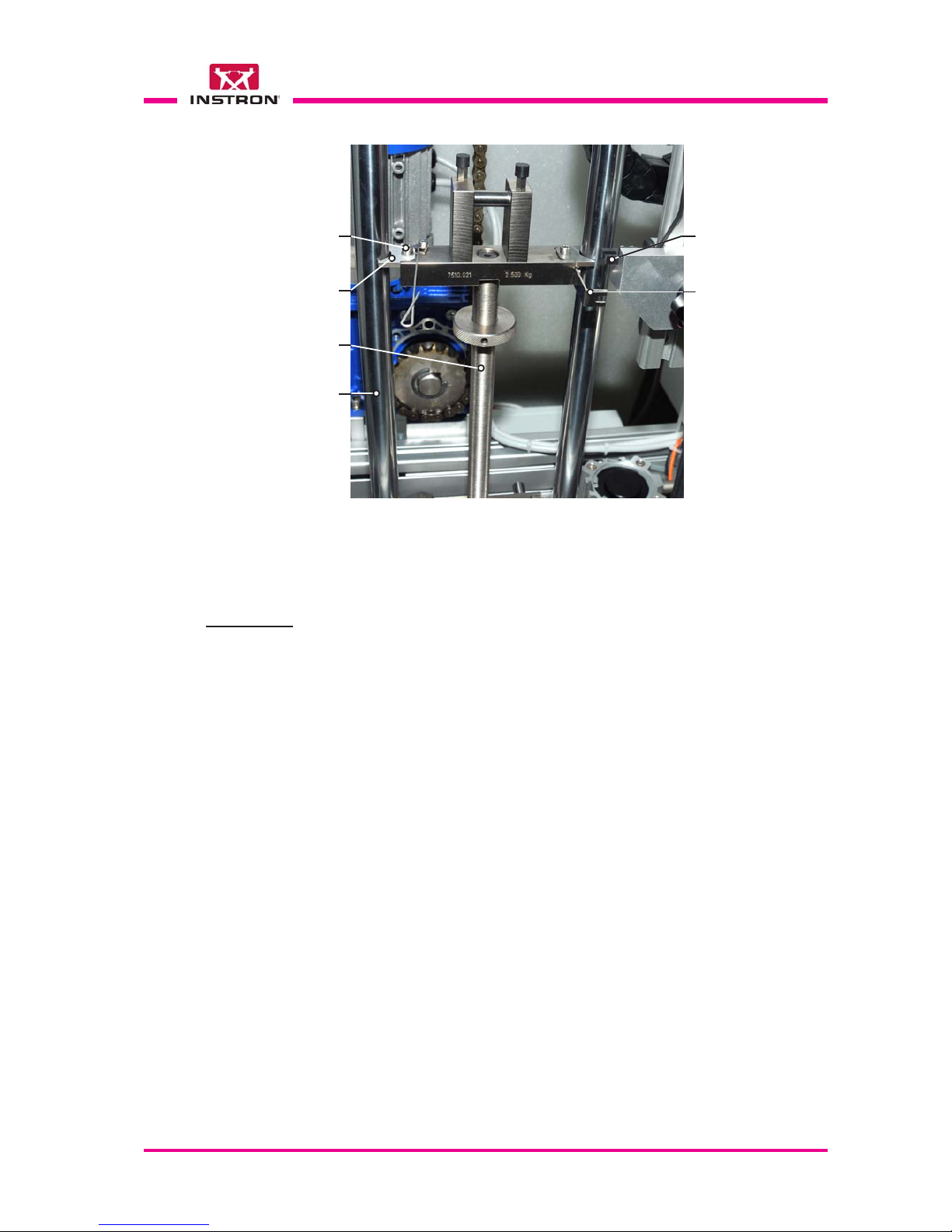
CEAST 9340 - Instructions for Use and Maintenance 7510.000MN1r ed. 1 rev. 1 - Page 75
ASSEMBLY
X
a) Open the front door of the turret accessing to the lifting system, using the special key
provided.
b) Choose the correct striker holder according to the specimen type, dimension and
standard of reference. Striker holder can be of two different types: light (Fig. 2) or
standard (Fig. 1).
c) Check that the striker holder is free from combinable weights and striker.
d) Place the striker holder on a table.
e) Remove the screw and guide plate from the upper left side of the striker holder.
f) Place the striker holder between the two guide columns of the instrument, ensuring
that the flag is positioned on the right side.
g) Fit the guide plate in the slots of the striker holder and fasten it with screw.
h) Check that the striker holder travels freely between the guides and the flag passes
freely through the photocell slot.
i) Engage the striker holder in the hole of the striker lifter in automatic way following the
instructions below:
- Close the door of the turret;
- Press the “Power ON” button;
- Press the “Home” key and wait the automatic recovery and repositioning of the
striker holder.
X
X
X
X
X
X
X
X
Screw
Guide plate
Fig. 3
Standard striker holder installed on the instrument
Striker holder
Guide
column (x2)
Flag (it pass through
the photo-cell slot)
Photo-cell slot

Page 76 - CEAST 9340 - Instructions for Use and Maintenance 7510.000MN1r ed. 1 rev . 1
8.6.4 REPLACEMENT OF THE WEIGHTS
Authorized Personnel: Operator
DISASSEMBLY
X
X
a) Open the front door of the turret accessing to the lifting system, using the spe-
cial key provided.
b) Remove the combinable weights from the striker holder:
••
••
• Standard striker holder:
- Unscrew the ring nut by hand (Fig. 1);
- Lift and remove one weight (Fig. 3) at a time until the striker holder is
unloaded. Each weight is connected to the underneath one by two pins.
Note: avoid unbalancing movements toward the operator during the removal
operation that can cause the accidental drop of the weights.
••
••
• Light striker holder:
- Remove the screw (Fig. 2);
- Remove the weight (Fig. 4, each weight is separable in two parts).
- Remove all the weights until the striker holder is unloaded
Screw (x3)
Fig. 1
Standard striker holder
with combinable weights
(for masses 3 to 37 kg, striker not included)
Fig. 2
Light striker holder
with combinable weights
(for masses 1 to 3.5 kg, striker not included)
Ring nut
Combinable
weights
Fig. 3
Combinable weight for
standard striker holder
Fig. 4
Combinable weight for
light striker holder
Striker holder

CEAST 9340 - Instructions for Use and Maintenance 7510.000MN1r ed. 1 rev. 1 - Page 77
STRIKER HOLDER (STANDARD TYPE) CONFIGURATION
Nr Description Weight [kg] Q.ty
1
Striker Holder 2.5 1
2
Striker see Appendix B 1
3
Mass 0.5 1
4
Mass 1 (each) 2
5
Mass 2 1
6
Mass 5 (each) 3
7
Mass (option) 5 (each) 3
STRIKER HOLDER (LIGHT TYPE) CONFIGURATION
Nr Description Weight [kg] Q.ty
1
Striker Holder 0.5 1
2
Striker see Appendix B 1
3
Mass 0.5 1
4
Mass 1 (each) 2
b) Install the combinable weights on the striker holder:
••
••
• Standard striker holder:
- Unscrew the ring nut by hand (Fig. 1);
- Lift and install one weight (Fig. 3) at a time on the striker holder until to
obtain the mass needed. The first weight must be engaged on the two
pins located on the striker holder. Each weight added subsequently must
be engaged on the pins of the underneath one;
Note: avoid unbalancing movements toward the operator during the weights
installation operation that can cause the accidental drop of the weights.
- Tighten strongly the ring nut against the upper weight by hand.
••
••
• Light striker holder:
- Separate each weight (Fig. 4) in two parts after removing the screw;
- Insert one part of the weight from the back of the striker holder through one
of the existing holes (Fig. 2).
Place the second part of the weight on the first one and fasten it with
screw;
- Install the remaining two weights if necessary.
X
ASSEMBLY
a) Open the front door granting access to the lifting system, using the special key
provided.
X

Page 78 - CEAST 9340 - Instructions for Use and Maintenance 7510.000MN1r ed. 1 rev . 1
8.6.5 REPLACEMENT OF STRIKER
Authorized Personnel: Operator
X
X
X
X
X
DISASSEMBLY
X
b) If the striker is of instrumented type (Fig. 1) unscrew the connector of the striker
signal cable from the panel of the DAS (Data Acquisition System).
c) Disengage the clamp (Fig. 2, detail D) and remove the cable from the slot.
d) Disengage the signal cable holder from the clamp, pulling it downward (Fig. 2,
detail B).
e) Disengage the striker signal cable from the three harmonic wire eyelets (Fig. 2)
(these parts are attached to the striker holder).
f) Remove the two screws fastening the striker
g) Remove the striker from the striker holder.
a) Open the front door of the turret accessing to the lifting system, using the
special key provided.
Fig. 1 - Instrumented striker
(usable with both striker holder)
Signal cable
holder
Instrumented
striker
Connector
Signal cable
X
Note: for the Strikers Technical Features refer to the Appendix B at the end of
this document.

CEAST 9340 - Instructions for Use and Maintenance 7510.000MN1r ed. 1 rev. 1 - Page 79
Fig. 2 - Instrumented striker installed on the instrument
Route for
signal cable
Signal cable
holder
Clamp
The signal cable coming from the striker
must pass through the three harmonic wire
eyelets indicated by the arrows
Screw (x2)
Instrumented
Striker
Signal cable
Clamp
Signal cable to the DAS
Data Acquisition System
Signal cable
Detail A
Detail C
Detail D
Detail E
Detail B

Page 80 - CEAST 9340 - Instructions for Use and Maintenance 7510.000MN1r ed. 1 rev . 1
ASSEMBLY
X
a) Open the front door of the turret accessing to the lifting system, using the
special key provided.
b) Place the instrumented striker against the striker holder (Fig. 2, detail A) cen-
tering the existing pins and making sure that the signal cable is facing to the
front of the instrument (check not required when install a striker not instru-
mented).
c) Fasten the striker with screws.
d) Insert the signal cable in the three harmonic wire eyelets (Fig. 2).
e) Extend the signal cable following the route shown in Fig. 2 and fasten the cable
holder with the clamp (Fig. 2, detail B) pushing it upward.
f) Continue with the signal cable downward and insert it in the slot out side (Fig. 2,
detail C) on the left side of the turret.
g) Fasten the signal cable to the structure using the clamp (Fig. 2, detail D).
h) Screw the connector of the signal cable on the rear panel of the DAS (Data
Acquisition System, see para. 7.1 for connection).
Notes: - Make sure that the signal cable of the striker is long enough to guarantee the
striker stroke up to the maximum height.
- Check that the striker signal cable is far enough from the cylinder (on the left side
of turret) of antirebound system avoiding to cut the cable during the movement
of the antirebound crosshead or during the striker repositioning.
X
X
X
X
X
X
X

CEAST 9340 - Instructions for Use and Maintenance 7510.000MN1r ed. 1 rev. 1 - Page 81
DISASSEMBLY
a) Open the front door of the turret accessing to the lifting system, using the
special key provided.
b) Remove the two screws fastening the striker extension.
c) Remove the striker extension from the striker holder.
d) Remove the two screws fastening the striker.
e) Remove the striker from the striker extension.
8.6.6 REPLACEMENT OF THE STRIKER EXTENSION
Authorized Personnel: Operator
The striker extension code 7510.028 (weight 0.5 kg) allows to increase of 60 mm the
penetration of the striker in the test specimen. It is normally used for tests on films and
it can be used with all strikers.
X
X
X
To the striker holder
X
X
ASSEMBLY
a) Open the front door of the turret accessing to the lifting system, using the
special key provided.
b) Place the striker against the striker extension making sure that the signal cable
is turned up as shown in the previous figure (check not required when install a
non-instrumented striker).
c) Fasten the striker to the striker extension with screws.
e) Place the striker extension against the striker holder.
f) Fasten the striker extension with screws.
X
X
X
X
Note: - The addition of the striker extension can cause interference between the striker
head and the special-purpose tooling installed on the adjustable height stand.
X
Striker, instrumented or
non-instrumented
Striker extension
Screw (x2)
Screw (x2)

Page 82 - CEAST 9340 - Instructions for Use and Maintenance 7510.000MN1r ed. 1 rev . 1
8.6.7 REPLACEMENT OF THE STRIKER’S HEADS (interchangeable head type)
Authorized Personnel: Operator
Fig. 2 - Fixture to align the Charpy and Izod heads to the striker body
(optional device)
Screw
Heads
alignment
template
Base
Striker
centering
plate
Pin
Fig. 3 - Striker with Charpy head installed
on CEAST 9340
Fig. 4 - Striker with Izod head installed
on CEAST 9340
Spacer
Instrumented
striker body
Ring nut
Signal cable
Hemispherical head
(dia. 12.7 mm)
Head for Charpy test
Head for Izod test
Fig. 1 - Instrumented striker with interchangeable heads
Note: for the Strikers Technical Features refer to the Appendix B at the end of
this document.
Charpy
Izod (with
pivoting
loader)
Izod
(with fixed height stand and
adjustable height stand)

CEAST 9340 - Instructions for Use and Maintenance 7510.000MN1r ed. 1 rev. 1 - Page 83
Disassembly of the interchangeable heads (Charpy, Izod or hemispherical)
a) Place the striker against the centering plate centering the existing pin (Fig. 5)
and fasten it with screws.
b) Unscrew the head by hand and remove it from the striker body (Fig. 6).
Alternatively, loosen the head using the pins (Fig. 6a).
X
X
Assembly the interchangeable head (Charpy, Izod or hemispherical)
a) Place the striker against the centering plate centering the existing pin (Fig. 5)
and fasten it with screw. Skip this step if the striker is already installed on the
fixture.
Note: after the above operation make sure that the ring nut is strongly tighten.
b) Hemispherical head
1) Before to install the 12.7 mm O.D. head, unscrew and remove the spacer
from the striker body (Fig. 7). On the contrary, leave it in place for 20 mm
O.D. head.
2) Screw the head to the striker body end by hand.
X
X
Fig. 5 - Detail of the striker fastened to the centering plate
Screw
Striker centering plate
Striker
Fig. 6 - Striker fastened to the fixture
Spacer
Ring nut
Interchangeable
head
Pin
DISASSEMBLY
ASSEMBLY
Spacer
Hemispherical
head
Pin (x 2)
Fig. 6a - Hemispherical head

Page 84 - CEAST 9340 - Instructions for Use and Maintenance 7510.000MN1r ed. 1 rev . 1
c) Charpy head
1) Insert and screw the spacer to the striker body (Fig. 8) by hand. Skip this step if
it is already installed.
2) Screw and tighten the Charpy head to the striker body by hand.
3) Loosen and unscrew the ring nut until the spacer is very near to the Charpy head
(not in contact).
4) Place the head alignment template with the notch toward the Charpy head.
5) Turn the Charpy head until the cisel end is aligned with the notch of the template.
6) Hold the Charpy head in position and tighten the ring nut.
X
Fig. 8 - Striker with the Charpy head aligned
Heads alignment
template
Spacer
Ring nut Charpy head
Fig. 7 - Striker body fastened to the fixture without head and spacer
Spacer
Hemispherical
head
Pin (x 2)
Fig. 7a - Hemispherical head
3) Alternatively, fasten the head to the striker body end using the pins (Fig. 7a).

CEAST 9340 - Instructions for Use and Maintenance 7510.000MN1r ed. 1 rev. 1 - Page 85
d) Izod head
1) Insert and screw the spacer to the striker body (Fig. 9) by hand. Skip this step if
it is already installed.
2) Screw and tighten the Izod head to the striker body by hand.
3) Loosen and unscrew the ring nut until the spacer is very near to the Izod head
(not in contact).
4) Place the template against the Izod head as shown in the Fig. 10. Turn the edge
of the Izod head until it is in contact with the flat surface of the template (marked
Izod).
5) Hold the Izod head in position and tighten the ring nut.
Fig. 9 - Striker with the Izod head aligned
Ring nut
Heads
alignment
template
Spacer
Izod head
X

Page 86 - CEAST 9340 - Instructions for Use and Maintenance 7510.000MN1r ed. 1 rev . 1
8.7 PREP ARING THE INSTRUMENT FOR TENSILE-IMPACT TEST
ONL Y
CAUTION ! (for instrument equipped with environmental chamber only):
- Before replace the stand, force sensor, vice and specimen clamping, make sure that
the environmental chamber is at room temperature.
- When the chamber is at low or high temperature, change the specimens using thermally insulated gloves to avoid burning your hands.
- The temperature range used for Tensile-Impact tests must be: - 50 to 120 °C.
Note: the stand (Fig. 1) can be installed indiferrently both in the standard (ambient
temperature) chamber and in the environmental one.
8.7.1 PROGRAM SETTING
Authorized Personnel: Operator
X
X
Before installing the equipment for the “Tensile Imp act tests” on the instrument, perform
the following “Parameters setting” in the program.
a) “Support Type” parameter: select “V” (see para. 8.5.5, vid. 1a and step 2).
b) “Impact Offset” parameter: enter the value shown in the table below according to the
specimen type (see para. 8.5.5, vid. 1b and step 15).
Standard Specimen Type "Impact Offset" parameter [mm]
ISO 8525
Method A
1 and 3 - 67
2 and 4 - 54
5- 77
Note: before installing the equipment for the “Tensile-Impact tests”, remove the clamp-
ing plate from the chamber as shown in the figure below.
Clamping plate
installed in the
chamber
Shoulder
screw
Shoulder
screw

CEAST 9340 - Instructions for Use and Maintenance 7510.000MN1r ed. 1 rev. 1 - Page 87
Fig. 1 - Instrument configured for Tensile-Impact test.
Striker
Fixed height vice
support stand
Instrumented vice
for Tensile-Impact
test
Piezoelectric force
sensor signal cable
Signal cable
insulator (placed
through the
chamber wall)
Piezoelectric
force sensor
signal cable
connected to
the DAS
(Data Acquisition System)
Allen screws and
flat washers
Shoulder screw
A
B
C
D
Slot for
cable
E
Notched
washer
(x 2)
Screw
(x 2)

Page 88 - CEAST 9340 - Instructions for Use and Maintenance 7510.000MN1r ed. 1 rev . 1
8.7.2 REPLACEMENT OF THE FIXED HEIGHT VICE SUPPORT STAND
Authorized Personnel: Operator
X
X
a) Disconnect the signal cable of the piezoelectric force sensor from the DAS (Fig. 1C).
b) Open the chamber door.
c) Remove the collecting box from the chamber (Fig. 2).
d) Remove the screws and notched washers fastening the insulator (Fig. 1B, D and E).
It passes through the wall of the chamber. One screw is placed inside the chamber
while the other is outside.
e) Remove the signal cable insulator (Fig. 1D) together with the cable from the wall of
the chamber and remove the cable from the insulator slot. The cable with connector
must be placed on the chamber floor.
f) Loosen and remove the Allen screws and flat washers (Fig. 1B).
g) Loosen and remove the shoulder screw (Fig. 1B).
h) Lift manually the stand for about 2 cm just to disengage it from the centering hub and
then remove (with precaution) the stand from the chamber using the handles.
X
X
DISASSEMBLY
X
X
X
Fig. 2 - Fixed height vice support stand
Piezoelectric
force sensor
Position
of collecting
box during
tests
Collecting box for
broken specimens
and calibrated grip
Rubber
plate
Signal cable
X

CEAST 9340 - Instructions for Use and Maintenance 7510.000MN1r ed. 1 rev. 1 - Page 89
X
X
a) Open the chamber door.
b) Place (with precaution) the stand in the chamber. Lift it manually of about 2 cm and
engage it on the centering hub. During this operation be careful do not damage the
signal cable of the piezoelectric force sensor.
c) Turn the stand (if necessary) and visually align the hole for the shoulder screw (Fig.
1B).
d) Tighten the shoulder screw.
e) Tighten the Allen screws.
f) Pass the signal cable with connector through the hole of the chamber (see arrow of
Fig. 1B). Verify that the cable which remain in the chamber is not stretched.
g) Fasten a screw with a notched washer on the signal cable insulator (Fig. 1 D and E)
making sure that the notch of the washer is aligned with the slot of the insulator.
h) Place the signal cable in the slot of the insulator and then insert the insulator free end
through the chamber wall.
i) Fasten the insulator to the chamber using the remaining screw and notched washer
(Fig. 1B, D and E) making sure that the notch of the washer is aligned with the slot of
the insulator and it does not turn from this position when you tighten the screw,
otherwise there is a risk to cut the signal cable.
j) Place the collecting box onto the base of the vice support stand (Fig. 2).
X
X
ASSEMBLY
X
X
X
X
X
X

Page 90 - CEAST 9340 - Instructions for Use and Maintenance 7510.000MN1r ed. 1 rev . 1
8.7.3 REPLACEMENT OF THE PIEZOELECTRIC FORCE SENSOR
Authorized Personnel: Operator
Fig. 1 - Piezoelectric force sensor with signal cable
Fig. 2 - Piezoelectric force sensor assembly
Signal cable
connector
Piezoelectric
force sensor
Fixed height vice
support stand
(upper part)
A
B
Note: the replacement of a piezoelectric force sensor with another one having different
force range (e.g.: from 2.2 N to 0.45 N or vice versa) can be done without removing the
signal cable from the chamber.
X
X
a) Push the sliding stop plate backward as shown in the Fig. 2A.
b) Loosen the screws, turn the clamps and free the signal cable (Fig. 3).
c) Loosen the piezoelectric force sensor using the open wrench (Fig. 2B).
d) Unscrew the force sensor by hand and in the mean time turn the signal cable togheter
with the sensor, avoiding to damage it.
e) Unscrew and disconnect the force sensor from the signal cable (Fig. 2A). The cable
must remain in place as shown in the Fig. 2A.
DISASSEMBLY
Signal cable
connector
Piezoelectric
force sensor
Sliding stop plate
17 mm
open
wrench
(supplied)
Signal
cable
X
X
X

CEAST 9340 - Instructions for Use and Maintenance 7510.000MN1r ed. 1 rev. 1 - Page 91
X
X
a) Choose the correct range of the force sensor (2.2 kN or 0.45 kN) to be installed.
b) Push the sliding stop plate backward as shown in the Fig. 2A.
c) Screw the force sensor to the sensor cable (Fig. 2 A).
d) Put some drops of sealing compound (type Loctite 243, medium-strong) on the thread
of the force sensor (Fig. 2A).
e) Screw the force sensor by hand and in the mean time turn the signal cable togheter
with the sensor, avoiding to damage it. (Fig. 2B).
f) Tighten the force sensor using the open wrench (Fig. 2B).
g) Pass the signal cable inside the clamps and fasten them with screws.
ASSEMBLY
X
X
X
Fig. 3 - Signal cable clamping
Signal cable
Screw (x2)
Clamp (x2)
X
X

Page 92 - CEAST 9340 - Instructions for Use and Maintenance 7510.000MN1r ed. 1 rev . 1
8.7.4 REPLACEMENT OF THE INSTRUMENTED VICE FOR TENSILE-IMP ACT
Authorized Personnel: Operator
Fig. 1 - Example of clamping for rigid specimens according to ISO 8256 standard,
method A, type 1and 3 for tensile impact vice complete with 3 sets of gripping
adapters:
- A, B, C, E, F: for rigid specimens, thickness 3 mm;
- A, B, D, E, F: for rigid specimens, thickness 4 mm;
- A, E, F, G, H: for films only.
ABCD
FG
E
Note: for the identification codes of parts shown in fig. 1 below refer to the Appendix F
at the end of this document.
X
X
a) Push the sliding stop plate backward
as shown in the figure to the right side.
b) Remove the screws E (x4) and remove
the adapter C from downward.
c) Remove the plate B.
DISASSEMBLY
Sliding
stop plate
E
C
B
X
H

CEAST 9340 - Instructions for Use and Maintenance 7510.000MN1r ed. 1 rev. 1 - Page 93
X
d) Remove the screw F and remove the
adapter A from the force sensor.
ASSEMBLY
X
Exagonal key
A
F
Piezoelectric
force sensor
a) Choose the set of gripping adapters to
be installed on the vice according to
the specimen type and thickness (see
Fig. 1, para. 8.7.4 and Appendix G).
b) Fasten the adapter A to the force sen-
sor using the screw F.
The adapter surface must be visually
aligned with the upper part of the fixed
height vice support stand.
X
X
c) Insert the plate B in the adapter A
checking that the knurled surface is
turned toward the arrow.
A
B
Exagonal key
A
F
Piezoelectric
force sensor

Page 94 - CEAST 9340 - Instructions for Use and Maintenance 7510.000MN1r ed. 1 rev . 1
f) Place the sliding stop plate in the correct position according to the chosen speci-
mens type.
To change the plate position: remove the plate from the guide, overturn it and place
it in the new position.
X
Position for
specimens
type 2 and 4
Position for
specimens
type 1, 3 and 5
Sliding
stop plate
Springing
ball (2 for
each side)
Removal
direction
X
X
d) Insert the adapter C from downward
and fasten it with screws E.
e) Tighten the screws of the stop plates.
Sliding
stop plate
E
C

CEAST 9340 - Instructions for Use and Maintenance 7510.000MN1r ed. 1 rev. 1 - Page 95
8.7.5 REPLACEMENT OF THE TENSILE-IMP ACT SPECIMEN
Authorized Personnel: Operator
Fig. 1- H: Specimen holding fixtures: one for specimens type 1, one for specimens
type 2 and 4 and one for specimens type 4.
- I: Calibrated free tensile grips, 30 g, for rigid specimens according to ISO
8256 standard, method A, type 1, 2, 3 and 4. Specimen thickness from 3
to 4 mm.
HI
X
X
a) After test, loosen the clamping screw
and remove the broken specimen from
downward.
DISASSEMBLY
Half broken
specimen
Clamping
screw
b) After test, pick up the calibrated free
tensile grip from the collecting box (see
Fig. 2, para 8.7.2).
c) Loosen the screws and remove the
broken specimen.
Half broken
specimen
Clamping
screw (x2)
Calibrated free
tensile grip
X

Page 96 - CEAST 9340 - Instructions for Use and Maintenance 7510.000MN1r ed. 1 rev . 1
X
a) Choose the specimen holding fixture
H and the calibrated free tensile grip I
according to the specimen type and
thickness (see Appendix G).
b) Open the clamping lever.
c) Place the specimen in the proper seat
of the fixture and push it to the left until
it stops against the fixture.
d) Close the clamping lever and check
that the specimen is clamped.
If the specimen is not clamped, unlock
the lock nuts, adjust the screw and lock
the nuts again. Make sure that the
clamping pressure does not damage
the specimen surface.
e) Loosen the screws of the calibrated
free tensile grip I.
f) Insert the specimen end through the
calibrated free tensile grip I.
g) Move the calibrated free tensile grip I
against the specimen holding fixture
H and check that it is visually centered
with the fixture.
h) Tighten the screws of the calibrated
free tensile grip I fastening the speci-
men.
i) Open the clamping lever and remove
the specimen from the fixture H.
j) Loosen the clamping screw without
remove it.
k) Insert the free specimen end from the
bottom between the adapter and the
knurled plate until the calibrated free
tensile grip stops against the sliding
stop plate.
l) Check that the calibrated free tensile
grip is visually centered with the stop
plates.
m)Tighten the clamping screw.
ASSEMBLY
H
I
Clamping
lever
ScrewLock
nuts
Specimen
H
I
Specimen
Clamping
screw
Calibrated free
tensile grip
Sliding
stop plate
X
X
X
X
X
X
X
X
X
X
X
X

CEAST 9340 - Instructions for Use and Maintenance 7510.000MN1r ed. 1 rev. 1 - Page 97
8.7.6 REPLACEMENT OF STRIKER FOR TENSILE-IMP ACT TESTS
Authorized Personnel: Operator
X
X
DISASSEMBLY
X
a) Open the front door of the turret using the special key provided and access to the
lifting system.
b) Remove the two screws fastening the striker
c) Remove the striker from the striker holder.
X
ASSEMBLY
X
a) Open the front door of the turret using the special key provided and access to the
lifting system.
b) Place the striker against the striker holder centering the existing pins and making
sure that the plate is turned toward the front of instrument.
c) Fasten the striker with screws.
X
Striker
for
Tensile-Impact
test
Screw (x2)
Plate
Striker Holder

Page 98 - CEAST 9340 - Instructions for Use and Maintenance 7510.000MN1r ed. 1 rev . 1
8.8 SUPPORT STANDS CODES 7520.350 AND 7520.351 FOR
PLATES OF FIBER REINFORCED POLYMERS
8.8.2 COMPONENTS IDENTIFICA TION
The Support Stands code 7520.350 and 7520.351are used for impact tests on plates of
fiber reinforced polymers according to the following standards:
- ASTM D 7136M, AIRBUS AITM 1.0010 (for code 7520.350).
- ASTM D 7136, BOEING BBS 7260, SACMA SRM2R-94 (for code 7520.351).
8.8.1 INTRODUCTION
Notes:
• The range of temperature endured by the clamps during the impact tests is -20 to 80 °C.
• For
non-instrumented tests (test controlled directly from the control box of the instru-
ment): the stands must be configured as “Adjustable height stand”;
• For
instrumented tests (test controlled through the software on PC): the stands must
be configured on the “Visual Impact” program as “Fixed height stand” and with CAI/
Rebound method.
Support Stands codes 7520.350 and 7520.351
Pin (x 3) for
specimen position
Specimen size for
code 7520.350
(plate 100 x 150 mm)
Fixture window:
75 x 125 mm (for code 7520.350);
3 x 5” (for code 7520.351)
Plate:
size 300 x 300 mm, thickness 20 mm (for code 7520.350);
size 12 x 12”, thickness 0.75” (for code 7520.351)
Clamp (x 4), manually operated.
Adjust the clamp height through the
exagonal nuts using two 8 mm open
wrenches contemporarily.
Specimen size for
code 7520.351
(plate 4 x 6”)

CEAST 9340 - Instructions for Use and Maintenance 7510.000MN1r ed. 1 rev. 1 - Page 99
Support Stand code 7520.350 / 7520.351 installed in the test chamber of CEAST 9340
8.8.3 DISASSEMBLY AND ASSEMBLY OF THE SUPPORT STANDS
Clamping plate.
(do not use it when
the support stand is
installed inside the
chamber)
For disassembly/assembly of the support stands see the instructions of para. 8.6.1”Replacement of the Stand”.
Detail of Support Stand
code 7520.350
Detail of Support Stand
code 7520.351
Clamps position according to
Airbus AITM 1.0010 Standard
Clamps position according to
ASTM D 7136M Standard
Clamps position according to
ASTM D 7136, BOEING BSS 7260
Class 2, SACMA SRM 2R-94 Standards
Clamps position according to
BOEING BSS 7260
Class 1 Standard
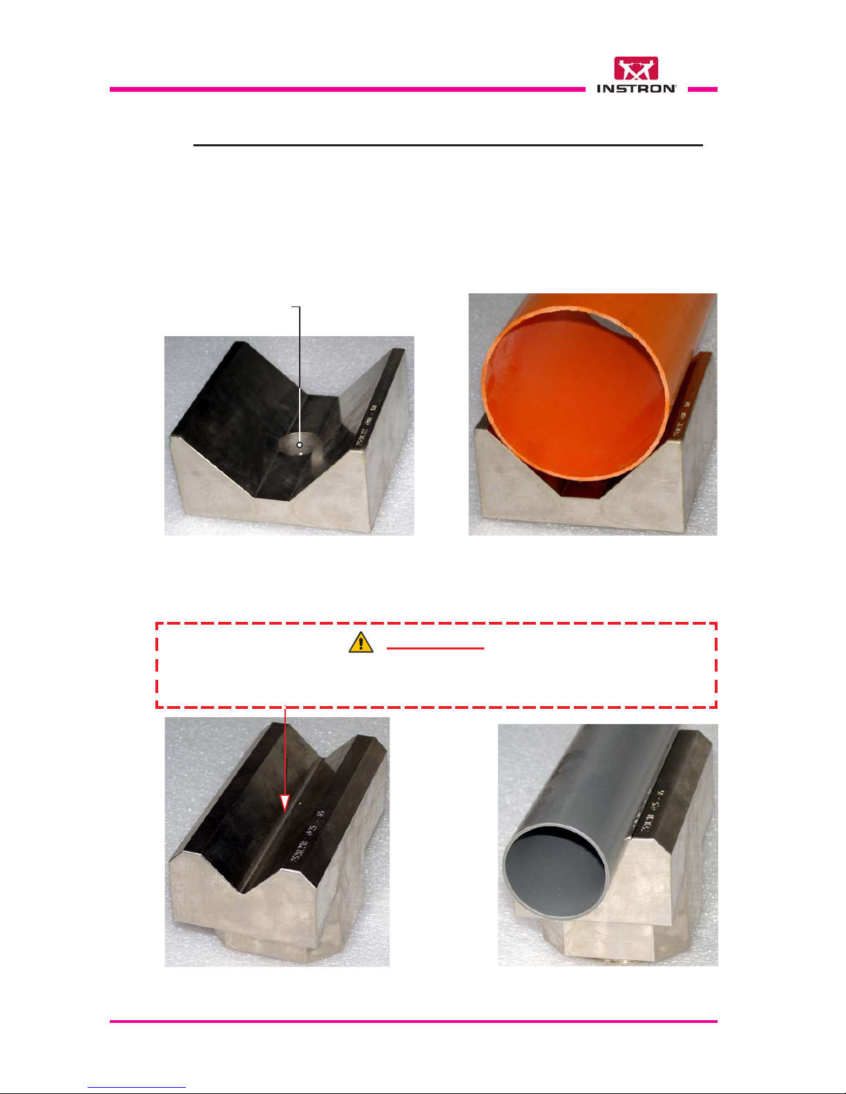
Page 100 - CEAST 9340 - Instructions for Use and Maintenance 7510.000MN1r ed. 1 rev . 1
8.9 SPECIAL-PURPOSE TOOLING FOR IMP ACT TESTS ON PIPES
This tooling allows to carry out impact tests on pipes of thermoplastic materials according
to the ASTM D-2444 standard.
8.9.1 INTRODUCTION
8.9.2 SUPPORTS
Fig. 1 - Pipe Support 90° code 7520.212 according to ASTM D-2444 standard for
pipes diameter 80 to160 mm (to be used together with the adjustable height support
code 7520.035)
Fig. 2 - Pipe Support 90° code 7520.210 according to ASTM D-2444 standard for
pipes diameter 25 to 65 mm (to be used together with the adjustable height support
code 7520.035)
Through hole for
striker passage
WARNING !
The support is unprovided of the through hole for the striker passage therefore avoid
the impact of the striker against the support surface during the tests.
 Loading...