

Page 1

5940 Series Single Column Table Frames
Operator’s guide M10-16245-EN Revision E
The difference is measurable
®
Page 2

Electromagnetic Compatibility
Where applicable, this equipment is designed to comply with International Electromagnetic Compatibility (EMC) standards.
To ensure reproduction of this EMC performance, connect this equipment to a low impedance
ground connection. Typical suitable connections are a ground spike or the steel frame of a building.
Proprietary Rights Notice
This document and the information that it contains are the property of Illinois Tool Works Inc.
(ITW). Rights to duplicate or otherwise copy this document and rights to disclose the document and
the information that it contains to others and the right to use the information contained therein may
be acquired only by written permission signed by a duly authorized officer of ITW.
Trademarks
Instron® is a registered trademark of Illinois Tool Wo rks Inc. (ITW). Other names, logos, icons and
marks identifying Instron products and services referenced herein are trademarks of ITW and may
not be used without the prior written permission of ITW.
Other product and company names used herein are trademarks or trade names of their respective
companies.
Original Instructions
© Copyright 2009 Illinois Tool Works Inc. All rights reserved. All of the specifications
shown in this document are subject to change without notice.
Worldwide Headquarters
Instron
825 University Avenue
Norwood, MA 02062-2643
United States of America
European Headquarters
Instron
Coronation Road
High Wycombe, Bucks HP12 3SY
United Kingdom
Industrial Products Group
Instron
900 Liberty Street
Grove City, PA 16127
United States of America
Page 3

General Safety Precautions
Materials testing systems are potentially hazardous.
Materials testing involves inherent hazards from high forces, rapid motions, and stored
energy . You must be aware of all moving and operating components in the testing system
that are potentially hazardous, particularly force actuators or a moving crosshead.
Carefully read all relevant manuals and observe all Warnings and Cautions. The term
Warning is used where a haza rd may lead to injury or death. The term Caution is used
where a hazard may lead to damage to equipment or to loss of data.
Instron products, to the best of its knowledge, comply with various national and
international safety standards, in as much as they apply to materials and structural
testing. We certify that our products comply with all relevant EU directives (CE mark).
Because of the wide range of applications with which our instruments are used, and over
which we have no control, additional protection devices and operating procedures may
be necessary due to specific accident prevention regulations, safety regulations, further
EEA directives or locally valid regulations. The extent of our delivery regarding
protective devices is defined in your initial sales quotation. We are thus free of liability
in this respect.
Preliminary Pages
At your request, we will gladly provide advice and quotations for additional safety
devices such as protective shielding, warning signs or methods of restricting access to
the equipment.
The following pages detail various general warnings that you must heed at all times
while using materials testing equipment. You will find more specific Warnings and
Cautions in the text whenever a potential hazard exists.
Your best safety precautions are to gain a thorough understanding of the equipment by
reading your instruction manuals and to always use good judgement.
It is our strong recommendation that you should carry out your own safety risk
assessment on the use of the test system, test methods employed, specimen loading and
specimen behavior at failure.
Product Support: www.instron.com
iii
Page 4
Preliminary Pages
Warnings
Crush Hazard - Allow only one person to handle or operate the system at all times.
Operator injury may result if more than one person operates the system. Before working
inside the hazard area between the grips or fixtures, ensure that no other personnel can
operate the computer or any of the system controls.
Crush Hazard - Take care when installing or removing a specimen, assembly,
structure, or load string component.
Installation or removal of a specimen, assembly, structure, or load string component
involves working inside the hazard area between the grips or fixtures. Keep clear of the
jaws of a grip or fixture at all times. Keep clear of the hazard area between the grips or
fixtures during actuator or crosshead movement. Ensure that all actuator or crosshead
movements necessary for installation or removal are slow and, where possible, at a low
force setting.
Hazard - Press the Emergency Stop button whenever you consider that an unsafe
condition exists.
The Emergency Stop button removes hydrau lic power or electrical dri ve from the testing
system and brings the hazardous elements of the system to a stop as quickly as possible.
It does not isolate the system from electrical power, other means are provided to
disconnect the electrical supply. Whenever you consider that safety may be
compromised, stop the test using the Emergency Stop button. Investigate and resolve the
situation that caused the use of the Emergency Stop button before you reset it.
Flying Debris Hazard - Make sure that test specimens are installed correctly in
grips or fixtures in order to eliminate stre sses that can cause breakage of grip
jaws or fixture components.
Incorrect installation of test specimens creates stresses in grip jaws or fixture components
that can result in breakage of these components. The high energies involved can cause
the broken parts to be projected forcefully some distance from the test area. Install
specimens in the center of the grip jaws in line with the load path. Insert specimens into
the jaws by at least the amount recommended in your g r ip documentation. This amount
can vary between 66% to 100% insertion depth; refer to supplied instructions for your
specific grips. Use any centering and alignment devices provided.
Hazard - Protect electrical cables from damage and inadvertent disconnection.
The loss of controlling and feedback signals that can result from a disconnected or
damaged cable causes an open loop condition that may drive the actuator or crosshead
rapidly to its extremes of motion. Protect all electrical cables, particularly transducer
cables, from damage. Never route cables across the floor without protection, nor suspend
cables overhead under excessive strain. Use padding to avoid chafing where cables are
routed around corners or through wall openings.
iv M10-16245-EN
Page 5

Preliminary Pages
Warnings
High/Low Temperature Hazard - Wear protective clothing when handling
equipment at extremes of temperature.
Materials testing is often carried out at non-ambient temperatures using ovens, furnaces
or cryogenic chambers. Extreme temperature means an operating temperature exceeding
60 °C (140 °F) or below 0 °C (32 °F). You must use protective clothing, such as gloves,
when handling equipment at these temperatures. Display a warning notice concerning
low or high temperature operation whenever temperature control equipment is in use.
You should note that the hazard from extreme temperature can extend beyond the
immediate area of the test.
Hazard - Do not place a testing system off-line from computer control withou t first
ensuring that no actuator or crosshead movement will occur upon transfer to
manual control.
The actuator or crosshead will immediately respond to manual control settings when the
system is placed off-line from computer control. Before transferring to manual control,
make sure that the control settings are such that unexpected actuator or crosshead
movement cannot occur.
Robotic Motion Hazard - Keep clear of the operating envelope of a robotic device
unless the device is de-activated.
The robot in an automated testing system presents a hazard because its movements are
hard to predict. The robot can go instantly from a waiting state to high speed operation in
several axes of motion. During system operation, keep away from the operating envelope
of the robot. De-activate the robot before entering the envelope for any purpose, such as
reloading the specimen magazine.
Hazard - Set the appropriate limits before performing loop tuning or running
waveforms or tests.
Operational limits are included within your testing system to suspend motion or shut off
the system when upper and/or lower bounds of actuator or crosshead travel, or force or
strain, are reached during testing. Correct setting of operational limits by the operator,
prior to testing, will reduce the risk of damage to test article and system and associated
hazard to the operator.
Electrical Hazard - Disconnect the electrical power supply before r emoving the
covers to electrical equipment.
Disconnect equipment from the electrical power supply before removing any electrical
safety covers or replacing fuses. Do not reconnect the power source while the covers are
removed. Refit covers as soon as possible.
Product Support: www.instron.com
v
Page 6
Preliminary Pages
Warnings
Rotating Machinery Hazard - Disc onnect power supplies before removing the
covers to rotating machinery.
Disconnect equipment from all power supplies before removing any cover which gives
access to rotating machinery. Do not reconnect any power supply while the covers are
removed unless you are specifically instructed to do so in the manual. If the equipment
needs to be operated to perform maintenance tasks with the covers removed, ensure that
all loose clothing, long hair, etc. is tied back. Refit covers as soon as possible.
Hazard - Shut down the hydraulic power supply and discharge hydraulic pres sur e
before disconnection of any hydraulic fluid coupling.
Do not disconnect any hydraulic coupling without first shutting down the hydraulic
power supply and discharging stored pressure to zero. Tie down or otherwise secure all
pressurized hoses to prevent movement during system operation and to prevent the hose
from whipping about in the event of a rupture.
Hazard - Shut off the supply of compressed gas and discharge residual gas
pressure before you disconnect any compressed gas coupling.
Do not release gas connections without first disconnecting the gas supply and
discharging any residual pressure to zero.
Explosion Hazard - Wear eye protection and use protective shields or screens
whenever any possibility exists of a hazard from the failure of a specimen,
assembly or structure under test.
Wear eye protection and use protective shields or screens whenever a risk of injury to
operators and observers exists from the failure of a test specimen, assembly or structure,
particularly where explosive disintegration may occur. Due to the wide range of
specimen materials, assemblies or structures that may be tested, any hazard resulting
from the failure of a test specimen, assembly or structure is entirely the responsibility of
the owner and the user of the equipment.
Hazard - Ensure components of the load string are correctly pre-loaded to
minimize the risk of fatigue failure.
Dynamic systems, especially where load reversals through zero are occurring, are at risk
of fatigue cracks developing if components of the load string are not correctly pre-loaded
to one another. Apply the specified torque to all load string fasteners and the correct
setting to wedge washers or spiral washers. Visually inspect highly stressed components
such as grips and threaded adapters prior to every fatigue test for signs of wear or fatigue
damage.
vi M10-16245-EN
Page 7

Preliminary Pages
Table of Contents
Chapter 1 Introduction . . . . . . . . . . . . . . . . . . . . . . . . . . . . . . . . . . . . . . . . . . . . . . . 1-1
System Description and Terminology. . . . . . . . . . . . . . . . . . . . . . . . . . . . . . . . . . . . 1-2
Components . . . . . . . . . . . . . . . . . . . . . . . . . . . . . . . . . . . . . . . . . . . . . . . . . . . 1-2
Principle of Operation. . . . . . . . . . . . . . . . . . . . . . . . . . . . . . . . . . . . . . . . . . . . 1-4
Hardware Controls . . . . . . . . . . . . . . . . . . . . . . . . . . . . . . . . . . . . . . . . . . . . . . 1-4
Software . . . . . . . . . . . . . . . . . . . . . . . . . . . . . . . . . . . . . . . . . . . . . . . . . . . . . . 1-4
System Components and Interconnections. . . . . . . . . . . . . . . . . . . . . . . . . . . . . . . 1-5
System Safety and Information Labeling. . . . . . . . . . . . . . . . . . . . . . . . . . . . . . . . . 1-6
Product Support. . . . . . . . . . . . . . . . . . . . . . . . . . . . . . . . . . . . . . . . . . . . . . . . . . . . 1-8
Product Documentation . . . . . . . . . . . . . . . . . . . . . . . . . . . . . . . . . . . . . . . . . . . . . . 1-8
Chapter 2 Preparing the System . . . . . . . . . . . . . . . . . . . . . . . . . . . . . . . . . . . . . . . 2-1
Before you Begin . . . . . . . . . . . . . . . . . . . . . . . . . . . . . . . . . . . . . . . . . . . . . . . . . . . 2-1
Power Input Connector. . . . . . . . . . . . . . . . . . . . . . . . . . . . . . . . . . . . . . . . . . . 2-1
Emergency Stop Button . . . . . . . . . . . . . . . . . . . . . . . . . . . . . . . . . . . . . . . . . . 2-2
Start the System. . . . . . . . . . . . . . . . . . . . . . . . . . . . . . . . . . . . . . . . . . . . . . . . . . . . 2-2
Control Panel. . . . . . . . . . . . . . . . . . . . . . . . . . . . . . . . . . . . . . . . . . . . . . . . . . . . . . 2-3
Bluehill Software . . . . . . . . . . . . . . . . . . . . . . . . . . . . . . . . . . . . . . . . . . . . . . . . . . . 2-6
Home Screen . . . . . . . . . . . . . . . . . . . . . . . . . . . . . . . . . . . . . . . . . . . . . . . . . . 2-6
Console. . . . . . . . . . . . . . . . . . . . . . . . . . . . . . . . . . . . . . . . . . . . . . . . . . . . . . . 2-6
Status Bar. . . . . . . . . . . . . . . . . . . . . . . . . . . . . . . . . . . . . . . . . . . . . . . . . . . . . 2-7
Assemble the Load String . . . . . . . . . . . . . . . . . . . . . . . . . . . . . . . . . . . . . . . . . . . . 2-8
Select a Load Cell. . . . . . . . . . . . . . . . . . . . . . . . . . . . . . . . . . . . . . . . . . . . . . . 2-8
Install the Load Cell . . . . . . . . . . . . . . . . . . . . . . . . . . . . . . . . . . . . . . . . . . . . . 2-9
Adapters . . . . . . . . . . . . . . . . . . . . . . . . . . . . . . . . . . . . . . . . . . . . . . . . . . . . . 2-11
Select Grips and Fixtures . . . . . . . . . . . . . . . . . . . . . . . . . . . . . . . . . . . . . . . . 2-14
Insert Jaw Faces into Grips . . . . . . . . . . . . . . . . . . . . . . . . . . . . . . . . . . . . . . 2-15
Install Grips . . . . . . . . . . . . . . . . . . . . . . . . . . . . . . . . . . . . . . . . . . . . . . . . . . . . . . 2-15
Preload the Load String. . . . . . . . . . . . . . . . . . . . . . . . . . . . . . . . . . . . . . . . . . . . . 2-17
To preload the load string: . . . . . . . . . . . . . . . . . . . . . . . . . . . . . . . . . . . . . . . 2-17
To unload the load string: . . . . . . . . . . . . . . . . . . . . . . . . . . . . . . . . . . . . . . . . 2-18
Product Support: www.instron.com
vii
Page 8

Preliminary Pages
Chapter 3 Testing Specimens . . . . . . . . . . . . . . . . . . . . . . . . . . . . . . . . . . . . . . . . . 3-1
Testing a Sample . . . . . . . . . . . . . . . . . . . . . . . . . . . . . . . . . . . . . . . . . . . . . . . . . . . 3-2
Create a sample in Bluehill . . . . . . . . . . . . . . . . . . . . . . . . . . . . . . . . . . . . . . . . . . . 3-4
Create a new sample . . . . . . . . . . . . . . . . . . . . . . . . . . . . . . . . . . . . . . . . . . . . 3-4
Name the new sample . . . . . . . . . . . . . . . . . . . . . . . . . . . . . . . . . . . . . . . . . . . 3-5
Calibrate a transducer . . . . . . . . . . . . . . . . . . . . . . . . . . . . . . . . . . . . . . . . . . . . . . . 3-6
Automatic calibration . . . . . . . . . . . . . . . . . . . . . . . . . . . . . . . . . . . . . . . . . . . . 3-6
Manual calibration. . . . . . . . . . . . . . . . . . . . . . . . . . . . . . . . . . . . . . . . . . . . . . . 3-7
Set the zero extension point . . . . . . . . . . . . . . . . . . . . . . . . . . . . . . . . . . . . . . . . . . 3-9
From Bluehill software . . . . . . . . . . . . . . . . . . . . . . . . . . . . . . . . . . . . . . . . . . . 3-9
From the Control Panel. . . . . . . . . . . . . . . . . . . . . . . . . . . . . . . . . . . . . . . . . . . 3-9
Set the crosshead limit stops. . . . . . . . . . . . . . . . . . . . . . . . . . . . . . . . . . . . . . . . . 3-10
Set the crosshead limit stops:. . . . . . . . . . . . . . . . . . . . . . . . . . . . . . . . . . . . . 3-10
Move Off a Crosshead Limit Stop . . . . . . . . . . . . . . . . . . . . . . . . . . . . . . . . . . 3-11
Set the limits for a transducer . . . . . . . . . . . . . . . . . . . . . . . . . . . . . . . . . . . . . . . . 3-12
Balance a transducer. . . . . . . . . . . . . . . . . . . . . . . . . . . . . . . . . . . . . . . . . . . . . . . 3-12
Stop a test . . . . . . . . . . . . . . . . . . . . . . . . . . . . . . . . . . . . . . . . . . . . . . . . . . . . . . . 3-13
Control Panel Buttons. . . . . . . . . . . . . . . . . . . . . . . . . . . . . . . . . . . . . . . . . . . 3-13
Emergency Stop Button . . . . . . . . . . . . . . . . . . . . . . . . . . . . . . . . . . . . . . . . . 3-13
Crosshead Limit Switches . . . . . . . . . . . . . . . . . . . . . . . . . . . . . . . . . . . . . . . 3-14
Software Controls. . . . . . . . . . . . . . . . . . . . . . . . . . . . . . . . . . . . . . . . . . . . . . 3-14
Shut down the system . . . . . . . . . . . . . . . . . . . . . . . . . . . . . . . . . . . . . . . . . . . . . . 3-14
Troubleshooting. . . . . . . . . . . . . . . . . . . . . . . . . . . . . . . . . . . . . . . . . . . . . . . . . . . 3-15
A Software Transducer Limit Trips . . . . . . . . . . . . . . . . . . . . . . . . . . . . . . . . . 3-15
A Crosshead Travel Limit Trips. . . . . . . . . . . . . . . . . . . . . . . . . . . . . . . . . . . . 3-16
You press the Emergency Stop button . . . . . . . . . . . . . . . . . . . . . . . . . . . . . . 3-16
The System Shuts down Unexpectedly . . . . . . . . . . . . . . . . . . . . . . . . . . . . . 3-16
Appendix A Conformance Documents. . . . . . . . . . . . . . . . . . . . . . . . . . . . . . . . . . . . A-1
Certificate of Conformance . . . . . . . . . . . . . . . . . . . . . . . . . . . . . . . . . . . . . . . . . . . A-2
viii M10-16245-EN
Page 9

Chapter 1
Introduction
• System Description and Terminology . . . . . . . . . . . . . . . . . . . . . . . . . . . . . . . . . . . 1-2
• System Components and Interconnections. . . . . . . . . . . . . . . . . . . . . . . . . . . . . . . . 1-5
• System Safety and Information Labeling. . . . . . . . . . . . . . . . . . . . . . . . . . . . . . . . . 1-6
• Product Support . . . . . . . . . . . . . . . . . . . . . . . . . . . . . . . . . . . . . . . . . . . . . . . . . . . . 1-8
• Product Documentation . . . . . . . . . . . . . . . . . . . . . . . . . . . . . . . . . . . . . . . . . . . . . . 1-8
These instructions describe the following table model single column load frames, Model
5942 500 N capacity, Model 5943 1 kN capacity, Model 5944 2kN capacity. They are
intended to get you started working with your testing system.
These instructions assume the following:
• You are an operator familiar with the operation of materials testing systems in general.
• Your system consists of a load frame with integral controller and a control panel fitted to
®
the column, a load cell, a set of manually-operated grips and Instron Bluehill
control software.
test
• The system has been installed in its final location by an Instron service engineer.
• Bluehill software test methods that are appropriate for your testing requirements are
available.
Using these instructions you will be able to:
• Check the interconnections between all the individual elements of the basic system.
• Select and install a load cell, if the one that you want to use is not already installed.
• Install the grips and preload the loadstring.
• Prepare a set of specimens (sample) for testing.
• Test the sample.
• View the test results and print a test report.
These instructions do not include the development of Bluehill test methods. This is covered
in more advanced training that can be provided by Instron Service and Training
departments.
1-1
Page 10

Chapter: Introduction
Frame base
Base
Base adapter
Controller
Motor cover
Ground stud
Not shown: Computer
T-slots
Crosshead
Lifting eye
Emergency stop
button
Power input
connector
Control
panel
beam
System ID label
Options
panel
Upper limit stop
Lower limit stop
Ballscrew cover
Column
cover
System Description and Terminology
Components
The major components of an Instron electromechanical testing system include:
Figure 1-1. 5940 Single Column Table Frame
• Load frame with integral controller
• Load cell mounted to the crosshead
1-2 M10-16245-EN
Page 11

System Description and Terminology
• Grips for tension testing or table-mounted anvils on a platen for compression testing.
• Instron approved computer system with Instron Bluehill
Special fixtures are available for applications such as flexure and peel testing. For strain
measurement, an optional strain gauge extensometer attaches to the specimen. You can use
non-contacting extensometers with specimens that are unable to support a contacting
extensometer. Contact your regional Instron office or check our web site at
www.instron.com
The following table defines the components of the testing system:
Component Description
Load Frame The load frame comprises a base, one or two columns, a moving
for assistance with Instron’s grips and fixtures.
Table 1-1. Testing System Components
crosshead, and a top plate. It is a high stiffness support structure
against which the test forces react.
Each column comprises a guide column and a ballscrew. The
crosshead is mounted on both the guide column and the ballscrew.
Rotation of the ballscrew drives the crosshead up or down while the
guide column provides stability.
®
software.
Controller The hardware that controls the frame and any ancillary equipment
connected to the testing system. The controller panel contains all the
connectors for load cells, extensometers and any other sensors that
are required for testing.
Control Panel The hardware panel, mounted on the side of the load frame, that lets
you perform some of the software functions directly at the frame.
Load String Comprises all of the components that you install between the moving
crosshead and the load frame base (or fixed crosshead). Typically
this involves a load cell, a set of grips, any adapters that are required
to connect the components, and the specimen to be tested.
Typically, you mount a load cell on the crosshead, then a pair of grips
or fixtures on the load cell and frame base. The grips or fixtures
secure the specimen and when you start a test the crosshead moves
up or down applying a tensile or compressive load to the specimen.
The load cell converts this load into an electrical signal that the
software measures and displays.
Bluehill Software Instron testing software that controls the testing system, running tests
and analyzing test data to produce test results.
Specimen A single piece of material to be tested.
Product Support: www.instron.com
1-3
Page 12

Chapter: Introduction
Principle of Operation
The system communicates primarily through the controller. The controller contains sensor
conditioning cards for the system transducers and transfers data between the transducers and
the computer. The controller also communicates with the load frame via a frame interface
board (FIB) inside the load frame. The FIB links all the electrical components of the frame
together.
Hardware Controls
The hardware controls consist of:
• Emergency stop button - to be used whenever you need to stop the crosshead
immediately because an unsafe condition exists.
• Limit stops - these must be set before each test session to protect the operator against
unexpected crosshead movement.
• Control panel - lets you perform certain functions at the frame instead of at the
computer. These include starting and stopping a test and using the jog controls to
position the crosshead prior to installing a specimen.
Software
Control of the testing system is carried out via Instron Bluehill software. Setting test
parameters, operating the system, and collecting test data is done through the software
program.
Table 1-2. Software Terminology
Term Description
Test Method In Bluehill software, a test method is a file that contains a set of
defined parameters that the system uses to run tests, analyze the test
data, and produce calculated results.
Sample A group of material specimens, whose properties are studied and
compared to gain statistical or quality assurance information. For
example, you could take a specimen from different parts of a single
manufacturing run of a material to form a sample of the material. The
sample is then representative of the complete run and you can test it
to ensure that the material quality has remained stable over the
complete run. You perform the same test on each specimen in a
sample.
1-4 M10-16245-EN
Page 13

System Components and Interconne ctions
Load cell
Load cell
cable
Mains power cable
Ground stud
Computer interface
Ethernet crossover
cable
connection
Computer interface
connection
Controller cover
Load cell connector
Controller
Supplemental ground cable
GRN/YEL - Earth
BRN - Live
BLU - Neutral
System ID label
Options panel
System Components and Interconnections
Figure 1-2 on page 1-5 shows you how each hardware component is connected to make up
the complete testing system.
Figure 1-2. 5940 System Connections
Product Support: www.instron.com
1-5
Page 14

Chapter: Introduction
System Safety and Information Labeling
Table 1-3 on page 1-6 explains the meanings of any safety and information labels that may
be attached to any part of the testing system.
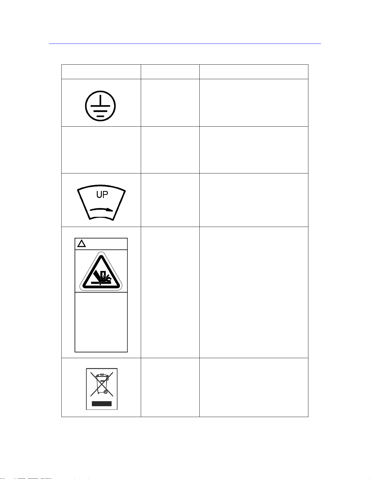
Table 1-3. Safety and Information Labeling Descriptions
Label Meaning Purpose
Electrical
hazard
Disconnect power
supply
Electrical - fuse
warning Indicates an electrical hazard exists.
Belt
entanglement hazard
Indicates that an electrical hazard exists
from high voltage or electrical current.
Disconnect the power supply before
servicing machine.
Advises about disconnecting power mains
before changing fuses and using only
specified fuses.
Indicates that a hazard exists from the
drive belt and pulley system.
High
temperature hazard
Rotating machinery
hazard
Indicates that a heat hazard exists. Stay
clear of area when operating the machine.
Indicates that a rotating hazard exists.
Keep clear of these areas (and tie back
long hair).
1-6 M10-16245-EN
Page 15
System Safety and Information Labeling
Crush hazard.
Keep clear of test
area when machine
is in motion.
Read and understand
operator's manual
before using this
machine.
!
WARNING
Table 1-3. Safety and Information Labeling Descriptions (Continued)
Label Meaning Purpose
Ground stud Indicates a ground stud.
Read the manual Read and understand the operator’s
manual before using the machine.
Crosshead direction Indicates the direction to turn the pulley to
manually move the crosshead upward.
Pulleys can be turned by hand when
power is disabled.
Crush hazard Indicates the crush hazard of the moving
crosshead and instructs the user to read
and understand the operator’s manual
before using the machine.
Waste Electrical and
Electronic Equipment
(WEEE)
In accordance with the European Union’s
WEEE directive, the crossed out wheeled
bin symbol indicates that the equipment
must be disposed of separately from other
waste at the end of its usable life. For
advice on the disposal of electrical and
electronic equipment in your country,
contact your local Instron representative.
Product Support: www.instron.com
1-7
Page 16

Chapter: Introduction
Product Support
Instron provides documentation, including manuals and online help, that can answer many
of the questions you may have. It is recommended that you review the documentation sent
with the system you purchased for possible solutions to your questions.
If you cannot find answers in these sources, contact Instron’s Service department directly . A
list of Instron offices is available on our website at www.instron.com. In the US and
Canada, you can call directly at 1-800-473-7838.
Product Documentation
Instron offers a comprehensive range of documentation to help you get the most out of your
Instron products. Depending on what you have purchased, your documentation may include
some or all of the following:
Operator’s Guide How to use your system components and controls,
procedures for setting limits, calibration and other
frequently performed operating tasks.
System Support Information about system installation, set up and
configuration, transducer connection and calibration.
Online Help Software products come complete with context
sensitive help, which provides detailed information on
how to use all software features.
Accessory
Equipment Reference
We welcome your feedback on any aspect of the product documentation. Please email
info_dev@instron.com with your comments.
How to set up and use any accessories you have
purchased, for example grips, fixtures, extensometers,
transducers, and environmental chambers.
1-8 M10-16245-EN
Page 17
• Before you Begin . . . . . . . . . . . . . . . . . . . . . . . . . . . . . . . . . . . . . . . . . . . . . . . . . . . 2-1
• Start the System . . . . . . . . . . . . . . . . . . . . . . . . . . . . . . . . . . . . . . . . . . . . . . . . . . . . 2-2
• Control Panel . . . . . . . . . . . . . . . . . . . . . . . . . . . . . . . . . . . . . . . . . . . . . . . . . . . . . . 2-3
• Bluehill Software . . . . . . . . . . . . . . . . . . . . . . . . . . . . . . . . . . . . . . . . . . . . . . . . . . . 2-6
• Assemble the Load String . . . . . . . . . . . . . . . . . . . . . . . . . . . . . . . . . . . . . . . . . . . . 2-8
• Preload the Load String . . . . . . . . . . . . . . . . . . . . . . . . . . . . . . . . . . . . . . . . . . . . . 2-17
Before you Begin
Before you start the system, make sure you familiarize yourself with the following controls:
Chapter 2
Preparing the System
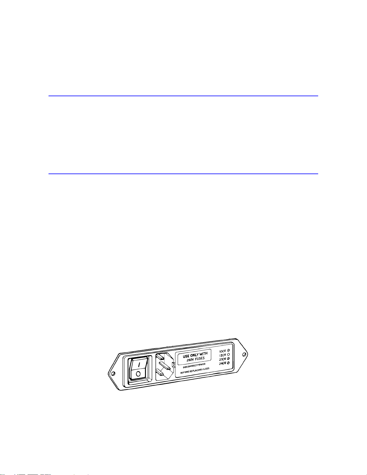
Power Input Connector
The power input connector, shown in Figure 2-1, performs the following functions:
• Connects the load frame to the electrical power supply.
• Contains the power ON/OFF switch.
• Holds the power fuse.
• Controls the voltage setting. The voltage setting can be changed if necessary , refer to the
System Support manual for details.
Figure 2-1. Power Input Connector
2-1
Page 18
Chapter: Preparing the System
Refer to Figure 1-1 on page 1-2 to see the location of the power input connector on the
load frame.
Emergency Stop Button
Figure 2-2. Emergency Stop Button
The Emergency Stop button is a large, round, red button on the testing system. Press this
button to stop the test as soon as possible when a condition develops that:
• Could affect the safety of persons operating the system.
• Could damage the specimen, load frame, or test fixtures.
Start the System
Before operating the system each day, ensure:
• All cables are properly installed and securely connected.
• All cables are free of wear and chafing. Re-route the cables if necessary, and replace any
damaged cables.
• Signal and power cables have adequate slack to prevent excessive strain on connectors.
• All grips, fixtures and accessories are free of dirt, damage and deformation.
• The load frame is level. If an adjustment is necessary, refer to the System Support
manual.
Correct any problems before you operate the testing system. If you require assistance,
contact your local Instron Service department.
2-2 M10-16245-EN
Page 19

Control Panel
Warning
1. Turn the power switch for the frame to the On (I) position. Ensure that the POWER
indicator light illuminates.
2. Power on all other system components (e.g. computer and any other accessories).
3. Observe the display on the control panel; an hourglass displays while the system
performs its self-test procedure. The procedure is complete when the hourglass
disappears and only the Instron logo displays.
If the hourglass persists or if it is replaced with a warning icon, then the self-test has not
been successful. Contact Instron Service.
4. When the system self-test has completed successfully, start the Instron Bluehill
software.
5. Wait for the software to fully initialize the machine before using the jog controls on the
machine. The machine relay makes a clicking sound before the machine is ready.
6. Ensure that the
Refer to “Control Panel” on page 2-3 and “Bluehill Software” on page 2-6. for details
of the controls available in each.
Control Panel
The control panel attaches to one of the column covers on the load frame and works in
conjunction with the software to operate the frame. The control panel lets you perform many
of the software functions directly at the frame, so you can perform these functions either at
the computer or at the load frame.
Crush Hazard - Do not place your hands between the moving grips or fixtures
while operating any controls on the control panel.
FRAME READY indicator on the control panel illuminates.
The display and its associated numbered buttons operate together with Bluehill software.
Any soft key functions that you have assigned in Bluehill are shown in the display next to
the appropriate button. Pressing a button performs the action displayed next to it.
Use the toggle button on the left of the display key to toggle the display between soft key
functions and up to 4 live displays. The live displays are copies of any live displays that you
If the display is showing live displays you must toggle back to show the softkey functions if
you want to use a soft key button on the control panel.
Product Support: www.instron.com
2-3
Page 20

Chapter: Preparing the System
Figure 2-3. Control Panel
2-4 M10-16245-EN
Page 21

Control Panel
Table 2-1. Control Panel Functions
Control Function
JOG UP Press the JOG UP arrow button to move the crosshead in tension (away from the
base beam). Pressing the button increases the speed linearly, up to a maximum speed,
until you release the button.
JOG DOWN Press the JOG DOWN arrow button to move the crosshead in compression
(toward the base beam). Pressing the button increases the speed linearly, up to a
maximum speed, until you release the button.
FINE JOG Turn this thumbwheel to slowly position the crosshead. This control lets you set an
accurate zero extension point, or set a precise grip position for loading specimens.
Note: on some control panels, this control is labeled
FINE POSITION.
ZERO
EXTENSION
Press this button to set the current position of the crosshead as the zero extension point
(or gauge length) position. After setting the zero extension point, the crosshead returns
to this position when:
• You press the RETURN button
• The crosshead encounters a pre-set limit or event that instructs the crossh ead to
return to the zero extension point
Note’: on some control panels, this button is labeled
RESET GL (reset gauge length).
AT Z E RO This indicator illuminates when the crosshead is at the zero extension point.
Note’: on some control panels, this indicator is labeled
AT GL (at gauge length).
POWER This indicator illuminates when the system power is in either STANDBY or FRAME
SPECIMEN
PROTECT
READY
its conditioner board but not to the frame. In FRAME READY mode, the system
supplies power to all load frame and transducer components. This indicates that the test
system is ready for operation.
Press this button to toggle on or off the SPECIMEN PROTECT function. This
function protects the test specimen and load string components from overloads.
The
mode. In STANDBY mode, the system supplies power to the load cell and
ON indicator flashes when SPECIMEN PROTE CT is functioning.
START TEST After you set the test parameters, press this button to begin the test. When the
crosshead starts to move, the appropriate
illuminates showing the direction of crosshead movement.
TEST IN PROGRESS indicator
STOP TEST Press this button to stop crosshead motion during or at the end of a test. The TEST
STOPPED
crosshead has not returned to the gauge length position.
indicator illuminates to show that the test has stopped, but that the
RETURN Press this button to move the crosshead back to the gauge length position after a test.
RETURN IN PROGRESS indicator illuminates to show that the crosshead is
The
returning to the gauge length position.
Figure 2-3 on page 2-4 illustrates the control panel. Table 2-1 on page 2-5 describes the
control panel’s functions.
Product Support: www.instron.com
2-5
Page 22

Chapter: Preparing the System
Bluehill Software
Setting test parameters, operating the system, and collecting test data is done through the
software program.
Home Screen
Bluehill software opens at the Home screen. The console section of the software is at the
top of the screen and provides important information about the system. The console is
always visible and always available from any screen within the software.
Buttons on the Home screen take you to other parts of the software, as follows:
Button Function
Test Click this button to perform tests on specimens. The software displays a
sequence of screens where you:
1. choose a test method from which to load test parameters.
2. name the sample and select a location to store the test data.
3. perform tests.
Table 2-2. Buttons on the Home screen
Console
Method Click this button to edit and save test method files.
Refer to the software online help.
Analysis Click this button to either modify an existing sample or replay a sample with
parameters from a different test method.
Refer to the software online help.
Admin Click this button to change the configuration of the testing system.
Refer to the software online help.
User This button is grayed if Security is not enabled.
Click this button to log out the current user and let a new user log in to the
software. When you log out you do not exit the program.
Help Click this button to open the online help.
Exit Click this button to exit the program.
The console area of the software provides important information during testing and is also
where you can edit system wide settings.
2-6 M10-16245-EN
Page 23

Table 2-3. Console Controls
Control Function
Bluehill Software
Frame status
indicator
System settings This area contains a number of buttons, one for each component that makes
Soft keys You can assign up to four functions that you use frequently to these keys. Each
Live display You can set up a number of live displays that display values of parameters that
During test setup, the image of the frame changes according to the status of
the testing system.
• image grayed when frame is disabled
• green arrow superimposed on image indicates direction that crosshead
will move when test starts
When a test is running, the image changes to display the icon of the transducer
that is controlling the test. A large green arrow flashes to indicate the direction
of the test and that the test is running.
up the testing system, as follows:
• Frame - enables and disables the frame and set the jog speed
• Extension - lets you set limits for extension and reset the gauge length
• Load - lets you set limits for load, calibrate and balance the load cell
• Strain - lets you set limits for strain, calibrate and balance the
extensometer connected to this channel
Other buttons will display for other more specialized equipment, for example a
video extensometer or automatic extensometer.
key can display on the control panel so that you can perform that function from
the software console or from the control panel. Examples of common functions
assigned to soft keys are Balance Load and Reset Gauge Length.
you choose throughout the test.
System event log The event log provides information and warnings regarding various aspects of
the system. These include frame status messages, indications that certain test
method parameters are preventing the start of a test, or indications that the
system cannot open a sample file or method file.
Status Bar
The status bar appears at the bottom of every screen and provides status information for:
• Security - is security enabled and, if it is, the name of the current user.
• Machine - is the software connected to a testing machine or running in demo mode.
• Sample - the name of the current sample.
• Method - the name of the current method file that is open, if any.
• Report - the name of the current report template that is open.
Product Support: www.instron.com
2-7
Page 24

Chapter: Preparing the System
• Progress messages - various messages indicating progress, for example “Opening”,
“Closing” and “Generating”.
Assemble the Load String
The load string consists of all the hardware components between the crosshead and the base
of the testing machine. It includes the load cell, the grips, the specimen and any adapters that
allow you to connect all of these components together.
The service engineer will set up the testing machine during the installation, but you may
need to change one or more of these components for different types of testing.
When creating a load string, keep in mind the maximum capacity for all the components
making up the load string. The expected test load should not exceed the maximum cap a city
of any load string component including, but not limited to:
• load frame
• load cell
• adapters
• grips or fixtures
Select a Load Cell
If you know the approximate tensile or compressive strength of the material that you are
testing, use these guidelines to choose a load cell:
• The minimum test load must be greater than the smallest load cell capacity range shown
in the specifications for your machine.
• If there is a choice between two different load cells because of overlapping ranges:
• select a higher capacity load cell when you require minimum deflection
• select a lower capacity load cell when you require maximum long term balance or
stability
If you don’t know the tensile strength of the material, refer to a Properties of Materials
handbook to obtain an approximate strength. To calculate the tensile strength in force units
for a specimen, use the following equation:
tensile strength x cross-sectional area
2-8 M10-16245-EN
Page 25

Assemble the Load String
For example, for a standard ASTM tensile specimen (0.502 in wide, 0.125 in thick) made
with a material of tensile strength 5200 psi (from Materials Handbook) perform the
following calculation:
5200 x 0.502 x 0.125 = 328 lbf
This produces a recommendation of the 5 kN (1000 lb, 500kg) capacity load cell.
If you cannot determine an approximate value of tensile strength, use the highest capacity
load cell rated for the frame. Perform a preliminary test at a very slow speed to obtain the
load range required. You can then determine if a lower capacity load cell can provide
improved resolution.
Table 2-4 on page 2-9 lists the load cells that are recommended for use with 5940 Series
frames. If you have a load cell that is not listed, contact Instron for advice on compatibility
and adapters that may be available for your load cell.
Table 2-4. Compatible Load Cells for 5940 Frames
Torque - load cell to machine - Nm (ft-lb) 19 (14)
Install the Load Cell
Check the following before installing a load cell:
The load cell installation drawings are available and you have all the parts that are
required for the installation.
Capacity
Load Cell
Catalog no. 2580-105 2580-106 2580-107
Weight - kg (lb) 0.6 (1.3)
Effective Length - mm (in) 100 (3.9)
Machine Interface M10 x 40 long x 1.5 pitch
Accessory Interface Integral type O (female)
500 N 1 kN 2 kN
RH central thread
12 mm clevis with 6 mm clevis pin
Mounting screws are lubricated.
A torque wrench is available.
All threads, bores and mating surfaces are clean and free of damage.
Product Support: www.instron.com
2-9
Page 26

Chapter: Preparing the System
A
B
C
D
Load cell
Crosshead
The crosshead is positioned below its travel midpoint so that you can easily and safely
access the crosshead.
The crosshead is stationary and the TEST IN PROGRESS indicator light is not
illuminated.
Refer to Figure 2-4 on page 2-10 and perform the following procedure.
Figure 2-4. Installing the Load Cell
Load cell installation procedure:
1. Refer to the load cell installation drawing and collect together the correct mounting
screw , washer, anti-rotation pin and locating ring for your combination of load frame
and load cell.
2-10 M10-16245-EN
Page 27

Assemble the Load String
Caution
2. Assemble the mounting screw (A) and washer (B), as shown in the figure.
3. Place the mounting screw and washer assembly into the top of the central bore of the
crosshead.
4. Insert the anti-rotation pin (C) into one of the holes on the bottom of the crosshead.
There are four pin holes on the bottom of the crosshead that let you position the load cell
either straight on or at a 45° angle.
5. Place the locating ring (D) into the top of the load cell that connects to the crosshead.
6. Place the load cell against the bottom of the crosshead, ensuring that the anti-rotation
pin and locating ring fit securely in place against both the crosshead and load cell. Place
the cable to the left side of the column.
7. Tighten the mounting screw by hand so that it secures to the load cell underneath the
crosshead.
When applying torque to the mounting screw, prevent the load frame from sliding by
holding the crosshead with one hand while applying torque with the other.
8. Set the torque wrench to the value specified in the load cell installation drawing (and in
“Compatible Load Cells for 5940 Frames” on page 2-9) and tighten the mounting
screw .
9. Connect the load cell cable to the
connector is fully engaged in the socket.
10. Press the load cell cable into the clips on the rear of the column cover to prevent it from
interfering with your test.
11. Calibrate the load cell (refer to “Calibrate a transducer” on page 3-6).
12. Leave the system on for at least 15 minutes to allow the load cell circuitry to stabilize.
After this warm-up period, calibrate the load cell again.
Adapters
Adapters let you connect grips or fixtures to the frame when the interfaces have different
connection sizes. There are two types of adapters: base adapters and coupling adapters.
Base Adapters
LOAD connector on the controller. Ensure that the
Base adapters let you connect grips and fixtures to the base of the load frame. All 5940
Series load frames are supplied with a Type O base adapter installed. A T ype D base adapter
Product Support: www.instron.com
2-11
Page 28
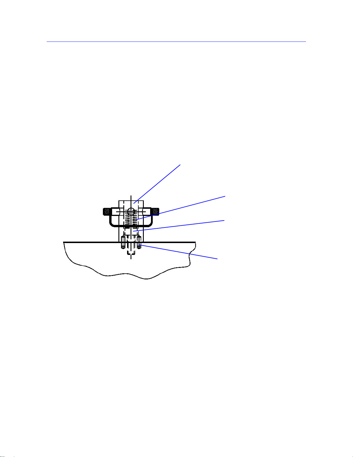
Chapter: Preparing the System
Locating pins
Base adapter
M6 bolt
Compression spring
is also supplied in the ancillary parts kit. If you need to remove and re-install the base
adapter, for example to change the orientation, use one of the following procedures.
To remove the base adapter:
1. Remove the compression spring located inside the adapter.
2. Insert a 5mm hex key into the base adapter, ensuring that it fits into the screw at the base
of the adapter.
3. Using a torque wrench, loosen and remove the screw inside the adapter.
4. Lift the base adapter away from the base beam.
Figure 2-5. Type O Base Adapter
To re-install the base adapter:
1. Insert the adapter into the base beam, noting the orientation of the locating pin on the
bottom of the adapter . The locating pin fits into any of the three locating pin holes on the
base beam.
2. Insert a 5mm hex key into the base adapter, ensuring that it fits into the screw at the base
of the adapter.
3. Using a torque wrench, tighten the screw to 7 Nm (5.2 ftlb)
4. Remove the hex key and insert the compression spring.
2-12 M10-16245-EN
Page 29
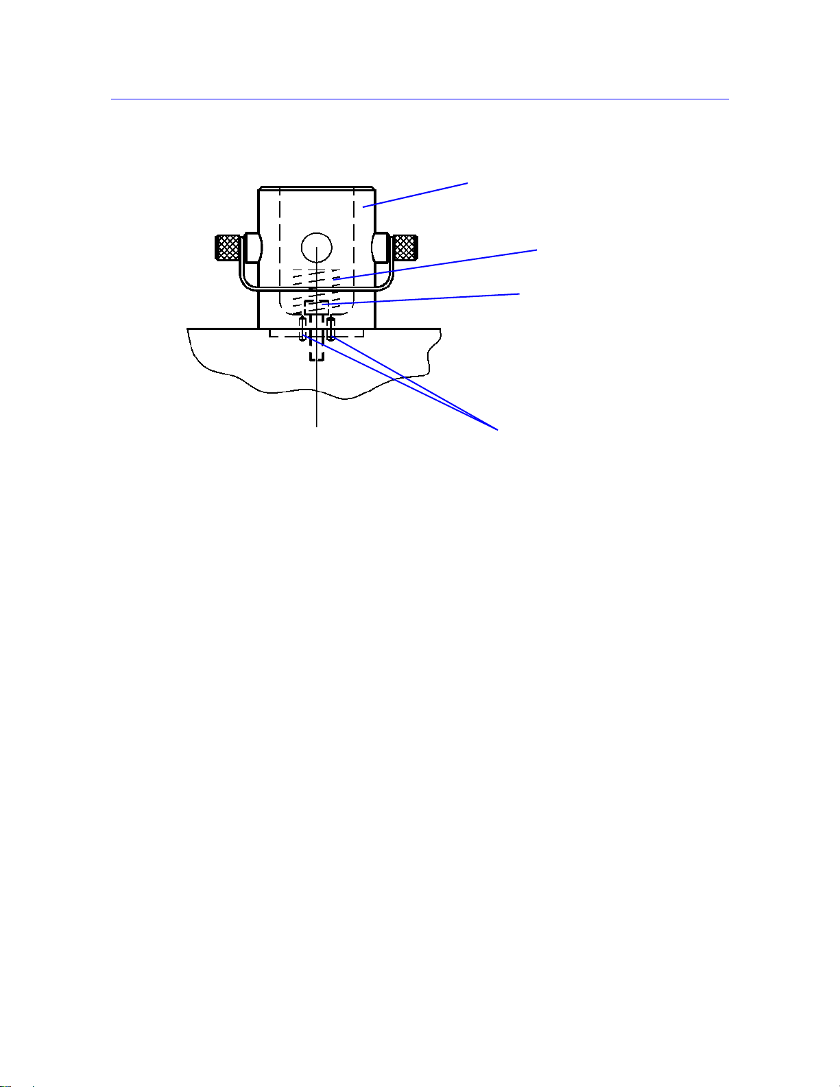
Figure 2-6. Type D Base Adapter
Base adapter
Compression
spring
M6 bolt
Locating pins
Assemble the Load String
Product Support: www.instron.com
2-13
Page 30

Chapter: Preparing the System
Coupling Adapters
Coupling adapters let you attach grips and fixtures of different sizes to the load cell and base
adapter, providing more options for testing. There are two primary types:
• For tension testing only:
Tension coupling adapters, also known as self-aligning coupling adapters, which
provide a swivel connection and connect between clevis pin type interfaces. The swivel
action allows the grip or fixture to self-align in the direction of the test load, thus
minimizing any bending load on the specimen.
• For tension or compression testing:
Rigid coupling adapters which also connect between clevis pin type interfaces but use
checknuts to provide fixed connections. This type can also have a threaded interface.
These couplings are not self-aligning and the load string alignment is dependent on the
accuracy of load cell alignment during installation.
When assembling the load string, you may need to use adapters if the load cell interface, or
base adapter interface, differs from your grip interface. A coupling adapter creates a secure
connection between these two different interfaces.
If your grip or fixture interface is the same size as your load cell interface, then you can
connect these directly and you do not need an adapter. If, however, you need the selfaligning feature that the adapter offers, you should use the appropriate self-aligning coupling
adapter.
Coupling types are listed from the load cell towards the accessory or from the frame base
towards the accessory. For example, if you need to connect a load cell with a Type D
(female) connector to a grip with a Type O (male) connector you require a Type Dm to Of
adapter.
Select Grips and Fixtures
A set of grips are installed on the system during installation by a service engineer. If your
testing requires it, you may need to install a different set to obtain optimum test results.
The selection of grips depends on the material, geometry and strength of the test specimen.
In compression testing, the diameter or area of the anvil is important, in addition to the
maximum loading capacity .
For tensile testing:
Make sure the tensile strength of the specimen does not exceed the maximum loading
capacity of the grips.
Minimize the risk of slippage by:
2-14 M10-16245-EN
Page 31

selecting jaw faces with a surface area large enough to cover the tab (for dumbbell-
•
shaped specimens) or as much surface area as possible for parallel-sided specimens.
• ensuring that the specimen is gripped by at least 75% of the available jaw face
length.
• using serrated jaw faces
Breaks at the jaw face may be caused by:
• Screw action grips - you may be using too much force when tightening the grips.
Use a torque wrench or switch to pneumatic grips for a consistent force.
• Pneumatic grips - the pressure may be too high. Drop the pressure, but not to the
point where you get slippage.
• Serrated faces - the serrations are damaging the specimen. Change to faces that have
more serrations per inch (less bite) or cover with masking tape or similar material to
soften the bite and prevent damage to the specimen.
Insert Jaw Faces into Grips
Install Grips
Different grips use different mechanisms for attaching jaw faces. Refer to the documentation
supplied with the grips for more information.
Install Grips
Figure 2-7 on page 2-16 shows a typical grip with clevis pin coupling.
Before you begin, check the following:
There is sufficient space between the load cell and the load frame base to install the
grips.
The crosshead is stationary and the TEST IN PROGRESS indicator light is not
illuminated.
The crosshead limit stops on the load frame are set to prevent the upper and lower grips
from colliding with each other (refer to “Set the crosshead limit stops” on page 3-10).
The mating surfaces of the grips, load cell and the base adapter are free of dirt or debris.
To install the grips:
1. For the lower grip, insert the adapter on the grip into the female clevis socket on the load
frame base adapter, as shown in Figure 2-7 on page 2-16.
2. Align the clevis holes and insert the clevis pin through the holes.
Product Support: www.instron.com
2-15
Page 32

Chapter: Preparing the System
Grip
Clevis
socket
Clevis
pin
Lock nut
Clevis pin
clip
Grip
shank
3. Secure the clevis pin in position with the clevis pin clip.
4. Repeat steps 1 through 3 to install the upper grip onto the load cell.
5. When both grips are installed, follow the procedure to preload the load string (refer to
“Preload the Load String” on page 2-17).
Figure 2-7. Grip with Clevis Pin Coupling
2-16 M10-16245-EN
Page 33

Preload the Load String
This procedure eliminates back lash and de flections within the load string which can degrade
the integrity of test results, especially when testing at high loads. The procedure involves
preloading the entire load string and then hand-tightening all the locknuts on all the grips
and couplings. Even when using self-aligning couplings on the upper grip, it is good practice
to preload the lower grip.
You will need a rigid specimen that is strong enough to sustain the preload value without
breaking. This means a specimen that can sustain a load that is:
• 10% above the expected test load, or
• the maximum load rating of the weakest component of the load string (grips or load cell)
whichever is less. For example, if your grips are rated at 1kN, the load cell at 2kN and your
expected test load is 500N then you should preload to at least 550N but not more than 1kN.
Before inserting the specimen ensure that:
Preload the Load String
The grips and couplings are installed but the locknuts are not tightened.
Crosshead travel limits are set (refer to “Set the crosshead limit stops” on page 3-
10).
The value of load in the live display is near zero. If it is not, balance the load (refer to
“Balance a transducer” on page 3-12).
The load limits are set in the software to a value that matches the maximum load
capacity of the weakest component in the load string.
To preload the load string:
1. Install the strong specimen.
2. Increase the load on the load string to the chosen preload value.
3. Hand tighten all the locknuts on the grips and any intermediate couplings.
4. Reduce the load to zero.
5. Remove the specimen.
The load string is now preloaded and all the locknuts are tight and should not move during
subsequent testing. The system is now ready to test.
Product Support: www.instron.com
2-17
Page 34

Chapter: Preparing the System
When you next need to change grips or any other part of the load string, the locknuts will be
too tight to loosen by hand. Follow the unload procedure (“To unload the load string:” on
page 2-18).
To unload the load string:
1. Install the strong specimen.
2. Increase the load on the load string to the chosen preload value.
3. Loosen all the locknuts on the grips and any intermediate couplings.
4. Reduce the load to zero.
5. Remove the specimen.
The load string is now unloaded and all the locknuts are loose so that you can change any
component.
2-18 M10-16245-EN
Page 35

Chapter 3
Warnings
Testing Specimens
• Testing a Sample. . . . . . . . . . . . . . . . . . . . . . . . . . . . . . . . . . . . . . . . . . . . . . . . . . . . 3-2
• Create a sample in Bluehill. . . . . . . . . . . . . . . . . . . . . . . . . . . . . . . . . . . . . . . . . . . . 3-4
• Calibrate a transducer. . . . . . . . . . . . . . . . . . . . . . . . . . . . . . . . . . . . . . . . . . . . . . . . 3 -6
• Set the zero extension point . . . . . . . . . . . . . . . . . . . . . . . . . . . . . . . . . . . . . . . . . . . 3-9
• Set the crosshead limit stops. . . . . . . . . . . . . . . . . . . . . . . . . . . . . . . . . . . . . . . . . . 3-10
• Set the limits for a transducer. . . . . . . . . . . . . . . . . . . . . . . . . . . . . . . . . . . . . . . . . 3-12
• Balance a transducer. . . . . . . . . . . . . . . . . . . . . . . . . . . . . . . . . . . . . . . . . . . . . . . . 3-12
• Stop a test . . . . . . . . . . . . . . . . . . . . . . . . . . . . . . . . . . . . . . . . . . . . . . . . . . . . . . . . 3-13
• Shut down the system. . . . . . . . . . . . . . . . . . . . . . . . . . . . . . . . . . . . . . . . . . . . . . . 3-14
• Troubleshooting . . . . . . . . . . . . . . . . . . . . . . . . . . . . . . . . . . . . . . . . . . . . . . . . . . . 3-15
Materials testing systems are inherently hazardous. The following two statements warn of
behavior that offers the highest probability of personal injury from using the system.
Hazard - do not allow more than one person to operate a testing machine.
Operator injury may result if more than one person operates the testing machine. For
example, injury can occur if one person moves the crosshead or actuator while the other is
working inside the hazard area between the grips or fixtures.
Crush hazard - take care when insta lling or removing a specimen, assembly, structure
or load string component.
Installation or removal of a specimen, assembly, structure or load string component involves
working inside the hazard area between the grips or fixtures. When working in this area,
ensure that other personnel cannot operate any of the system controls. Keep clear of the jaws
of a grip or fixture at all times. Keep clear of the hazard area between the grips or fixtures
during actuator or crosshead movement. Ensure that all actuator or crosshead movements
necessary for installation or removal are slow and, where possible, at a low force setting.
3-1
Page 36

Chapter: Testing Specimens
Testing a Sample
The following are guidelines for the steps that you would typically go through when testing
a group of specimens on a 5900 system. Some steps include references to more detail in
separate sections.
These guidelines assume that a test method has already been created that satisfies your
testing requirements and provides the required test parameters (e.g. specimen dimensions,
testing notes) on the test workspace.
1. Collect all specimens together that will make up your testing sample.
2. Identify each specimen, e.g. by marking. Y ou need to identify each specimen so that you
can match it to the appropriate specimen number in the completed sample test report.
3. In Bluehill, create a new sample, refer to “Create a sample in Bluehill” on page 3-4.
4. Verify the test area and test direction is correct on the Frame Status indicator in the
console area.
5. Verify these settings on the control panel:
• FRAME READY indicator illuminates
• TEST STOPPED indicator illuminates
• START TEST arrow indicator illuminates the correct direction of the test
• AT ZERO (or AT GL) indicator illuminates green if you are starting the test from
zero extension
6. If necessary , calibrate the transducer configurations required by the test method, refer to
“Calibrate a transducer” on page 3-6.
If the load frame was previously switched off, allow the load cell to warm up for at least
20 minutes after calibration to ensure stable readings.
7. If the test method includes a specimen protect threshold value, enable specimen protect
by pressing the
SPECIMEN PROTECT button on the control panel.
8. Take measurements of the required specimen dimensions for each specimen and enter
the values into the appropriate fields in the operator’s input component of the test
workspace.
9. Complete any additional fields that the test method requires, e.g. specimen notes,
sample notes.
10. Use the jog controls to move the crosshead to its starting position for the test and set the
zero extension point (refer to “Set the zero extension point” on page 3-9).
11. Ensure that the crosshead travel limits are set (refer to “Set the crosshead limit
stops” on page 3-10).
3-2 M10-16245-EN
Page 37

Testing a Sample
Warnings
12. Ensure that limits are set for each transducer (extension, load, strain and user-defined)
required by the test method. Refer to “Set the limits for a transducer” on page 3-12).
13. Balance each transducer configuration required by the test method. Refer to “Balance a
transducer” on page 3-12. If the method has this function assigned to a soft key, click
the Balance soft key or the Balance all soft key.
Hazard - do not allow more than one person to operate a testing machine.
Operator injury may result if more than one person operates the testing machine. For
example, injury can occur if one person moves the crosshead or actuator while the other is
working inside the hazard area between the grips or fixtures.
Crush hazard - take care when insta lling or removing a specimen, assembly, structure
or load string component.
Installation or removal of a specimen, assembly, structure or load string component involves
working inside the hazard area between the grips or fixtures. When working in this area,
ensure that other personnel cannot operate any of the system controls. Keep clear of the jaws
of a grip or fixture at all times. Keep clear of the hazard area between the grips or fixtures
during actuator or crosshead movement. Ensure that all actuator or crosshead movements
necessary for installation or removal are slow and, where possible, at a low force setting.
Flying Debris Hazard - Make sure that test specimens are installed correctly in grips
or fixtures in order to eliminate stresses that can cause breakage of grip jaws or
fixture components.
Incorrect installation of test specimens creates stresses in grip jaws or fixture components
that can result in breakage of these components. The high energies involved can cause the
broken parts to be projected forcefully some distance from the test area. Install specimens in
the center of the grip jaws in line with the load path. Insert specimens into the jaws by at
least the amount recommended in your grip documentation. This amount can vary between
66% to 100% insertion depth; refer to supplied instructions for your specific grips. Use any
centering and alignment devices provided.
14. Install the specimen into the grips. Refer to the documentation provided with the grips
for details.
15. Check that the specimen is aligned properly in the grips.
16. Start the test by pressing the
START button on the control panel or by clicking the Start
button in the Bluehill test workspace.
The test method may also include a start test paramete r that may automatically start a
test when specified criteria are satisfied. Review the T est Control > S t art Test screen
to verify how the test should start.
Product Support: www.instron.com
3-3
Page 38

Chapter: Testing Specimens
A test method includes the layout of the test workspace, which typically includes a
graph, a results table, and an area where you can enter parameter values before or after
the test. As the test proceeds you can view the graph and when the test is complete,
results for that specimen display in the results table.
17. If you need to stop the test before it completes, press the
panel or click the Stop button in the Bluehill test workspace (refer to “Stop a test” on
page 3-13).
If during the test a condition develops that could affect the safety of an operator or could
damage the specimen or test equipment, press the Emer gency Stop bu tton on the front of
the frame.
18. When the test is complete, remove the specimen by first releasing the upper grip
followed by the lower grip.
19. Bring the crosshead back to gauge length by pressing the
control panel or by clicking the Return button in the Bluehill test workspace. The
system is ready for the next specimen.
20. After all specimens are tested, click the Finish button in the Bluehill test workspace.
Create a sample in Bluehill
Create a new sample
STOP button on the control
RETURN button on the
The first step to create a sample is to select an existing test method that contains the settings
and parameters for the test.
1. Click Test on the Home screen.
2. Click New Sample > Select Method in the navigation bar.
3. Select a test method. You can either:
• browse to select an existing method. Refer to “Select a test method file” on
page 3-5.
• select a method shown on the Most Recently Used list. Refer to “Select from the
Most Recently Used list” on page 3-5
If the test method has the Automatically name the sample feature enabled, the system
automatically names the sample according to the default name and the default location
identified in the test method. The system appends a number to the sample name every time
this method is used for a new sample. The system skips the second step and advances
directly to the test workspace on the Test tab.
3-4 M10-16245-EN
Page 39

Select a test method file
1. Click Browse… to open a standard Open File dialog box.
2. Find the method file and click Open.
When you open the selected method file, the software advances to the next step in which
you name the new sample.
If the file does not open, the system displays an open file error messag e. Refer to the online
help for further assistance.
Select from the Most Recently Used list
1. Click on the name in the Most recently used list. The file name and its location
appear in the associated fields and a preview of the file displays in the Preview
window.
2. Click Next to open the file.
The software advances to the next step in which you name the new sample.
Create a sample in Bluehill
Double-click a file name in the list to open it.
Name the new sample
The second step in creating a new sample is to name the sample and identify where to save
the sample file.
If the test method has the Automatically name the sample feature enabled, the system
automatically names the sample according to the default name and the default location
identified in the test method. The system appends a number to the sample name every time
this method is used for a new sample. The system skips the second step and advances
directly to the test workspace on the Test tab.
To name a sample file:
1. In the Sample name field, enter a name for the sample file or accept the name
generated by the system.
The system produces a suggested name for the sample file, based on the most recently
used sample file name. If there are no sample files created, the system uses
“TestSample” as the default name. The system appends a number to the file name to
ensure a unique name.
Product Support: www.instron.com
3-5
Page 40

Chapter: Testing Specimens
2. In the Location field, verify the location to save the sample file. To change the
location, refer to “Change the location for the sample files” below.
3. Click Next to advance to the Test tab.
To return to the previous screen, click Back.
Change the location for the sample files
1. Click Browse… on the right side of the screen.
The Save Sample File As dialog displays.
2. Browse to find the directory to save the output files and, if desired, enter a different file
name.
3. Click Save.
The system creates the sample file and advances to the Test tab.
Calibrate a transducer
Automatic calibration
1. Click on the icon for the transducer in the system settings area of the console.
2. In the first tab, select the transducer configuration in the Transducer configuration
field.
3. Ensure that Calibration type is set to Automatic.
Automatic calibration uses the following basis for the calibration point value:
Load 50% of the full-scale load transducer
Strain 100% of the full-scale strain transducer
4. Set the transducer to its zero point. For load, zero point means no load on the system.
For strain, zero point means returning to the gauge length position.
5. Click Calibrate.
The system performs the calibration and displays a dialog with the calibration status.
6. Click Done to complete the calibration.
3-6 M10-16245-EN
Page 41

Manual calibration
During a manual calibration, you apply a measured physical force to the transducer and the
system calibrates on the signal that is output as a result of that force. For strain calibration,
you can install the extensometer on a specially designed calibration jig to apply a precise
deflection to the extensometer. For load calibration, you can hang a measured weight from
the load cell.
The system only saves the values entered for a manual calibration after there is a successful
calibration. If you select a different transducer configuration or close the dialog before
calibrating a transducer configuration, the calibration fields revert to the default values for
that configuration.
Rationalized transducers
1. Click on the icon for the transducer in the system settings area of the console.
2. In the first tab, select the transducer configuration in the Transducer configuration
field.
3. Set Calibration type to Manual.
Calibrate a transducer
4. Enter a value for the calibration point. This value is the load (for a load cell) or
deflection (for an extensometer) that you apply to the transducer during calibration.
For example, to calibrate a 100 kN load cell using a 50 kN weight, the full scale value is
100 kN and the calibration point is 50 kN.
The range for a valid calibration point value is between:
Load
(% full scale)
Minimum 2 2
Maximum 105 110
If you change the units for a field, the softwar e converts the corresponding value to its
equivalent value in the new units. Verify that the value is correct for the specified units.
Strain
(% full scale)
5. Click Calibrate. Follow the directions in the message window sequence, as follows:
a. Set the transducer to its zero or gauge length point.
b. Click OK.
c. Deflect the transducer to its calibration point using a weight (load cell) or a
calibration jig (extensometer). For load, if you have a load cell with an associated
Product Support: www.instron.com
3-7
Page 42

Chapter: Testing Specimens
electrical calibration circuit, you can use this to apply an electrical signal instead of
applying a physical force to the load cell.
d. Click OK.
e. Reset the transducer to its zero or gauge length point.
f. Click OK.
Non- rationalized transducers
1. Click on the icon for the transducer in the system settings area of the console.
2. In the first tab, select the transducer configuration in the Transducer configuration
field.
3. Set Calibration type to Manual.
4. Enter the full scale value of the transducer.
5. For strain transducers, enter the gauge length of the extensometer.
The system must know the gauge length of the installed extensometer in order to
calculate strain values for display and for further calculations.
6. Enter a value for the calibration point. This value is the load (for a load cell) or
deflection (for an extensometer) that you apply to the transducer during calibration.
For example, to calibrate a 100 kN load cell using a 50 kN weight, enter 100 kN as the
full scale value and 50 kN as the calibration point.
The range for a valid calibration point value is between:
Load
(% full scale)
Minimum 2 2
Maximum 105 110
If you change the units for a field, the software converts the corresponding value to its
equivalent value in the new units. Verify that the value is correct for the specified units.
Strain
(% full scale)
7. Click Calibrate. Follow the directions in the message window sequence, as follows:
a. Set the transducer to its zero or gauge length point.
b. Click OK.
3-8 M10-16245-EN
Page 43

c. Deflect the transducer to its calibration point using a weight (load cell) or a
calibration jig (extensometer). For load, if you have a load cell with an associated
electrical calibration circuit, you can use this to apply an electrical signal instead of
applying a physical force to the load cell.
d. Click OK.
e. Reset the transducer to its zero or gauge length point.
f. Click OK.
Set the zero extension point
From Bluehill software
1. Use the jog controls to move the crosshead to its starting position for the test.
2. Click in the console area to open the Transducer Settings dialog for Extension.
3. Click the Extension tab.
Set the zero extension point
4. Click Zero.
From the Control Panel
1. Use the jog controls to move the crosshead to its starting position for the test.
2. Press the
On some control panels, the ZERO EXTENSION button is labeled RESET GL (reset
gauge length).
ZERO EXTENSION button on the control panel.
Product Support: www.instron.com
3-9
Page 44

Chapter: Testing Specimens
Warning
Set the crosshead limit stops
Crush hazard - you must set the crosshead travel limits as protection against
unexpected crosshead movement.
Although Bluehill lets you set limits of travel in the software, you must set the crosshead
travel limits as well. These hardware limits provide an absolute limit of travel that operates
independently of the software.
Set the crosshead limits stops after you have established the crosshead starting position, but
before you start a test.
The crosshead limit stops are two adjustable blocks mounted on the limit switch rod, which
is located inside the column of the machine, as shown in Figure 3-1 on pa ge 3-11. Limit
stops have thumbscrews that you tighten and release by hand, and you can move them to any
position on the limit rod. Position these stops just beyond the test parameters to prevent
crosshead over-travel. When the crosshead reaches the maximum pre-set travel, the limit
switch actuator contacts one of these stops. Contact between the limit actuator and the limit
stop moves the limit switch rod and activates the limit switches. This stops crosshead
motion.
There is an additional, second level of crosshead limit stop that is activated if the first level
switch malfunctions. Activating a second-level limit switch disables the drive system so you
cannot move the crosshead. The second level limits are internal to the machine and cannot
be manually adjusted.
Set the crosshead limit stops:
1. Ensure that the crosshead is stationary and that the test parameters are set. The TEST IN
PROGRESS
When setting limit stops, allow for an additional 3 mm of crossh ead travel af te r the
actuator activates a limit stop. There is a small delay time from the point when the
actuator hits the limit stop and when the message relays to the limit switches
located in the frame base.
2. Set the upper limit stop at a position just above the expected maximum crosshead travel
in the upward direction when tension testing, or just above the test starting point when
compression testing. Tighten the stop securely on the limit rod.
3. Set the lower limit stop at a position just below the starting position when tension testing
or just below the expected maximum crosshead travel in the down direction when
compression testing. Tighten the stop securely on the limit rod.
indicator light on the control panel should not illuminate.
3-10 M10-16245-EN
Page 45
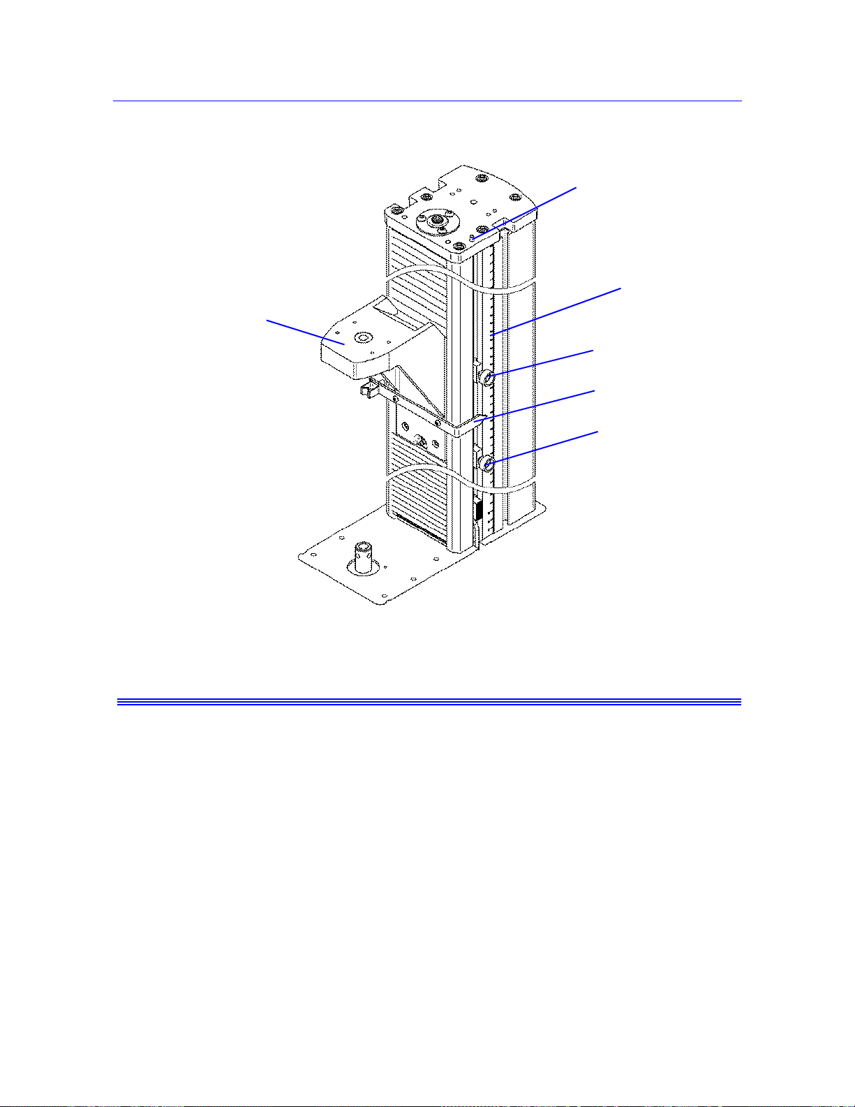
Set the crosshead limit stops
Caution
Limit switch rod
Upper limit stop
Measurement
scale
Crosshead
Limit switch
actuator
Lower limit
stop
Move Off a Crosshead Limit Stop
Product Support: www.instron.com
Figure 3-1. Setting Limit Stops
Do not use limit stops to end a test.
The limit stops are not intended to be an end of test condition to end every test. Repeated use
of the limit stops in this way may cause excessive wear, which can result in the limit stop
failing to stop the crosshead. Proper end of test conditions can be set from the software.
Refer to the online help system for further assistance.
When the crosshead contacts either the upper or lower limit stop, the test stops. If this
happens, use the jog buttons to move the crosshead off the limit stop. Press the button to
move the crosshead off the upper limit stop. Press the button to move the crosshead off
the lower limit stop. The
TEST IN PROGRESS indicator light illuminates when you move
the crosshead.
3-11
Page 46

Chapter: Testing Specimens
Warning
Set the limits for a transducer
Set the load frame limit stops to limit crosshead tra vel, and set adequate transducer
limits to ensure the safe operation of the testing system.
Set all available limits before using the system to avoid crosshead overtravel, contact
between grips and fixtures, overloading any component of the load string, or overtravel of a
contacting extensometer.
Although you can set limits for a transducer in the sof tware, always ensure that the physical
limit stops on the load frame are also set.
Always calibrate the transducer before you enable the limits.
1. Click on the icon for the transducer in the system settings area of the console.
2. In the first tab, select the transducer configuration in the Transducer field.
3. Click the Limits tab.
4. Enter a value for the Minimum limit and set an action that the system performs if it
reaches the minimum limit.
If you change the units for a field, the software converts the corresponding value to its
equivalent value in the new units. Therefore, you must re-enter the correct value based
on the new units.
5. Enter a value for the Maximum limit and set an action that the system performs if it
reaches the maximum limit.
6. Click Enable to activate these limits.
The system activates the limits and disables the fields in this dialog. To make further
changes to these limits, you must first uncheck Enable to activate these fields again. If
Enable is unchecked, the system stops monitoring the transducer limits.
Balance a transducer
Calibrate the transducer before you balance it.
3-12 M10-16245-EN
Page 47

1. Make sure that no specimen is installed.
2. Click on the icon for the transducer in the system settings area of the console.
3. In the first tab, select the transducer configuration in the Transducer field.
4. Click the Balance button.
You can also set a soft key to Balance a specific source transducer or Balance all.
Stop a test
You can stop a test by using hardware controls on the machine or settings in the software.
The following sections describe the different ways to stop a test.
Control Panel Buttons
Sto p a t es t
Press the STOP button on the control panel to stop the crosshead during or after a test. The
crosshead remains in its current position.
Press the
gauge length position specified during test setup.
RETURN button on the control panel to stop a test and return the crosshead to the
Emergency Stop Button
Figure 3-2. Emergency Stop Button
The Emergency Stop button is a large, round, red button on the testing system. Press this
button to stop the test as soon as possible when a condition develops that:
Product Support: www.instron.com
3-13
Page 48

Chapter: Testing Specimens
• Could affect the safety of persons operating the system.
• Could damage the specimen, load frame, or test fixtures.
Investigate and resolve the situation that caused the use of the Emergency Stop button before
you reset the system.
When operated, the Emergency Stop button locks into the closed position and the system is
disabled until you reset the button and re-enable the load frame.
To reset the Emergency stop button and re-enable the load frame:
1. Rotate the Emergency Stop button a quarter-turn clockwise until it resets.
2. In Bluehill software, click on the Frame button in the console area to open the Load
Frame Settings dialog.
3. Click the Frame tab.
4. Click Enable frame.
5. Click Done to close the dialog box. The
illuminates when the frame is enabled.
Crosshead Limit Switches
The test stops if the crosshead contacts the upper or lower limit stops. If this happens, move
the crosshead away from the limit by pressing the or jog buttons.
Software Controls
When the system encounters a pre-set limit or event set from the software, the test stops. The
crosshead may stop or return to the gauge length position, depending on the test stop action
setting in the software.
Shut down the system
Wait until the system completes all active tasks before shutting it off or disconnecting the
electrical power. The system may be engaged in recalculations or printing tasks after the test
has run.
FRAME READY light on the control panel
Shut off the power to the system before you:
• Perform any maintenance procedure on the load frame.
3-14 M10-16245-EN
Page 49

Troubleshooting
• Disconnect the main power cable.
• Move the load frame.
• Connect or install optional components or accessories.
To turn the system off:
1. Complete the test and ensure that the TEST IN PROGRESS indicator light no longer
illuminates.
2. Remove the specimen.
3. Exit the software and turn off the computer and printer using the normal shutdown
procedure.
4. Shut off all the other components or accessories to the test system.
5. Switch the power for the load frame to the Off (
no longer illuminates.
Troubleshooting
The following sections list some of the things that might happen to interrupt your testing and
what you need to do to resume testing.
A Software Transducer Limit Trips
When the system encounters a pre-set limit or event set from the software, the test stops.
If the system trips a transducer limit, you must remove the condition that caused it to trip
before you can reset the limit. To remove the condition, use the jog controls on the frame to
drive the crosshead in the opposite direction and remove the force being applied to the
transducer. For example, if you set a load of 10 kN and the crosshead moves to or beyond a
point that imposes a load of 10 kN on the specimen, you cannot reset the limit until you
remove the limit condition.
O) position. The POWER indicator light
1. Use the jog buttons to drive the crosshead in the direction necessary to remove the limit
condition.
2. Click on the icon for the transducer that you want to work on.
3. Click the Limits tab.
The label for the Enabled check box for the tripped limit changes to Tripped.
4. Click to uncheck the box. The label reverts back to Enabled.
Product Support: www.instron.com
3-15
Page 50

Chapter: Testing Specimens
Warning
5. Check the box again to re-enable the limit.
A Crosshead Travel Limit Trips
When the crosshead contacts either the upper or lower limit stop, the test stops. If this
happens, use the jog buttons to move the crosshead off the limit stop. Press the button to
move the crosshead off the upper limit stop. Press the button to move the crosshead off
the lower limit stop. The
the crosshead.
Second Level Limit Stops
The second level limit switch acts as a backup if the first level switch (the limit stops)
malfunctions. Activating a second-level limit switch disables the drive system so you cannot
move the crosshead. The second level limits are internal to the machine and cannot be
manually adjusted.
TEST IN PROGRESS indicator light illuminates when you move
Hazard - Identify and resolve the condition that caused the operation of the
secondary overtravel limit before you use the testing system.
Operation of a secondary overtravel limit indicates a serious problem with your
testing system, not least that the primary overtravel limit may have failed. Identify
and resolve the condition that caused the secondary overtravel limit to trip before
you use the testing system again. Contact the Instron service department for
assistance.
You press the Emergency Stop button
Refer to “Emergency Stop Button” on page 3-13.
The System Shuts down Unexpectedly
1. To verify that power has been disabled, ensure that the POWER indicator is not
illuminated.
2. Save your existing data.
3. Exit the software program.
4. Before you resume testing, determine why the system shut down and take the necessary
steps to avoid repeating the action. Check the following:
• Are all cables connected?
3-16 M10-16245-EN
Page 51

Troubleshooting
Check that all the cables in the testing system are connected securely.
• Did someone inadvertently press the Emergency Stop button?
Refer to “Emergency Stop Button” on page 3-13.
• Did the fuse on the power supply blow?
Refer to the System Support manual for instructions on replacing a fuse.
5. When you have resolved the problem, switch on the frame and start the software
program. The system should reset itself. Verify that the
POWER indicator light
illuminates.
Product Support: www.instron.com
3-17
Page 52

Chapter: Testing Specimens
3-18 M10-16245-EN
Page 53

Appendix A
Conformance Documents
• Certificate of Conformance . . . . . . . . . . . . . . . . . . . . . . . . . . . . . . . . . . . . . . . . . . A-2
The copy of the certificate on the following page is a generic version. Refer to the original
certificate supplied with your system for specific details.
A-1
Page 54

Chapter: Conformance Documents
English - Original
EC Declaration of conformity for machinery
(Machinery Directive 2006/42/EC, Annex II., sub. A)
Manufacturer: Instron, a divi sion of Illinois Tool Wo rks
Address: 825 University Ave., Norwood, MA, 02062, USA
Name and add r ess of the person authorised to compile the technica l file:
Name: Jim Rose
Address: Instron – Division of ITW Limited , Coronation R oad, High Wycombe,
Buckinghamshire, HP12 3SY, United Kingdom.
Herewith declares that testing machines series T2020, 3300, 5500, 5500A, 5800, 5900
and in particular the machine identified as
Model/ Description :
Serial Number:
x
is in conformity with the relevant provisions of the
Machinery Directive (2006/42/EC)
x is in conformity with the provisions of the following other EC-Directives
EMC-Directive 2004/108/EC
And furthermore, we declare that
x the applicable parts/clauses of the following European harmonised standards published in
the Official Journal have been used
BS EN ISO 12100 (2010) Safety of Machinery. General principles for design.
Risk assessment and risk reduction.
BS EN 61326-1 (2006) Electrical Equipment for measurement, control and
laboratory use - EMC requirements.
BS EN 61010-1 (2001) Safety Requirements for Electrical Equipment for
Measurement Control and Laboratory Use.
Place and date of origin Signature:
Norwood, MA., USA
Certificate of Conformance
A-2 M10-16245-EN
Page 55

Index
A
at GL (gauge length) . . . . . . . . . . . . . . . . . . 2-5
at GL indicator. . . . . . . . . . . . . . . . . . . . . . . 2-5
at ZERO (zero extension point). . . . . . . . . . 2-5
B
balance transducer. . . . . . . . . . . . . . . . . . . 3-12
C
calibrate transducer . . . . . . . . . . . . . . . . . . . 3-6
contact information . . . . . . . . . . . . . . . . . . . 1-8
control panel . . . . . . . . . . . . . . . . . . . 2-3 to 2-5
controls
at GL. . . . . . . . . . . . . . . . . . . . . . . . . . . . .
at ZERO . . . . . . . . . . . . . . . . . . . . . . . . . . 2-5
fine jog . . . . . . . . . . . . . . . . . . . . . . . . . . . 2-5
jog down. . . . . . . . . . . . . . . . . . . . . . . . . . 2-5
jog up . . . . . . . . . . . . . . . . . . . . . . . . . . . . 2-5
power . . . . . . . . . . . . . . . . . . . . . . . . . . . . 2-5
reset GL . . . . . . . . . . . . . . . . . . . . . . 2-5, 3-9
return . . . . . . . . . . . . . . . . . . . . . . . . . . . . 2-5
set zero extension point . . . . . . . . . . 2-5, 3-9
specimen protect. . . . . . . . . . . . . . . . . . . . 2-5
start test . . . . . . . . . . . . . . . . . . . . . . . . . . 2-5
stop test. . . . . . . . . . . . . . . . . . . . . . . . . . . 2-5
create
sample
with existing method. . . . . . . . . . . . . . .
crosshead
travel limits, moving off a limit . .
travel limits, second level limits. . . . . . . 3-16
3-11, 3-16
2-5
3-4
F
fine jog. . . . . . . . . . . . . . . . . . . . . . . . . . . . . 2-5
frame control panel . . . . . . . . . . . . . . 2-3 to 2-5
I
Instron
contact information. . . . . . . . . . . . . . . . . .
product support . . . . . . . . . . . . . . . . . . . . . 1-8
1-8
J
jog keys . . . . . . . . . . . . . . . . . . . . . . . . . . . . 2-5
L
labeling
safety and information . . . . . . . . .
limit stops
moving off a limit. . . . . . . . . . . . .
second level limits. . . . . . . . . . . . . . . . . . 3-16
1-6 to 1-7
3-11, 3-16
N
name
sample. . . . . . . . . . . . . . . . . . . . . . . . . . . .
3-5
P
power indicator. . . . . . . . . . . . . . . . . . . . . . . 2-5
power input connector . . . . . . . . . . . . . . . . . 2-1
product support. . . . . . . . . . . . . . . . . . . . . . . 1-8
R
reset gauge length (GL) . . . . . . . . . . . . 2-5, 3-9
return button. . . . . . . . . . . . . . . . . . . . . . . . . 2-5
return in progress indicator . . . . . . . . . . . . . 2-5
S
safety and information labeling . . . . 1-6 to 1-7
safety limits
second level limits. . . . . . . . . . . . . . . . . .
sample
create
with existing method . . . . . . . . . . . . . . .
name . . . . . . . . . . . . . . . . . . . . . . . . . . . . . 3-5
3-16
3-4
Index-1
Page 56

T
sample file
create
with existing method. . . . . . . . . . . . . . .
set zero extension point. . . . . . . . . . . . 2-5, 3-9
specimen protect button. . . . . . . . . . . . . . . . 2-5
start
new sample
with existing method. . . . . . . . . . . . . . .
start test button . . . . . . . . . . . . . . . . . . . . . . 2-5
start test indicator . . . . . . . . . . . . . . . . . . . . 2-5
starting
system. . . . . . . . . . . . . . . . . . . . . . . . . . . .
stop test button. . . . . . . . . . . . . . . . . . . . . . . 2-5
stop test indicator. . . . . . . . . . . . . . . . . . . . . 2-5
support. . . . . . . . . . . . . . . . . . . . . . . . . . . . . 1-8
system startup . . . . . . . . . . . . . . . . . . . . . . . 2-2
3-4
3-4
2-2
T
technical support . . . . . . . . . . . . . . . . . . . . . 1-8
test
create new sample
with existing method. . . . . . . . . . . . . . .
transducer
balance . . . . . . . . . . . . . . . . . . . . . . . . . .
calibrate . . . . . . . . . . . . . . . . . . . . . . . . . . 3-6
limits
set . . . . . . . . . . . . . . . . . . . . . . . . . . . .
travel limits
second level limits . . . . . . . . . . . . . . . . .
3-4
3-12
3-12
3-16
Index-2 M10-16245-EN
Page 57

Page 58

Product Support: www.instron.com
 Loading...