

Issue C April 1995
Instron
Model 4400
Universal Testing System
M10-94400-1
Operator’s Guide

This document and the information that it contains are the property of Instron
Corporation. Rights to duplicate or otherwise copy this document and rights to
disclose the document and the information that it contains to others and the right
to use the information contained therein may be acquired only by written
permissionsigned by a duly authorized officer of Instron Corporation.
Proprietory Rights Notice
© Copyright 1995 Instron Corporation

Amendment
Number
Amendment Incorporation Record
Brief Description of
Content
ECR
Numberr
Preliminary Pages
Person
Incorporating
Amendment
1
Reverse Strain Mode Switch
Settings
B3887 NCW
2
3
4
5
6
7
8
9
10
iii

Preliminary Pages M10-94400-1
Amendment Incorporation Record
Amendment
Number
Brief Description of
Content
ECR
Numberr
Person
Incorporating
Amendment
11
12
13
14
15
Revision Record
Revision ECR No.
iv

Preliminary Pages
Materials testing systems are potentially hazardous.
Materials testing involves inherent hazards from high
forces, rapid motions and stored energy. You must be
aware of all moving and operating components which
are potentially hazardous, particularly the actuator in a
servohydraulic testing system or the moving crosshead
in an electromechanical testing system.
Whenever you consider that safety is compromised,
press the Emergency Stop button to stop the test and isolate the testing system from hydraulic or electrical
power.
Carefully read all relevant manuals and observe all
Warnings and Cautions. The term Warning is used
where a hazard may lead to injury or death. The term
Caution is used where a hazard may lead to damage to
equipmentortolossofdata.
Ensure that the test set-up and the actual test you will
be using on materials, assemblies or structures constitutes no hazard to yourself or others. Make full use of
all mechanical and electronic limits features. These are
supplied for your safety to enable you to prevent movement of the actuator piston or the moving crosshead beyond desired regions of operation.
The following pages detail various general warnings
that you must heed at all times while using materials
testing equipment. You will find more specific warnings and cautions in the t ext whenever a potential hazard exists.
Your best safety precautions are to gain a thorough understanding of the equipment by reading your instruction manuals and to always use good judgement.
v

Preliminary Pages M10-94400-1
Warning
Disconnect the electrical power supply before removing the covers to electrical equipment.
Disconnect the equipment from the electrical power supply before removing any electrical safety covers or replacing fuses. Do not reconnect the power source while
the covers are removed. Refit covers as soon as possible.
Disconnect power supplies before removing the covers to rotating machinery.
Disconnect the equipment from all power supplies before removing any cover which gives access to rotating
machinery. Do not reconnect any power supply while
the covers are removed unless you are specifically instructed to do so in the manual. If the equipment needs
to be operated to perform maintenance tasks with the
covers removed, ensure that all loose clothing, long hair,
etc. is tied back. Refit covers as soon as possible.
Shut down the hydraulic power supply and
discharge hydraulic pressure before disconnecting any hydraulic fluid coupling.
Do not disconnect any hydraulic coupling without first
shutting down the hydraulic power supply and discharging stored pressure to zero. Tie down or otherwise secure all pressurized hoses to prevent movement during
system operation and to prevent the hose from whipping
about in the event of a rupture.
vi

Warning
Do not release gas connections without first disconnecting the gas supply and discharging any residual pressure
to zero.
Use protective shields whenever a risk of injury to operators and observers exists from the failure of a test specimen, assembly or structure, particularly where explosive
disintegration may occur.Due to the wide range of specimen materials, assemblies or structures that may be tested,
any hazard resulting from the failure of a test specimen, assembly or structure is entirely the responsibility of the
owner and the user of the equipment.
Preliminary Pages
Shut off the supply of compressed gas and
discharge residual gas pressure before disconnecting any compressed gas coupling
Use protective shields or screens if any possibility exists of a hazard from the failure of
a specimen, assembly or structure under
test.
Protect electrical cables from damage and
inadvertent disconnection.
The sudden loss of controlling and feedback signals
which can result from a disconnected or damaged cable
causes an open loop condition which may drive the actuator or crosshead rapidly to its extremes of motion.
Protect all electrical cables, particularly transducer cables, from damage. Never route cables across the floor
without protection, nor suspend cables overhead under
excessive strain. Use padding to avoid chafing where cables are routed around corners or through wall openings.
vii

Preliminary Pages M10-94400-1
Warning
Wear protective clothing when handling
equipment at extremes of temperature.
Materials testing is often carried out at non-ambient temperatures using ovens, furnaces or cryogenic chambers.
Extreme temperature means an operating temperature exceeding 60 °C (140 °F) or below 0 °C (32 °F). You must
use protective clothing, such as gloves, when handling
equipment at these temperatures. Display a warning notice concerning low or high temperature operation whenever temperature control equipment is in use. You
should note that the hazard from extreme temperature
can extend beyond the immediate area of the test.
Take care when installing or removing a
specimen, assembly or structure.
Installation or removal of a specimen, assembly or structure involves working inside the hazard area between the
grips or fixtures. Keep clear of the jaws of a grip or fixture at all times. Keep clear of the hazard area between
the grips or fixtures during actuator or crosshead movement. Ensure that all actuator or crosshead movements
necessary for installation or removal are slow and,
where possible, at a low force setting.
viii

Warning
The actuator or crosshead will immediately respond to
manual control settings when the system is placed offline from computer control. Before transferring to manual control, make sure that the control settings are such
that unexpected actuator or crosshead movement cannot
occur.
The robot in an automated testing system presents a hazard because its movements are hard to predict. The robot
can go instantly from a waiting state to high speed operation in several axes of motion. During system operation ,
keep away from the operating envelope of the robot. Deactivate the robot before entering the envelope for any
purpose, such as reloading the specimen magazine.
Preliminary Pages
Do not place a testing system offline from
computer control without first ensuring that
no actuator or crosshead movement will occur upon transfer to manual control.
Keep clear of the operating envelope of a
robotic device unless the device is de-activated.
ix

Preliminary Pages M10-94400-1
Table of Contents
Chapter Page
1 Introduction
Outline .........................................................................1-1
Introduction..................................................................1-2
About this Manual...............................................1-3
Product Support..................................................1-3
General Characteristics...............................................1-4
Console Components..................................................1-7
Front Panel..................................................................1-8
Main Panel Section.............................................1-8
Display Panel Section.........................................1-10
Limits Panel Section ...........................................1-10
Crosshead Control Section.................................1-11
Internal Status Indicators ....................................1-12
Recorders ...........................................................1-12
Console Internal Functions..........................................1-14
Central Processing Unit (CPU) ...........................1-14
Crosshead Control Function ...............................1-14
Load Sensor Conditioner....................................1-14
Strain Sensor Conditioner...................................1-15
IEEE-488 Interface .............................................1-15
2 Specifications
Introduction..................................................................2-2
Specifications...............................................................2-3
3 Installation
Outline .........................................................................3-1
General Considerations...............................................3-2
x

Preliminary Pages
Table of Contents (continued)
Chapter Page
3 Installation
(continued)
Console Connections...................................................3-3
Mounting the Console.........................................3-3
Attaching the Console...................................3-3
Mounting the Console Bracket......................3-4
Connector Panel.................................................3-5
Installing Cables .................................................3-7
Cabling for Optional Equipment..........................3-9
Cables...........................................................3-9
Analog Output Connector .............................3-9
Opening the Console...................................................3-11
4 Function Of Controls
Outline .........................................................................4-1
Preliminary Considerations..........................................4-2
Function Of Controls....................................................4-3
Main Panel..........................................................4-3
Display Section...................................................4-12
Limits Section .....................................................4-14
Data Storage ...............................................................4-16
Nonvolatile Memory............................................4-16
System Reset .....................................................4-16
Volatile Memory ..................................................4-16
Resident Test Program Overview................................4-20
Self Test Routine .........................................................4-23
Self Test - Part 1 .................................................4-23
Self Test - Part 2 .................................................4-24
Self Test Result - No Failures .............................4-24
xi

Preliminary Pages M10-94400-1
Table of Contents (continued)
Chapter Page
4 Function Of Controls
(continued)
Self Test Result - Failures...................................4-25
Self Test Result Display......................................4-25
Version Number...........................................................4-31
Selecting Operating Units............................................4-32
Switching Units ...................................................4-32
Operating Units for Self Identified Load Cells
and Load Frames................................................4-33
Operating Units for Non-Self Identified Load
Cells and Load Frames.......................................4-34
Area...................................................................4-35
Energy Units .......................................................4-35
5 System Operation
Outline .........................................................................5-1
Operating Considerations............................................5-2
Pretest Procedures......................................................5-3
Turn Instrument On: Warm-up.....................................5-4
Self Test Routine At Power Up ....................................5-5
System Reset At Initial Power Up................................5-7
Load Calibration ..........................................................5-8
Overview ............................................................5-8
Electrical Calibration of Self Identifying
Load Cells ..........................................................5-9
Manual Calibration of Self Identifying
Load Cells ..........................................................5-10
Electrical Calibration of Non-Self Identifying
Load Cells...........................................................5-12
xii

Preliminary Pages
Table of Contents (continued)
Chapter Page
5 System Operation
(continued)
Manual Calibration of Non-Self Identifying
Load Cells..........................................................5-13
Load Weighing System Balance ........................5-15
Calibration And Balance Errors...........................5-16
Strain Calibration.........................................................5-18
Overview.............................................................5-18
Strain Operating Mode........................................5-18
Strain Gauge Extensometers..............................5-20
Electrical Calibration of Self Identifying Strain
Gauge Extensometers ......................................5-22
Manual Calibration of Strain Gauge
Extensometers...................................................5-22
Extensometers - Operating Notes.......................5-25
Display Panel...............................................................5-26
Description..........................................................5-26
Operation............................................................5-26
Establish Gauge Length ..............................................5-28
Electronic Limits...........................................................5-30
Operating Notes - Limits Panel...........................5-30
Operation............................................................5-31
Set Crosshead Travel Limit Stops...............................5-34
Set Crosshead Speed .................................................5-35
Crosshead Jog Control................................................5-37
Area Compensation.....................................................5-38
Install Specimen ..........................................................5-42
Set Testing Area ..........................................................5-43
Run a Test ...................................................................5-45
xiii

Preliminary Pages M10-94400-1
Table of Contents (continued)
Chapter Page
6 System Options
Overview......................................................................6-1
Introduction..................................................................6-2
Strip Chart Recorder....................................................6-3
Description..........................................................6-3
Specifications......................................................6-4
Power Requirements ....................................6-6
Installation...........................................................6-7
Operation............................................................6-8
Pen Scaling...................................................6-8
Pen Calibration .............................................6-9
X-Y Recorder...............................................................6-12
Description.........................................................6-12
Specifications......................................................6-13
Installation...........................................................6-15
Power Requirements ....................................6-15
Signal Input Connection................................6-15
Operation............................................................6-16
Initial Setup...................................................6-16
Calibration.....................................................6-19
Time Base Operation....................................6-22
Normal Operation..........................................6-23
Printer..........................................................................6-24
Description..........................................................6-24
Installation...........................................................6-24
Operation............................................................6-25
Printout Format...................................................6-25
Printer Units........................................................6-26
xiv

Preliminary Pages
Table of Contents (continued)
Chapter Page
6 System Options
(continued)
AC/DC Strain Conditioner............................................6-30
Specifications......................................................6-31
Installation...........................................................6-31
Operation............................................................6-32
Preset Points ...............................................................6-34
Description..........................................................6-34
Operation............................................................6-35
Energy .........................................................................6-37
Description..........................................................6-37
Operation............................................................6-37
Cycle Counter..............................................................6-39
Pip Control...................................................................6-41
Air Kit Option ...............................................................6-44
Overview.............................................................6-44
Description..........................................................6-44
Operation............................................................6-45
Manual Operation .........................................6-46
Grip Control Function Operation ...................6-47
Pretension and Excess Tension Operation...6-47
Automatic Start Operation.............................6-48
Automatic Release Operation .......................6-49
Set pretension Level .....................................6-49
Set Excess Tension Level .............................6-50
Time Delays ..................................................6-50
Continuous Pretension Testing.....................6-50
xv

Preliminary Pages M10-94400-1
Table of Contents (continued)
Chapter Page
7 Test Check List
8 Maintenance
Overview......................................................................8-1
Introduction..................................................................8-2
General...............................................................8-2
Special Maintenance Considerations..................8-2
Preventive Maintenance ..............................................8-3
Cleaning - Control Console.................................8-3
Error Messages ...........................................................8-4
Overview.............................................................8-4
Displaying Error Messages.................................8-4
Rear Panel Indicators ..................................................8-10
Rear Panel Indicators .........................................8-10
General.........................................................8-10
Power Supply Condition Indicators...............8-11
Green Test LEDs...........................................8-11
Red Activity LEDs .........................................8-12
Red Latch Indicator LEDs.............................8-13
IEEE-488 Interface Indicators.......................8-14
Summary of Operating Sequence for
Rear Panel Indicators ..................................8-15
Fault Indications ..........................................................8-16
Appendix A Test Planning
Applications .................................................................A-2
Load Requirements .....................................................A-4
Selection Of Grips........................................................A-5
xvi

Preliminary Pages
Table of Contents (continued)
Chapter Page
Appendix A Test Planning (continued)
Establishing Gauge Length..........................................A-7
Selection Of Testing Speed .........................................A-8
Strain Rate...................................................................A-9
Area Compensation.....................................................A-10
Description..........................................................A-10
Determining Stress Range..................................A-11
Limitations Due To Load Cell Capacity ...............A-12
Chart Magnification......................................................A-14
Appendix B Glossary
xvii

Preliminary Pages M10-94400-1
List of Illustrations
Figure Page
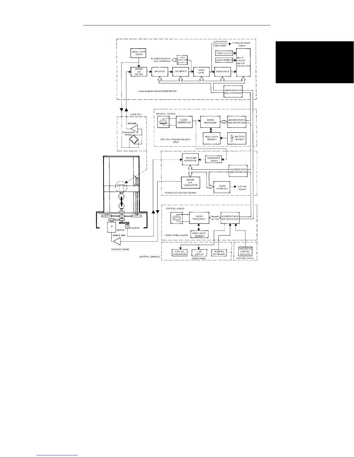
1-1. Functional Block Diagram............................................1-5
1-2. Control Console Front Panel ......................................1-9
3-1. Console Rear Panel Connectors .................................3-6
3-2. Rear Panel Cable Arrangement...................................3-8
3-3. Access to Interior of Console.......................................3-12
4-1. Main Panel...................................................................4-3
4-2. Display Section............................................................4-12
4-3. Limits Section ..............................................................4-14
4-4. Console Section Numbers Assigned to
Main Panel Display for Self Test Result......................4-26
4-5. Coding of Display Results for Self Test Result ............4-27
4-6. Characters Displayed in Self Test Result....................4-27
6-1 Model 4400 X-Y Recorder Panel.................................6-17
6-2. Typical Test Curve with Preset Points..........................6-34
8-1. Rear Panel Indicators .................................................8-12
8-2. Closeup Detail of Console Status and
Fault Indicators............................................................8-13
xviii

Preliminary Pages
List of Tables
TablePage
3-1. Series 4400 Console Option Cables............................3-9
3-2 Analog Output Connector Pin Assignments ................3-10
4-1. Main Panel Functions..................................................4-3
4-2. Display Section Functions ...........................................4-12
4-3. Limits Section Functions..............................................4-14
4-4. Variables and Functions in Nonvolatile
Memory........................................................................4-17
4-5. Control Console Sections ............................................4-26
4-6. Characters Possible in Self Test Result for
Each Digit of Main Panel Display.................................4-29
4-7. Operating Units for Self-Identified Load
Cells 4-33
5-1. Low Capacity Load Cells Calibration Data ..................5-13
5-2. Transducer Calibration/Balance Errors........................5-17
6-1. Strip Chart Recorder Supplies.....................................6-6
6-2. Recorder Line Voltage Selection .................................6-7
6-3. Calibration Signal for Load Cells .................................6-10
6-4. Recorder Supplies.......................................................6-14
6-5. Chart Speed Conversions............................................6-22
6-6. Strain Units Printout.....................................................6-26
6-7. Energy Units Printout...................................................6-27
6-8. Printout with Strain as Independent
Variable........................................................................6-28
6-9. Printout with Extension as Independent
Variable........................................................................6-28
xix

Preliminary Pages M10-94400-1
List of Tables (continued)
Table Page
6-10. Example Pip Delay Values vs Test Speeds.................6-43
6-11. Air Kit Functions ..........................................................6-46
8-1. Sections of the Control Console..................................8-5
8-2. Error Messages ...........................................................8-7
8-3. LED Error Codes for IEEE-488 Section Tests .............8-14
8-4. Fault Indications ..........................................................8-16
A-1. Gripping Techniques....................................................A-6
A-2. Typical Testing Speed Ranges for Various
Materials......................................................................A-8
xx

Preliminary Pages
xxi
Preliminary Pages M10-94400-1
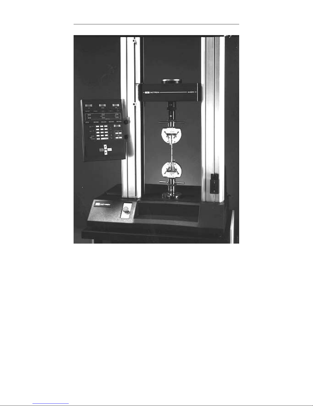
Frontispiece.Series 4400 Universal Testing System
xxii

Outline
Chapter 1
Introduction
Introduction
• Introduction ........................Page 1-2
• General Characteristics ...............Page 1-4
• Console Components .................Page 1-7
• Front Panel.........................Page 1-8
• Console Internal Functions ............Page 1-14
The Instron Series 4400 Universal Testing Instruments are
electromechanical systems employing the latest printed circuit board technology to provide a small, light and efficient
testing system. This manual describes the functions and operation of the Control Console. Other manuals include
Load Frame operating instructions for each of the Series
4400 systems and an IEEE Interface User’s Guide.
This chapter describes:
• The features and functions of the Series 4400
Systems
• The physical layout of the system
• Some of the optional accessories available for the
system
1-1

Introduction M10-94400-1
Introduction
The Instron Series 4400 Universal Testing Instrument is
a materials testing instrument designed to test the
strength of a wide variety of materials. The system is
made up of a load frame, in which a specimen of the
test material is mounted, that applies a tension or compression load to the specimen, and a control console that
provides the calibration, test setup, and test operating
controls. The control console is compact enough to
mount directly on the load frame, eliminating the need
for a separate support table or workbench.
The Series 4400 Control Console includes an operator’s
front panel with controls that offer complete communications with the system through a numeric keypad, pushbutton selection switches and Liquid Crystal Displays
(LCDs).
The Console front panel is divided into sections according
to functional groupings of controls. For example, a Main
section contains a numeric keypad and digital display for
data input, a Limits section sets up the electronic limits,
and a Display section contains LCD displays of real-time
values of test parameters. These panel sections are described more fully later in this chapter.
1-2
Optional interfacing is available for an X-Y or a strip chart
recorder, a printer, and a programmable computer. These
options may be specified with your initial order or added
later to expand the capabilities of your testing system.

About this Manual
The purpose of this manual is to provide a basic understanding of the Control Console and its principles of operation. It contains specifications, cable installation,
component and control descriptions, operating details
for both basic and optional features, and maintenance.
Appendices contain an introduction to materials testing
and a glossary of terms related to materials testing.
In addition to this manual, there is also a manual covering the installation, maintenance, and parts list for the
load frame. Accessories, such as the strip chart and X-Y
recorders, printer, and most grips and extensometers,
come with their own separate instruction manuals.
Product Support
If you encounter any problems with using or maintaining your testing instrument, or if you want to order accessories or parts, you can obtain answers to your
questions or place orders by calling Instron Service, using the list below:
Introduction
Introduction
In the United States: 1-800-473-7838
In Canada: 1-800-461-9123
In all other regions of the world: Nearest Instron
Service Office
A listing of international Instron Sales and Service offices, including addresses and telephone numbers, can
be found on the back cover of this manual.
1-3

General Characteristics M10-94400-1
General Characteristics
The Series 4400 control system is made up of two major
subsystems: a crosshead drive and control system, that
applies tensile or compressive loading to a specimen;
and a highly sensitive load weighing system, that measures the loading of a specimen. Figure 1-1 is a functional
block diagram showing the interfacing of these two systems, and the signal flow within the overall instrument.
During a test, results occur as tracked (instantaneous)
values of load, extension and strain or, after a test, as
stored break and peak values of these parameters. Total
energy and load and energy values at preset points are
also available as stored parameters. Several choices of
analog and digital output devices are available as options for viewing and recording test results.
The control console provides control, data acquisition
and data readout functions for the load frame. All operations are directed by a microprocessor-based central
processing unit (CPU). The crosshead control network
allows programmable crosshead speeds and provides
digital control of the crosshead position. The operating
mode of the console data entry and readout functions
can be in English, metric or SI units, as selected by a
switch. A status indicator on the main panel shows the
system of units selected.
1-4
The action of the moving crosshead during a test - stop,
return, or cycle - can be controlled manually by pushbutton switches, or automatically by the functions provided
by the Limits feature. These functions may be based on
the applied load, extension or strain, or to a detected
specimen break.
General Characteristics
Introduction
Figure 1-1. Functional Block Diagram
1-5

General Characteristics M10-94400-1
A CPU-controlled sensor conditioner in the load weighing system allows calibration and balance procedures to
be performed automatically, after you initiate them at
the front panel. The sensor conditioner provides both an
unranged analog and an automatically ranged digital
load signal output suitable for several types of optional
readout devices.
Optional readouts for test results include interfacing for
an X-Y recorder, a strip chart recorder, and an 80 character-width printer.
The console also has provisions for an IEEE-488 interface. This is a General Purpose Instrument Bus (GPIB)
which allows remote supervisory control of test procedures through a programmable computer.
1-6

Console Components
The Series 4400 Control Console contains a single
printed circuit board on which are mounted all of the
electrical components, including the front panel
switches and displays, and rear panel connectors.
The console printed circuit board is the interface for all
connections to the console. The interconnecting cables
from the load frame and load cell, and cabling from optional recorders, printers, and strain measuring devices
plug into connector locations on the rear of the board.
Since the console receives its electrical power from a
d.c. power supply in the load frame, there is no need for
bulky power supplies and cooling fans, and thus a compact size has been achieved.
The Console itself is mounted on the load frame by
means of a special bracket. A friction locking device on
the bracket rides in grooves in the crosshead column covers on the load frame, allowing the console to be moved
to any convenient working height. The bracket is symmetrical, allowing the console to be mounted on either
the right-hand or left-hand column on the frame.
Console Components
Introduction
The main components of the control console are shown
in Figure 1-2. Access to the interior of the console is described in Chapter 4.
1-7

Front Panel M10-94400-1
Front Panel
The Front Panel (Figure 1-2) is divided into four major
sections. The Main section contains a numeric keypad
for data entry of system setup parameters, an LCD display for the numeric input, pushbuttons for such functions as crosshead speed selection, and gauge length
setting, among others. The Display section contains
LCD displays of real-time values of Load, Extension,
and Strain, while the Limits section sets electronic limits
for the system. The last section is the Crosshead Control
section, in which manual controls for crosshead positioning are located.
Main Panel Section
The Main Panel section consists of test function entry
keys, a numeric keypad and a 4-digit LCD display.
Status indicators on the left-hand side of the panel, when
lit, signify that a fault has occurred. The current units
(S.I., English, metric) in use by the testing system are
also shown in this area. The panel provides the following functions:
• Load cell calibration
• Crosshead speed selection
• Gauge length
1-8
• Area compensation
• Testing area definition
• Strain transducer calibration
• Printer operation
• IEEE bus enable/disable
• Special Software - Diagnostics

Front Panel
Introduction
Figure 1-2. Control Console Front Panel
1-9

Front Panel M10-94400-1
Display Panel Section
The Display Panel section contains three 4-digit LCD
displays and control keys to allow load, extension, and
strain to be tracked during a test, and the peak and break
values of these parameters to be observed. All values are
computed and saved at the end of each test and may be
viewed as needed during and after the test. An indicator
lamp shows the active selection key.
Limits Panel Section
The Limits Panel section allows you to specify what action
the system takes whenmaximumand minimum values of
load, extension or strain occur during a test. The electronic
Limits function acts to protect valuable specimens, grips,
and test fixtures from the effects of crosshead overtravel
and possible collision.
You should always set limits and assign a crosshead action before starting a test. Enter limits values using the
keypad and view them on the Main Panel Display.
1-10
Descriptions of the Limits Panel control functions are
found in Table 4-3.
The Limits Panel section allows a crosshead action to be
specified that is independently based on the following
limit conditions during a test:
LOAD - minimum, maximum
EXTENSION - minimum, maximum
STRAIN - minimum, maximum
BREAK - detection

The action assigned to a limit can be:
STOP - stop crosshead at current position.
RETURN - return crosshead to gauge length.
CYCLE - change direction of crosshead motion at
the limit.
OFF - no action
An indicator lamp lights at the active limit and at the related crosshead action key. A STATUS indicator lamp is lit
whenever a limit is set to control a crosshead action. Whenever a STOP or RETURN action occurs as the result of a
limit, the related STATUS lamp flashes.
Crosshead Control Section
The crosshead control keys, located at the bottom of the
Front Panel are used for manually controlling crosshead
functions. The STOP, UP, DOWN and RETURN keys
each have an associated indicator lamp which is lit when
the function of the key, as described below, is controlling the crosshead.
Front Panel
Introduction
STOP - crosshead stops.
UP - crosshead moves up at programmed speed.
DOWN - crosshead moves down at programmed
speed.
RETURN - crosshead returns at a speed which increases exponentially to maximum and then decreases exponentially to stop crosshead at gauge
length.
1-11

Front Panel M10-94400-1
Internal Status Indicators
A series of Light Emitting Diode (LED) indicators are
mounted on the circuit board inside the console, but are
visible through a window cutout in the rear panel. These
indicators report the condition of power supply voltages,
the pass/fail condition of some CPU functions during the
Self-Diagnostic Test, and onthe activity of CPU circuits
during normal operation. Refer to Chapter 8, Maintenance, for a detailed description of the Status LEDs.
Recorders
You have a choice of using an X-Y recorder or a strip
chart recorder as a readout device. The X-Y recorder allows two test parameters, often Load versus Strain, to be
plotted against each other. A strip chart recorder, on the
other hand, plots one parameter versus time. Since crosshead speed can be converted directly into time, the
speed of the strip chart can be correlated with crosshead
speed and a plot of a test parameter, such as Load or
Strain, versus crosshead speed can be obtained.
1-12
Load and strain ranging are performed at the front panel
of the recorder itself. This allows you to select an operating range for each parameter from a predefined list of
gain factors. The operating range of the recorder is defined as the percentage of the maximum capacity of the
installed load cell that causes a full scale reading on the
recorder.
The specific recorders available for the Series 4400 Testing System are:
XY/YT Plotter Cat. No. 2310-901

Front Panel
Single Pen Strip Chart Recorder Cat. No. 2310-904
Double Pen Strip Chart Recorder Cat. No. 2310-905
Introduction
1-13

Console Internal Functions M10-94400-1
Console Internal Functions
In addition to the operator interface and cabling interface functions described previously, the console circuit
board provides a number of internal functions to complete the testing system. These functions include a Central Processing Unit (CPU), a Crosshead Control
function, a Load Sensor Conditioner, a Strain Sensor
Conditioner, and an IEEE-488 Interface function. These
functions are described in the following sections.
Central Processing Unit (CPU)
The CPU is a computer chip that provides the main processing functions for the console. A digital bus originating in this section allows communication with and
control of all other operations, including optional interfacing for peripheral devices. Battery backup in this section allows nonvolatile parameter storage.
Crosshead Control Function
This function provides the interfacing between the load
frame and console for the crosshead control signals. The
encoder output signal provides crosshead position (extension) information that is conditioned and the
crosshead position (extension) determined by the functions in this section. An error signal is developed when
the extension is compared with the commanded
crosshead speed and fed back to the crosshead drive system.
Load Sensor Conditioner
1-14

This function provides interfacing between the load
transducer (load cell) and the console. Functions that
this section supplies are excitation to a load cell, processing of its output signal, and providing calibrated analog
and digital load weighing information to the console and
readout devices.
Strain Sensor Conditioner
This function is located on an optional plug-in board and
is similar to the Load Sensor Conditioner. It provides interfacing between strain measuring extensometers and
the console, and is available as an AC Strain Conditioner (Catalog No. 2210-863). This conditioner is used
with strain gauge extensometers, rationalized long-travel
extensometers, and linear variable displacement
transducers (LVDTs). An AC/DC version (Catalog No.
2210-865) is used with video extensometers and high
resolution digital (HRD) automatic extensometers.
Console Internal Functions
Introduction
IEEE-488 Interface
This function allows a Series 4400 testing system to be
remotely controlled by an external personal computer
through a General Purpose Instrument Bus (GPIB). This
microprocessor-based pc board interacts directly with
the CPU, thus enabling a supervisory program to control
console and load frame functions. The external computer must be able to transfer program messages to and
receive measurement messages and status from the test
instrument. Complete programming information is supplied with the IEEE-488 interface option kit.
1-15

Console Internal Functions M10-94400-1
1-16

Chapter 2
Specifications
• Introduction ........................Page 2-2
• Specifications.......................Page 2-3
This chapter lists physical and electrical specifications
for the Series 4400 Control Console. Load Frame specifications and specifications for the system as a whole are
given in the load frame manual.
Specifications
2-1

Specifications M10-94400-1
Introduction
The following table lists physical and electrical specifications for the Series 4400 Control Console. Specifications for the Load Frame and its components are given
in the load frame manual.
Since system specifications depend, to a large extent, on
the system transducers (load cell, extensometers, etc.) in
use, and the load capacity of the load frame, it is not possible to list system specifications for all possible combinations of load frames and transducers.
The generalized specifications in this chapter will help
you to determine whether your system will meet your individual testing requirements. If you have any questions
about specifications, your regional Instron Sales Engineer will be happy to assist you.
2-2

Specifications
Components
Standard:
Options:
Power Requirements
+5 Vd.c.
+15 Vd.c.
-15 Vd.c.
(All voltages supplied from Load Frame, must be free of
spikes, surges, or sags exceeding 10% of the average
voltage)
Specifications
Main Panel
Display Panel
Limits Panel
Load Sensor Conditioner
RS-232 Interface
Strain Sensor Conditioner
IEEE-488 Interface
Strip Chart Recorder
X-Y Recorder
Printer
Specifications
Operating Performance
Load Weighing Accuracy
±0.01% of full scale or ±0.5% of reading (whichever is
greater) ±1 count on the load display.
Load weighing system meets or surpasses the following
standards: ASTM E4, BS1610, DIN 51221, ISO 7500/1,
EN10002-2, AFNOR AO3-501
2-3

Specifications M10-94400-1
Strain Measurement Accuracy
±0.05% of full scale or ±0.5% of reading (whichever is
greater) ±1 count on the strain display
Strain measurement system meets or surpasses the
following standards: ASTM E83, BS3846, ISO 9513,
EN1002-4
Environmental Requirements
Operating temperature:
+10 to +38 °C (+50 to +100°F)
(other ranges available on request)
Storage temperature:
-40 to +60 °C (-40 to +140°F)
Relative Humidity:
10% to 90% non-condensing
Atmosphere:
Use in normal laboratory conditions.
2-4
Note:
Protective measures may be required if excessive dust, corrosive fumes, electromagnetic
fields or hazardous conditions are present.

Materials
Enclosure: Structural foam
Keyboard: Cleanable mylar surface
with silicon rubber switches.
Dimensions
Height: 406.4 mm (16 in.)
Width: 280 mm (11 in.)
Depth: 58.2 mm (2.3 in.)
Weight 2.7 kg (6 lb) approx.
Specifications
Specifications
2-5

Specifications M10-94400-1
2-6

Outline
Chapter 3
Installation
• General Considerations ...............Page 3-2
• Console Connections .................Page 3-3
• Opening the Console .................Page 3-11
This chapter contains instructions for installing the Series 4400 Console on the load frame and for cabling optional accessories. Installation instructions for the load
frame itself are contained in the load frame instruction
manual.
You will use this chapter to find out how to:
• Connect system cables
• Mount the Console
• Open the console for servicing
Installation
3-1

General Considerations M10-94400-1
General Considerations
Installation of a basic Series 4400 testing instrument is
described in the load frame manual for the system. This
chapter describes how to access the interior of the console and install cabling for optional devices. The basic
cables, Load and Frame, are installed at the factory.
As part of the preparation for a testing routine, you
should connect any cabling required for peripheral readout and control accessories before powering up the system. These accessories include strain measuring devices,
a recorder, printer and a computer. Any panels or circuit
boards required to use these accessories have usually
been installed previously at the factory.
3-2

Console Connections
Mounting the Console
The Series 4400 Console is attached to a console mounting
bracket that is, in turn, mounted on one of the load frame
columns, either directly in grooves in the column cover (table models) or on an extension of the column cover (floor
models). On floor model load frames, the column cover extension can be mounted on either the right-hand or lefthand load frame column, specified at the time of purchase,
but this can be changed later, if necessary. The console is
attached to the mounting bracket with screws, and the
bracket can rotate around a vertical axis to provide a comfortable viewing angle for the console.
Console Connections
Attaching the Console
The console mounting bracket is in two parts; a sliding
bracket that attaches to the load frame, and a pivot
bracket that attaches to the Control Console. A 15° tilt
bracket is also provided so that the console can be tilted
back from vertical for more comfortable operation.
Attach the console to the pivot bracket first, then attach
the pivot bracket to the sliding bracket. The whole assembly is then mounted on the load frame. Use the following procedure to assemble all parts:
(a) Place the console against the pivot bracket, and align
the mounting holes. (If you wish to use the 15° tilt
bracket, attach it to the console before attaching the
console to the pivot bracket).
Installation
3-3

Console Connections M10-94400-1
(b) Insert a socket head cap screw in each of the four
mounting holes and hand tighten.
(c) With all screws in place, tighten the screws evenly
until all are secure.
(d) Attach the sliding bracket to the pivot bracket using
the pins provided.
(e) Lightly tighten the thumbscrews (these will be tight-
ened firmly when the console is mounted on the load
frame and a comfortable viewing position has been
selected).
Mounting the Console Bracket
To mount the console on the load frame column:
(a) Place the console bracket against the side of the col-
umn (or column extension) so that the T-nuts of the
friction devices are in the grooves of the load frame
column cover.
3-4
(b) Slide the bracket up or down in the groove to a con-
venient height for comfortable operation. Tighten
both friction knobs by hand, but avoid over-tightening.
(c) Loosen the rotational securing screws and rotate the
bracket to one of four positions for a comfortable
viewing angle. Tighten the thumbscrews firmly, but
do not over-tighten.
(d) Go to the next section to install cables.

Connector Panel
The connector panel for the Series 4400 Control Console (Figure 3-1) is located on the rear of the console
unit. The components on this panel are described below.
The load frame, load cell, strain channel and recorder cables connect directly to the console at connectors provided for the purpose. All of the connectors are standard
D-shell connectors.
Console Connections
TEST - Connector used by Instron Service personnel for testing the IEEE-488 interface. An IEEE-488
Service Test printed circuit board, which is available
only to service personnel, is required to run this test.
IEEE 488 - the connector for cabling from the IEEE
compatible digital interface to a programmable computer.
RS-232 OUT - a connector used mainly for output
to a printer with an RS-232 interface capability. Can
also be used for other RS-232 devices.
Installation
FRAME - a connector for cabling between the load
frame and the control console.
STRAIN - a connector for cabling from a strain
measuring extensometer.
ANALOG OUT - the parallel outputs of the signals
used for recorder operation, made available for signal monitoring purposes on devices such as a recorder.
LOAD - a connector for cabling from the load cell
transducer.
3-5

Console Connections M10-94400-1
3-6
Figure 3-1. Console Rear Panel Connectors

Installing Cables
For Series 4400 systems, cabling to the console includes
cables for load frame interface, a load cell, an extensometer, and a d.c. power cable. In addition, options
such as a recorder, a printer and a computer also connect
to the rear panel of the console, using the cables provided with these options.
To install cables:
(a) Match the individual cables with their proper connec-
tors on the rear panel of the console (see Figure 3-1).
Console Connections
POWER - the d.c. connector for control console
main power. The input voltage to the console is supplied from the load frame, where a d.c. power supply is located that provides d.c. power for the entire
system.
mm/IN/SI switch - a 3-position rocker switch for
setting the operating units (S.I., English, or metric)
of parameters in the load and extension channels.
Installation
(b) Press the cable connector into its mating connector
Caution
on the rear panel. Use a small screwdriver to insert
and tighten the cable connector screws. If you do not
do this, cables may fall off during a test.
Do not allow the cables to droop in
a haphazard manner from the rear
of the console.
3-7

Console Connections M10-94400-1
(c) When all cables have been connected, dress the cables
into the cable clips provided on the console mounting
bracket, as shown in Figure 3-2. This will ensure that
the cables will not catch on the load frame, grips, or
testing fixtures while the crosshead is moving.
Figure 3-2. Rear Panel Cable Arrangement
3-8

Cabling for Optional Equipment
Cables
For Series 4400 systems, a recorder, printer and computer connect directly to the rear panel of the console, using the cables provided with these options (see Table
3-1). The cables for load and strain measuring devices
plug into connectors on the devices themselves, as described in the system load frame manual. Thus, you usually will not have to open the console as part of the
installation procedure.
Table 3-1. Series 4400 Console Option Cables
Console Connections
OPTIONAL
ACCESSORY
CABLE ASSEMBLY
CONSOLE
CONNECTOR
X-Y Recorder A570-26 ANALOG OUT
Strip Chart
Recorder
Extensometers
(all types)
A570-26 ANALOG OUT
(Supplied with
Extensometer)
STRAIN
Printer (Supplied with Printer) RS-232
Computer 144-1-35 IEEE
Analog Output Connector
The Analog Output connector on the rear panel of the
console is used to connect to a chart recorder, a strip
chart recorder, or other data acquisition device. This connector is a 9-pin, miniature, female “D” connector, that
has the pin assignments shown in Table 3-2.
Installation
3-9

Console Connections M10-94400-1
Table 3-2. Analog Output Connector Pin Assignments
Pin Number Signal
Metal Shell Chassis Ground
1 Load
2 Strain
3 No Connection
4 Pip
5 Run
6 Analog Ground
7 Analog Ground
8 Digital Ground
9 No Connection
The pinout appears as follows, looking at the connector:
3-10
54321
9876
The Load and Strain output pin signals are ±10 volts,
relative to Analog Ground. +10 volts corresponds to tension full scale.
The PIP pin connection is an active low TTL signal relative to Digital Ground. The signal is driven by a contact
closure fed into the Pip Jack on the console.
The Run pin connection is an active high TTL signal
relative to Digital Ground. The signal goes high when a
test is running.

Opening the Console
Under normal conditions, it should not be necessary to
open the console. There are no user-serviceable components or adjustments inside the console case, but if it
should become necessary to check for loose internal connections or wiring, or to install an option board, you can
open the console as follows (also see Figure 3-3):
Warning
Do not remove covers from the console without first shutting off main
power and disconnecting the a.c.
power cable at the load frame.
(a) Disconnect all cables to the rear of the console. Label all
cables before removing them for identification, if necessary .
Opening the Console
Installation
(b) Remove the console from its mounting bracket by remov-
ing the three screws in the rear cover of the console.
(c) To open the console, remove six screws located on
the rear panel of the console.
(d) Place the console face down on a work surface. Lift
the rear cover off of the console.
(e) The main printed circuit board is attached to the back
of the front panel with six screws. The keys and pushbuttons are part of three rubber stampings sandwiched
between the printed circuit board and the front panel. If
you are replacing a key or pushbutton, you must replace the entire rubber sheet containing that key.
3-11

Opening the Console M10-94400-1
3-12
Figure 3-3. Access to Interior of Console
(f) Reassemble the console in reverse order of the steps
to disassemble. Be sure to replace all screws.
(g) Remount the console on its mounting bracket.
(h) Reinstall cabling removed in step (a). Be sure to
tighten all connector screws to prevent connectors
from falling loose during operation.

Outline
Chapter 4
Function Of Controls
• Preliminary Considerations ............Page 4-2
• Function of Controls .................Page 4-3
• Data Storage........................Page 4-16
• Resident Test Program Overview .......Page 4-20
• Self-Test Routine ....................Page 4-23
• Version Number.....................Page 4-31
• Selecting Operating Units .............Page 4-32
This chapter describes the function of front panel controls and how data resulting from a test is saved. It then
describes the Self-Test routine and how you can use it to
make sure your system is operating properly. The chapter then describes how to select and change system operating units.
Function of
Controls
4-1

Preliminary Considerations M10-94400-1
Preliminary Considerations
The purpose of this chapter is to provide details of the
operational features of the Series 4400 Control Console,
so the application of each device and its purpose in the
calibration and operation of the system will be understood.
The operational capabilities of a Series 4400 testing instrument depend upon the installed options and the peripheral readout and control devices that have been
selected to be used with the system. Complete installation instructions are supplied with any option ordered
later to expand a system.
This chapter contains the function of all controls and indicators on the main panel that supply the operator interface to the instrument. Also included are descriptions of
the system data storage capability and self-test feature.
4-2

Function Of Controls
Main Panel
Function Of Controls
Figure 4-1. Main Panel
Table 4-1. Main Panel Functions
CONTROL or
INDICATOR
Numeric Keypad (a)Numeric Keys, 0 through 9, allow entry of:
1. Value of calibration signal for manually calibra-
transducers.
2. Desired crosshead speed.
3. Area compensation value.
4. Maximum and minimum electronic limits for
load,extension, and strain.
5. Preset points.
FUNCTION
Function of
4-3
Controls

Function Of Controls M10-94400-1
Table 4-1. Main Panel Functions (continued)
CONTROL or
INDICATOR
Numeric Keypad
(continued)
Display A 4-digit display used to view system variables in the
AT G.L. Gauge length indicator LED is lit whenever crosshead is at
G.L. RESET Gaugelength resetkey, whenpressed, causes current
(b) +/- key defines the values of load, extension,
and strain as + for tension testing and - for compression testing. This key is also used when entering the electronic limits.
(c)REJect key allows the rejection of an incorrect
input on keypad before pressing ENTER key.
(d)ENTER key must be pressed to change any
system variable entered on keypad or to complete a transducer calibration or balance.
range from .0001 to .9999. “EEEE” is shown if an
overflow of the display register occurs. A “——” is shown
when the system is uncalibrated and no valid data can
be read. “LOSS” is shown if the non-volatile memory is
reset to a default state. All keypad entries (0-9, +/-) are
read on this display.
gauge length. Lamp flashes when power is initially turned
on, or a momentary power loss occurs to indicate a loss of
gauge length information. Pressing G.L..RESET key or
moving crosshead by pressing UP, DOWN, RETURN or
JOG stops the flashing.
crosshead position to be entered as the gauge length. Also,
any EXTENSION readout will be set to zero. Pressing this
key causes the AT G.L. LED to stop flashing.
FUNCTION
4-4

Function Of Controls
Table 4-1. Main Panel Functions (continued)
CONTROL or
INDICATOR
AREA
SET
≠ 1
TESTING AREA
BELOW XHEAD
ABOVE XHEAD
SPEED Allows a desired crosshead speed to be entered on the
LOAD CAL Initiates a load cell calibration procedure. The LOAD
Enables an area compensation circuit which divides both
displayed load value and output voltage to a recorder by
a set value between 1.000 and 9.999. When this key is
pressed, the SET LED lights and an area value can be
entered on the keypad.
After the ENTER key is pressed, if the value of area
compensation is other than 1.000, the ≠1 LED lights and
the SET LED stays on. Area compensation is
temporarily set to 1.000 during a load cell calibration
procedure. The default value of area compensation is
1.000.
Defines the location in the load frame (above/below
crosshead) to be used for specimen testing. This
function is necessary for the proper operation of cycling
limits and pneumatic grips. To change this function, the
S1 key must be enabled and “SL” must be on the Main
Panel Display (refer to SI KEY description). The BELOW
XHEAD or ABOVE XHEAD LED lights to indicate the
selection.
numeric keypad. If the load frame has not been
identified, the display will show “——” when this key is
pressed.
CAL key LED is lit during calibration or when a load
calibration relay is closed. A flashing LED indicates a
calibration error. A test cannot be started during a
calibration procedure, and calibration is locked out
during a test.
FUNCTION
Function of
Controls
4-5

Function Of Controls M10-94400-1
Table 4-1. Main Panel Functions (continued)
CONTROL or
INDICATOR
LOAD BAL Sets a load cell balance, or zero, during a calibration
procedure or when balancing out the tare of grips and
fixtures before starting a test. The LOAD BAL key LED is
lit during a balance operation or if a load calibration relay
is closed. A flashing LED indicates a calibration or
balance error. A test cannot be started during a balance
operation, and the balance function is locked out during
a test.
STRAIN CAL Initiates an extensometer calibration procedure. The
STRAIN CAL key LED is lit during calibration or when an
extensometer calibration relay is closed. A flashing LED
indicates a calibration error. A test cannot be started
during a calibration procedure, and calibration is locked
out during a test.
STRAIN BAL Sets an extensometer balance, or zero, during a
calibration procedure or when balancing out the tare of
grips and fixtures before starting a test. The STRAIN
BAL key LED is lit during a balance operation or if a load
calibration relay is closed. A flashing LED indicates a
calibration or balance error. A test cannot be started
during a balance operation, and the balance function is
locked out during a test.
METRIC
ENGLISH
SI
Status indicators that show the operating units for the
load and strain channels. The indicator that is lit shows
the current status of the units, as determined by the
positioning of a switch mounted on the rear connector
panel of the console. The selection of units determines
the scaling of displays and the input to a recorder. After
switching units, the Main Panel display will show
“LOSS”, indicating that nonvolatile memory is reset to
the default state and stored test data is lost. Load and
strain channels must be recalibrated and all electronic
limits reset.
FUNCTION
4-6

Function Of Controls
Table 4-1. Main Panel Functions (continued)
CONTROL or
INDICATOR
LOAD Fault indicator that lights when a load overrange (102%
or greater of load cell maximum capacity) occurs. The
crosshead stops and the indicator flashes until the
overload is cleared by pressing the UP or DOWN key or
a JOG key on the load frame, whichever direction
decreases the measured load.
TRAVEL Fault indicator that lights when the overtravel limits for
the moving crosshead are actuated. The crosshead is
stopped when this indicator is lit.
MOTOR Fault indicator that functions as described below. This
indicator is lit steadily for the following conditions:
1. Motor drive enabling sequence (5 sec. duration).
2. Motor drive cannot be enabled.
3. Load frame cannot be identified.
4. Load frame power supply failure.
5. Crosshead second level travel limit tripped.
6. Emergency stop switch tripped.
This indicator flashes for the following conditions:
1. Drive motor overheats.
2. Drive loop failure (stall, etc.)
The MOTOR status indicator will remain on (steady or
flashing) after the condition/fault is cleared, except after the
5-sec motor drive enable sequence. Perform the key
sequence [S1] [1] [ENTER] to restore the indicator to
standby (off) condition.
TIMER Fault indicator thatlights when the CPUmalfunctionsanda
special circuit shuts off the crosshead drive motor. Usually,
momentarily shutting down the system power clears this
condition. This LED also lights if the +/- 15 Vd.c. console
power supply fails.
FUNCTION
Function of
Controls
4-7

Function Of Controls M10-94400-1
Table 4-1. Main Panel Functions (continued)
CONTROL or
INDICATOR
POWER Faultindicator that lights if a momentary power failure
occurs. Momentarily shutting down system power clears
this condition.
PRINT Obtain a printout of the current test at any time, or a
printout of the last test when no test is running.
IEEE Status indicator that is lit when an IEEE-488 option is set
to receive keyboard commands from an external
computer.The indicator does not light if the IEEE option
is not installed.
S1 Enables or disables system options, as follows:
(a)System reset option - clearing of nonvolatile
memory. Press S1, then 0 and ENTER on keypad.
This sequence clears the nonvolatile memory,
setting all variables to a default state, and thereby resetting the system to a known condition.
Also, any previously stored data will be lost. The
Main Panel Display will show “LOSS” after this type
of reset key sequence is entered.
(b)System reset option - no clearing of nonvolatile
memory. Press S1, then 1 and ENTER on the keypad. This sequence is a“warm restart” of the
system which is used to to reset certain fault
conditions, without resetting nonvolatile memory to
the default state; that is, all previously entered
parameters will remain in storage. An exception is
when this sequence is used to enable a change in
system operating units.
FUNCTION
4-8

Function Of Controls
Table 4-1. Main Panel Functions (continued)
CONTROL or
INDICATOR
S1 (c) Diagnostic Monitor - Press S1, then 2 and ENTER
on keypad. This sequence initiates the diagnostic
troubleshooting routine which is part of the Resident Test Program for the Series 4400 console
(refer to Resident Test Program for details and
exiting procedure).
Note
The Diagnostic Monitor feature should be used by
qualified maintenance personnel only.
(d) Energy option - press S1, then 3 and + /- on the
keypad. With an optional printer installed, this sequence provides an energy printout after a test.
The Main Panel Display must show “SL 3" for this
option to be enabled, and”SL-3" to be disabled,
which is the default condition. The key sequence
[S1] [3] [ +/- ]...[ +/- ] toggles between these two
conditions. (See Item (g) below for the selection
of the Energy Integration Variable.)
(e)Preset Point option - press S1, then 4 and +/-. This
sequence provides a printout of load and energy
at three preset points (PPT1, PPT2, PPT3) versus an
independent variable after a test. These values
can be used to determine modulus of elasticity.
(See Item (f) below for the selection of independent variable.) The Main Panel Display must show
“SL 4" for this option to be enabled and ”SL-4" to be
disabled, which is the default condition. The key
sequence [S1] [4] [ / ]...[ / ] toggles between
these two states.
FUNCTION
Function of
Controls
4-9

Function Of Controls M10-94400-1
Table 4-1. Main Panel Functions (continued)
CONTROL or
INDICATOR
S1
(continued)
FUNCTION
(f) Set Preset Point Values - if the values of the Preset
Points (PPT1, PPT2) are to be other than the default values as shown in Table 4-5, then the following key sequences are used to enter new values
(where PPT1 and PPT2 are indicated, enter the
actual numerical value on the keypad of the
independent variable: Extension in inches or millimeters, or strain in percent):
[S1] [41] PPT1 [ENTER]
[S1] [42] PPT2 [ENTER]
[S1} [43] PPT3 [ENTER]
(g)Select Energy Integration Variable and Preset
Points Independent Variable - the key sequence
[S1] [5] [ / ]...[ / ] toggles the selection of energy
and preset points variable between Extension
and Strain (that is, the active strain channel). The
Main Panel Display will show “SL 5" for Extension
and ”SL-5" for Strain. The default variable is Strain,
if this option is installed. If Strain is not installed,
then Extension is the default variable.
(h)Autoprint option - press S1, then 6 and + /- on
keypad. With an optional printer installed, this
sequence provides an automatic printout each
time a test ends. The Main Panel Display must
show “SL 6" for this option to be enabled, and
”SL-6" to be disabled (continued) which is the
default condition. The key sequence [S1] [6]
[+/- ]...[+/-] toggles between these two conditions.
4-10
(i) TESTING AREA enable - press S1, “SL” will show on
the Main Panel Display and the TESTING AREA
function can be changed.

Function Of Controls
Table 4-1. Main Panel Functions (continued)
CONTROL or
INDICATOR
S1
(continued)
UP
DOWN
STOP
RETURN
FUNCTION
(j) Air Kit Option – provides automatic grip control
for pneumatic grips. The key sequence [S1][7][+/–]
enables or diables grip control, and the Main Panel
Display shows “SL 7 when enabled and ”SL–7"
when disabled. The key sequence [S1][7][n][+/–],
where “n” is a number between 1 and 4, or
[S1][7][v], where “v” is a value entered at the keypad, enables or disables various options under
automatic grip control and sets values for Pretension or Excess Tension Levels (see Chapter 6 for
details).
(k) Miscellaneous
[S1] [8] [+/–] Cycle Counter Printout
[S1] [8] [1] Cycle Limit
[S1] [8] [2] Enter Pip Delay Value
[S1] [8] [3] Display Cycles/Pip
(l) Firmware Date - [S1] [9] [ENTER] displays the date of
the firmware installed on this system.
(m) Cycle Count Display - [S1] [+/–] displays the cy-
cle or pip count in the setup display.
The pushbutton switches (keys) used for manually
controlling the crosshead. Each key has an LED that is
lit when the function of the key is active.
STOP - crosshead stops.
UP - crosshead moves up at programmed speed.
DOWN - crosshead moves down at programmed
speed.
RETURN - crosshead returns at a speed that
increases exponentially to maximum and then
decreases exponentially to stop the crosshead at
gauge length.
Function of
Controls
4-11

Function Of Controls M10-94400-1
Display Section
Figure 4-2. Display Section
Table 4-2. Display Section Functions
4-12
CONTROL or
INDICATOR
LOAD
DISPLAY
EXTENSION
DISPLAY
STRAIN
DISPLAY
TRACK Sets the displays to show instantaneous values of load,
A 4-digit display which indicates + and - values of load
between .0001 and 9999. The display shows “——” when
the load cell is uncalibrated; is blank without data; and
shows “EEEE” when overranged.
A 4-digit display which indicates + and - extension values
between .0001 and 9999 from gauge length. The display
shows “——” if the load frame has not been identified,
and is blank if no data is available.
A 4-digit display which indicates strain values between
.0001 and 9999. The display shows “——” if the strain
channel is not calibrated, “EEEE” if it is overranged, and
is blank if strain is not installed or no data is available.
extension and strain. The displays are updated every 300
msec during a test. The TRACK LED is lit when this key
is active. (Peak and break values are recorded even
though tracking is active.)
FUNCTION

Function Of Controls
Table 4-2. Display Section Functions (continued)
PEAK Sets the displays to show load, extension and strain
values that occur at the peak load during a test. These
values are held on the display at the end of a test. When
a test begins, the displays show current tracking values
until a “peak” load is reached. The PEAK LED is lit when
this key is active.
BREAK Sets the displays to show load, extension and strain at
specimen break, where break is defined as just prior to
break detection. When a test begins, the displays are
blank and remain blank until the break criteria is met. The
BREAK LED is lit when this key is active.
PEAK
BREAK
RESET PEAKS This key is used during a test to reset the stored peak
Sets the LOAD display to show the peak load value for a
test and the EXTENSION and STRAIN displays to show
values that occur at specimen break. The LED at this key
is lit when the key is active.
values of load, extension, and strain to the values at the
current load. The peak storage is then continuously
updated to the values at the next peak load that occurs
during the remainder of the test. This key does not
change which values are selected to be displayed
(Break, Peak, or Track) and it is functional only when a
test is in progress.
Function of
Controls
4-13

Function Of Controls M10-94400-1
Limits Section
Figure 4-3. Limits Section
Table 4-3. Limits Section Functions
4-14
CONTROL or
INDICATOR
LOAD MAX/MIN
EXTENSION MAX/
MIN
STRAIN MAX/MIN
BREAK
OFF
STOP
RETURN
CYCLE
FUNCTION
Electronic limits which permit an action to be
independently assigned to the maximum and minimum
values of load, extension or strain, or to detect break. An
LED to the left of each key lights when the key is
pressed. This shows that the key has enabled the
numeric keypad and a limit value can be entered and
viewed on the display (except BREAK, as this has an
unknown numeric value). If the Recorder is installed, the
STRAIN limits are functional only if STRAIN is selected
for the X-axis of the X-Y recorder.
Crosshead actions that can be selected to occur at the
electronic limits. The actions are:
OFF - no action
STOP - stop crosshead when limit occurs
RETURN - return crosshead to gauge length
CYCLE - change crosshead travel direction
Whenever a limit key LED is lit, a CROSSHEAD ACTION
key LED is lit also. To change the action, press a different
key.

Function Of Controls
Table 4-3. Limits Section Functions (continued)
STATUS
LEDs
A rectangular STATUS LED is located to the right of the
BREAK key and one each between the LOAD,
EXTENSION, and STRAIN MAX/MIN limit keys. When a
limit or break detection is selected to cause a crosshead
action (except OFF), the related STATUS LED lights.
When either a STOP or RETURN action occurs, the
STATUS LED will flash and stay flashing until recycled by
starting a new test.
If the current value of load, extension or strain is beyond
the assigned limit ranges, then the crosshead control key
(UP or DOWN) which would increase the out-of-range
error is disabled. If this disabled key is pressed, the
crosshead will not move and the related limit status LED
flashes. The flashing continues until the enabled key (UP
or DOWN) is pressed and the crosshead is moved in a
direction to decrease the out-of-range error.
Function of
Controls
4-15

Data Storage M10-94400-1
Data Storage
Nonvolatile Memory
The data storage capability of a Series 4400 control console includes a nonvolatile memory; that is, data remains in storage, even though main power is removed,
due to battery backup. The retention period of the nonvolatile memory, with a fully charged battery, is up to
ninety days without refreshing.
The variables and system functions stored in nonvolatile
memory are shown in Table4-4. Listed in the table is the
default value or condition of each variable or function.
These default values are restored whenever the system is
reset by the key sequence described below.
System Reset
To reset the system, press S1 on the Main Panel, then
press 0 and ENTER on the keypad. The nonvolatile
memory will be cleared, including data from a previous
test, and all variables, limits and system functions will
be reset to their default values, as shown in Table 4-4.
The Main Panel Display will show “LOSS”.
Volatile Memory
4-16
The following variables or system functions are volatile; that
is, the value of the variable or function condition will be restored to a default state whenever main power is removed:

Data Storage
Table 4-4. Variables and Functions in Nonvolatile Memory
VARIABLE or FUNCTION DEFAULT VALUE or CONDITION
Crosshead Speed 0
Area 1.000
Calibration (Both Zero and Scale) Uncalibrated
Testing Area BELOW XHEAD
Peak/Track/Break TRACK
Load Limit Action
(Both MAX and MIN
Extension Limit Action
(Both MAX and MIN)
Strain Limit Action
(Both MAX and MIN
Break Action OFF
Break Storage
LD, EX, SN, EN
Peak Storage
LD, EX, SN, EN
Preset Points
Extension (in.)
Extension (mm)
Strain (%)
0/OFF
0/OFF
0/OFF
0 (Blank display)
0 (Blank display)
PPT1 PPT2 PPT3
1310
20 60 200
100 300 1000
Function of
Controls
4-17

Data Storage M10-94400-1
Table 4-4. Variables and Functions in Nonvolatile Memory
(continued)
VARIABLE or FUNCTION DEFAULT VALUE or CONDITION
Preset Points Independent
Variable
Energy Independent Variable Strain (active channel)
Autoprint Option Disabled
Preset Points Printout Suppressed
Energy Printout Suppressed
Strain (active channel)
(Reenter S1 ---sequence)
(Reenter S1 ---sequence)
(Reenter S1 ---sequence)
4-18

Data Storage
The tracked variables are never stored, but are updated
every 50 milliseconds during a test.
The Gauge Length will also default to present crosshead
position whenever main power is removed.
Function of
4-19
Controls

Resident Test Program Overview M10-94400-1
Resident Test Program Overview
The Series 4400 control consoles contain a Resident
Test Program which is a feature designed to provide support for several levels of automatic testing of the console. This test program includes a Self Test Routine, a
Cyclic Self Test and a Diagnostic Monitor.
Note:
The Self Test Routine is a basic test intended
to inform you of the operational status of the
system console, and is fully described in
Chapter 5. The Cyclic Self Test and Diagnostic
Monitor are intended for use by qualified maintenance personnel as troubleshooting aids, so
this section provides only a brief description of
these features.
The Self Test Routine is performed automatically when
main power is applied to the system. Its purpose is to
provide you with an initial survey of the operating condition of the console. It tests the console hardware and prevents the startup of normal operation if there are failures
on the basic circuit board in the console.
When main power is applied to the Series 4400 system,
all lamps (LEDs) on the front panel of the console light
and all displays (LCDs) show a number. This action
lasts several seconds and allows you to make a visual
check of these functions. After the first part of this test,
the Main Panel Display shows a coded number which indicates the operational status of the major functional sections of the console. The coded number also indicates
whether an option is installed or not.
4-20

Resident Test Program Overview
If all circuit boards pass the self test, the coded number
disappears and normal operation can begin. If not, the resulting number on the Main Panel Display remains and
only a continuation of the Resident Test Procedure can
be run.
If an installed optional board contains severe faults, as
determined by the Self Test, it may be shown as not installed, thereby permitting normal operation to begin. A
board designated as not installed by the Self Test is also
considered absent by the operating program and its associated features are disabled.
The Cyclic Self Test is identical to the Self Test Routine
previously described, except that it is continuously repeated. Its purpose is to assist in locating intermittent
failures by long term testing of the console functions.
When the test is stopped, all failures occurring during
the running period can be identified by interpreting the
resulting number that appears on the Main Panel Display.
Note:
The Cyclic Self Test is for use by qualified
maintenancepersonnel. If it is started accidentally (by pressing S1 twice when the Self Test
Routine number is displayed), it can be exited
to resume normal operation, if there are no
failures, by pressing ENTER on the keypad
whenever the Self Test number is again displayed.
The Diagnostic Monitor is the main troubleshooting
mode of the Resident Test Program. It provides interaction with console circuits via front panel controls, and al-
Function of
4-21
Controls

Resident Test Program Overview M10-94400-1
lows a detailed list of errors to be scanned which can directly indicate component failures.
Note
The Diagnostic Monitor is for use by qualified
maintenance personnel, but limited use is described in Chapter 9 for the readout of error
messages.
If the Diagnostic Monitor mode is entered accidentally
(by pressing S1 once when the Self Test Routine
number is displayed, or by pressing S1 then [2] on the
keypad during normal operation), the word HELP will
appear on the Main Panel Display. This mode can be exited to resume normal operation, if there are no failures,
by either pressing REJ (Reject) or by the following procedure:
Press S1 to enter the Cyclic Self Test, wait until the Self
Test result number is displayed, then press ENTER on
the keypad.
4-22

Self Test Routine
This section provides information about the automatic
self test feature of the Series 4400 console.
The Self Test Routine consists of two parts as described
in this section. It is initiated when power is applied to
the control console, and cannot be bypassed. The purpose of the Self Test Routine is to assure that the console performs reliably before allowing normal operation
(also refer to the Calibration Overview, page 5-8). The
duration of the self test is only several seconds, and it requires no operator input or interaction other than observation of the results of the two-part sequence. If there
are no failures indicated, normal operation can start immediately after the test.
Self Test - Part 1
Apply main power to the console using the system
power switch on the loading frame. Within 2 seconds,
all front panel LEDs light at the same time, including
the status indicators and the crosshead control panel
switch LEDs. Also, at the same time, all front panel displays (LCDs) show the following numeric coding for 5
to 10 seconds.
Self Test Routine
Function of
Controls
-1.8.8.8.8
During this first part of the self test, you should scan the
panels and check that all LEDs light and all LCDs display the proper number. If service is required, report the
exact condition.
4-23

Self Test Routine M10-94400-1
Self Test - Part 2
After the first part of the Self TestRoutine, all LEDs turn
off and the LCDs become blank. This condition persists
for 2 to 5 seconds. During this second part, you should
again scan the panels and check that all LEDs go off and
LCDs are blank. DO NOT press any of the crosshead control switches, as a short circuit test occurs during this part.
When the Self Test Routine has been completed, the Main
Panel Display shows a four-digit test result, as described in
the Section “Self Test Result Display”. All other LCDs
should be blank and LEDs should be off, except as described in the operating procedures of Chapter 6.
Self Test Result - No Failures
The four-digit test result, which appears on the Main Panel
Display after the Self Test Routine, disappears after about
5 seconds if no board failures are detected. Normal system
operation can then begin, as described in Chapter 6. Also,
operation can begin more quickly,if desired, by pressing
ENTER on the keypad before the test result disappears.
4-24
The REJECT and S1 keys are active when the test result
is displayed, but would not normally be used at this
time. Pressing REJECT recycles the Self Test Routine,
and pressing S1 activates the Diagnostic Monitor which
should be used only by qualified maintenance personnel.
In the case of no failures, the test result is useful only in
determining what optional circuit boards are installed in
the console. This can be interpreted from the description
of the test result in Section “Self Test Result Display”. If
this information is necessary, record the test result at this
time.

Self Test Result - Failures
When failures have been detected during the Self Test,
the test result shows on the Main Panel Display. However, normal operation cannot be started and pressing
ENTER on the keypad has no effect. Record the test result, as it provides important service information.
In the case of failures, where one or more bad circuit
boards have been found, only two keys are active on the
front panel of the console, REJECT and S1. If you press
REJECT ,the Self Test Routine restarts in the same manner
as if main power was switched off and then on. (An exception to this is the POWER and TIMER indicators. If these
LEDs were lit before recycling the self test, then retesting
can occur only if main power is switched on and off.)
It is possible that no failures will occur when the Self
Test Routine is rerun,but a failure on the first run indicates a possible marginal condition which you should report.
Self Test Routine
Pressing the S1 key will activate the Diagnostic Monitor
which is used to further investigate the cause of any failures detected during the self test. This mode should be
used only by qualified maintenance personnel.
Self Test Result Display
The four-digit test result, displayed at the end of the Self
Test Routine,is designed to show the three possible conditions of the one main and two optional circuit boards
in the control console (refer to Table 4-5). These conditions are 1) Good, 2) Bad or, in the case of options, 3)
Not Used. This application of the Main Panel Display is
done by addressing each segment of the LCD figures.
Function of
4-25
Controls

Self Test Routine M10-94400-1
1
2
6
3
7
4
8
5
Figure 4-4. Console Section Numbers Assigned to Main
Panel Display for Self Test Result
Each half of each digit in the display represents a functional section in the console. The top halves are assigned
to optional sections and the bottom halves to basic sections (except Nos. 4, 7, and 8), as shown in Figure 4-4.
The numbers in each digit correspond to the listing in
Table 4-5.
Table 4-5. Control Console Sections
Section No. Functional Name Basic or Option
4-26
1
2
3
*4
5
6
*7
8
*Section No. 4 is not included in the Resident Self Test feature. It always shows in the Self
Test as “good” even though this section is not used. Sections 7 and 8 will always show as
IEEE-488 Interface
Central Processing Unit (CPU)
Crosshead Control
(Not Used)
Load Sensor Conditioner
Strain Sensor Conditioner
(Not Used)
(Not Used)
“Not Used”.
Option
Basic
Basic
--
Basic
Option
–
–

Self Test Routine
The method in which each half digit of the display is
coded to represent a functional section condition is by
deleting a segment of the digit for a “good” or “bad” indication, or by displaying all segments if a section is not
used. This is shown in Figure 4-5.
GOOD
BAD
NOT
USED
Figure 4-5. Coding of Display Results for Self Test Result
As a result of the coding, the four digits in the display
can be one of the characters shown in Figure 4-6 (an exception is shown in Table 4-6).
Figure 4-6. Characters Displayed in Self Test Result
Table 4-6 shows all of the possible characters that could
appear in each digit of the 4-digit Main Panel Display.
Any combination of these characters could make up the
Self Test Result. Table 4-6 also indicates, within each
half character, the functional section number and its condition that caused the half character. The examples below show possible self test results and the meaning of
each.
Function of
Controls
4-27

Self Test Routine M10-94400-1
Example No 1. All sections in use and all good.
Example No 2. IEEE Board not in use and
Crosshead Control Section bad.
4-28

Self Test Routine
Table 4-6. Characters Possible in Self Test Result for
Each Digit of Main Panel Display
1st Digit 2nd Digit 3rd Digit 4th Digit
1G
2G
1NI
2G
1B
2G
2B
1NI
1G
2B
1B
2B
6G
3G
6NI
3G
6B
3G
6G
3B
6NI
6B
3B
3B
*NOT
POSSIBLE
7NI
*4
*NOT
POSSIBLE
*NOT
POSSIBLE
*NOT
POSSIBLE
*NOT
POSSIBLE
*NOT
POSSIBLE
8NI
5G
*NOT
POSSIBLE
*NOT
POSSIBLE
8NI
5B
*NOT
POSSIBLE
Function of
Controls
Notes
4-29

Self Test Routine M10-94400-1
4-30

Version Number
The system firmware, which is the resident program that is
stored in non-volatile memory, has been updated on several occasions over the life of the Model 4400 Testing System. In order for some of the option functions and features
described in Chapter 6 to work properly, the firmware
must have a certain version date. This requirement is noted
in the description of the options in Chapter 6.
To determine the version date of your firmware, use the
following key sequence at the front panel of the console:
S1, 9, ENTER
When the S1 and 9 are pressed, the setup display on the
Main Panel shows “SL 9". Then, when the 1 is pressed,
the display shows the month and year of the installed
firmware:
“12–93"
Version Number
If the firmware has been customized just for your system, a leading minus sign is added to the displayed date:
“–12–93"
Function of
4-31
Controls

Selecting Operating Units M10-94400-1
Selecting Operating Units
Switching Units
The operating units (English, metric, S.I.) in use in a Series 4400 system is controlled by the position of the
units selection switch, marked “mm/IN/SI” located on
the rear panel of the console. The switch is a rocker
type; depressing the left-hand side sets the units to metric, the center position is English units, and depressing
the right-hand side sets the units to SI.
You should normally set the units selection switch before
powering up the system. When system power is applied, the
choice of units is shown by the units indicator on the Main
Panel. If this switch has been changed since the last time the
system was powered up, the Main Panel Display shows
“LOSS”. This indicates that nonvolatile memory is reset to
the default state and stored test data is lost.
4-32
Note
Youmust recalibrate the load and strain channels and reset the electronic limits if “LOSS”
appears on the display panel.
If you change the units selection switch position with
power applied to a calibrated system, the front panel
units indicator will not change. You must perform ONE
of the following procedures to make the units change
valid:
(a) Cycle main power off then on.
(b) Enter the system reset sequence: Press S1, then press
[0] and [ENTER] on the keypad.

Selecting Operating Units
(c) Enter the “warm start” sequence: Press S1, then
press [1] and [ENTER] on the keypad.
After you switch units and perform one of the above procedures, the Main Panel display will show “LOSS”, indicating that nonvolatile memory is reset to the default
state and stored test data is lost.
Note
After you change operating units for a calibrated
system, you must recalibrate the load and strain
channels and reset all limits (Load, Extension,
and Strain).
Operating Units for Self Identified Load Cells
and Load Frames
The units that are used for load, extension and speed are
listed in Table 4-7.
Table 4-7. Operating Units for Self-Identified Load Cells
PARAMETER ENGLISH METRIC S.I.
LB
*Load
Extension
Speed
Legend for Table 4-7:
LB = pounds N = Newtons
KLB = LB x 10 KN = N x 10
MLB = KLB x 10 MN =K N x 10
GF = grams force IN = inches
KGF = GF x 10 MIN = minutes
KKGF = KGF x 10 MM = millimeters
KLB
MLB
IN MM MM
IN/MIN MM/MIN MM/MIN
GF
KGF
KKGF
N
KN
MN
Function of
Controls
4-33

Selecting Operating Units M10-94400-1
The units shown in Table 4-7 provide the scaling for the
Display Panel and recorder options, and are the units
that appear on a printout of test results.
Note
When Area Compensation is not equal to
1.000, the load signal to the LOAD display and
recorder are scaled by 1/AREA (normalized).
Aprintout will show load units/Area, e.g.,LB/A.
The units in use depend upon the selection of English,
metric or S.I. type, as described in the previous section.
The units shown for load and extension appear only if
the load cell and load frame, respectively, are self-identified.
Operating Units for Non-Self Identified Load Cells and
Load Frames
If the load cell (or load frame) in use is not self-identified, then the units for load (or extension and speed)
print as:
“LD” for Load
“EX” for Extension
“SP” for Speed
If the load cell in use is not self-identified, the scaling of
the load parameter for the LOAD display, recorder and
printer options depend upon the full scale value of the
cell; you enter the full scale value during the calibration
procedure. Also, if Area Compensation is not equal to
1.000, load is scaled by 1/Area and LD/A would be
printed.
4-34

Area
Energy Units
Selecting Operating Units
If the load frame is not self identified, then the scaling
of the extension parameter for the EXTENSION display,
recorder and printer options and the speed parameter depend upon the units in use (inches or millimeters); you
must record this separately.
There are no units associated with Area Compensation
(AREA on the Main Panel). A printout of test results always lists Area values. This feature is fully described on
page 5-38.
The units shown on a printout of Energy depend upon
the current units in use for load and extension (English,
metric, S.I.). Also, energy units are printed as being divided by Area (1/A) whenever Area is not equal to
1.000.
Energy units consist of the combination:
YZ
X ∗
where:
A
X = units of Load (LB, etc.)
Y = variable of distance (Extension or Strain)
Z = units of distance (in., etc.)
A = 1/Area (used when A = 1.000)
Function of
4-35
Controls

Selecting Operating Units M10-94400-1
Examples of Energy units printout:
English units LB*EX in./A
Metric units kGf*EX mm/A
S.I. units N*EX mm/A
4-36

Outline
Chapter 5
System Operation
• Operating Considerations .............Page 5-2
• Pretest Procedures ...................Page 5-3
• Turn Instrument On: Warm-up .........Page 5-4
• Self Test Routine At Power Up .........Page 5-5
• System Reset At Initial Power Up.......Page 5-7
• Calibration .........................Page 5-8
• Display Panel .......................Page 5-26
• Establish Gauge Length...............Page 5-28
• Electronic Limits ....................Page 5-30
• Set Crosshead Travel Limit Stops .......Page 5-34
• Set Crosshead Speed .................Page 5-35
• Crosshead Jog Control Unit............Page 5-37
• Area Compensation ..................Page 5-38
• Install Specimen.....................Page 5-42
System
Operation
• Set Testing Area.....................Page 5-43
• Run a Test..........................Page 5-45
This chapter details the procedures involving pretest parameters common to all tests. Additional procedures for
system options can be selected from Chapter 6.
5-1

Operating Considerations M10-94400-1
Operating Considerations
A typical test worksheet, which enables you to preplan a
test program, is included in Chapter 7. With the blank
spaces filled in where applicable, the worksheet serves
as a permanent record for future reference. This record
is important even for repetitive testing routines during
which parameters may remain unchanged for a period of
time. Even though most parameters are stored in the nonvolatile memory, these would revert to a default value if
you enter the system reset sequence, [S1] [0] [ENTER].
Appendix A to this manual provides supplementary information if you need assistance in planning a materials
testing procedure. A section on the introduction to testing contains details about determining load requirements, establishing gauge length and choosing a testing
speed.
Appendix B is a glossary of mechanical properties and
tests for materials testing applications which you can reference for specific materials testing terms.
5-2

Pretest Procedures
The Test Setup Procedures in the following list help you
to prepare your Series 4400 testing system to run basic
tension and compression tests. Follow the procedures sequentially, since many of them require that other procedures be performed first. Each listed procedure is
covered in detail later in this chapter. Refer to Chapter 4
if you need further explanations of control or display
functions. Chapter 6 provides operating procedures for
optional accessories.
1. Install a load cell (Refer to load frame manual)
2. Install grips (Refer to grips manual)
3. Connect accessories (page 3-9)
4. Set operating units switch (page 4-32)
5. Turn instrument on (page 5-4)
6. Monitor Self Test (page 5-5)
Pretest Procedures
7. System reset (page 5-7)
8. Calibrate and Balance system (page 5-8)
9. Set Display Panel displays (page 5-26)
10. Set gauge length (page 5-28)
11. Set Electronic Limits (page 5-30)
12. Set crosshead limit stops (page 5-34)
13. Set crosshead speed (page 5-35)
14. Set Area Compensation (page 5-38)
15. Install test specimen (page 5-42)
16. Set testing area (page 5-43)
17. Start test (page 5-45)
System
5-3
Operation

Turn Instrument On: Warm-up M10-94400-1
Turn Instrument On: Warm-up
To turn on power to the Series 4400 instrument, set the
main power switch on the load frame to ON. The complete testing system receives power, but any external accessories, such as a recorder or a printer, must be turned
on separately.
When power is applied to the system, an automatic Self
Test Routine runs as described on page 4-23.
You must allow a warm-up period of at least 15 minutes
to assure load cell stability. This warm-up period is also
necessary whenever you change a load cell.
5-4
Note
Insomecases, grips and fixtures may haveto be
installed on the load frame after calibration, depending upon the procedure used and the type
of load cell installed.

Self Test Routine At Power Up
Self Test Routine At Power Up
The following sequence occurs during the automatic self
test of the Series 4400 system when main power is applied. Monitor this routine closely, as it provides assurance of the reliability of the system before proceeding
with test programs. (Refer to page 4-23 for details of
this feature and user interaction.)
(a) Turn instrument on. Scan all sections of the Front
Panel during the Self Test Routine and observe the
following action:
(1) All LEDs light, including the control switches
and backlit status indicators, and all displays
show “-1.8888” for up to 10 seconds.
(2) All LEDs go out and all displays are blank for up
to 5 seconds.
(3) The Self Test Result shows on Main Panel Dis-
play for up to 5 seconds, then disappears (see
Note below). If the Self Test Result remains on
the display, then the system cannot be operated
and corrective maintenance is required.
Note
You can repeat the Self Te st Routine by pressing
theRejectkey(REJ) onthe keypadduringthe time
whentheSelfTestResult showsontheMainPanel
Display. This allows you to observe the LED test
again, and, if a fault condition is random or spurious, may allow a Self Test Routine to pass a
second try. If a second try is required often, it
couldindicate amarginalconditionor an intermittent failure.
System
5-5
Operation

Self Test Routine At Power Up M10-94400-1
(b) After a successful Self Test, observe the following
actions (depending upon options installed):
(1) On the Main Panel:
a. The STOP switch is lit.
b. The display is blank, or it shows “LOSS” if the
operating units or the strain mode has been
changed before turning power on.
c. The AT G.L. LED is flashing.
d. An operating units status indicator is lit.
e. A TESTING AREA indicator is lit.
(2) On the Display Section of the panel:
a. A display mode selection key LED is lit.
b. If no prior values were stored, the displays
show:
LOAD, “——”; EXTENSION, “.000";
STRAIN, ”——".
5-6
(3) On the Limits Section of the panel, a Limits
Status LED may be lit.
The particular LEDs and indicators that are lit at the end
of a Self Test Routine vary depending upon the state of
the system. That is, variables and functions may not be
at the default state (refer to Table 4-5) due to a previous
test which would be stored in the nonvolatile memory.
If you enter the System Reset sequence as described on
page 5-7, the default state is restored.

System Reset At Initial Power Up
System Reset At Initial Power Up
When you initially power up your Series 4400 system,
we recommended that you enter a System Reset sequence at the end of the Self Test Routine. This ensures
that system data storage is at the default state (Table 4-5).
To enter a System Reset:
Press S1 on the Main Panel,
then press “0" and ”ENTER" on the keypad.
The Main Panel Display shows “LOSS” after this sequence, which indicates that any previously stored conditions and data are lost.
System
5-7
Operation

Load Calibration M10-94400-1
Load Calibration
Overview
The Load Measurement function of the Series 4400 System
consists of a precision load cell transducer,mounted on the
load frame crosshead, and a Load Sensor Conditioner, located on a section of the console printed circuit card.
The calibration procedure precisely calibrates the load
weighing system for the load cell in use. The system
then is able to provide an accurate load signal which is
automatically ranged during a test over 100% (X1), 50%
(X2), 20% (X5) and 10% (X10) ranges of the load cell
maximum capacity.
A 15 minute warm-up period with system power on and
all circuits functioning, must be allowed before performing the calibration procedure. This assures that load cell
creep is at a minimum.
5-8
The calibration procedure you use depends on the type of load
cell installed. Load cells can be one of the following types:
(a) Self identifying and electrically calibrated.
(b) Self identifying and manually calibrated.
(c) Non-self identifying and electrically calibrated.
(d) Non-self identifying and manually calibrated.
The procedures for calibrating all four types of load
cells are given in this section. These procedures, for the
most part, require you to enter simple key sequences.
 Loading...