

Page 1
M20-52630-1
Issue C January 1997
Instron
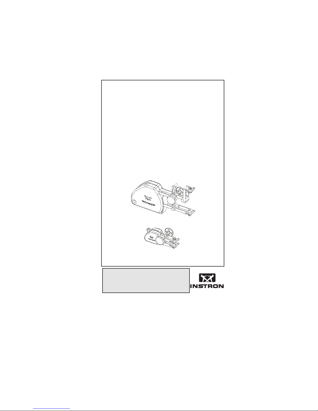
2630-100 Series Clip-On
Extensometers
Operator’s Guide
Page 2

PROPRIETARY RIGHTS NOTICE
This document and the information that it contains are
the property of Instron Corporation. Rights to
duplicate or otherwise copy this document and rights
to disclose the document and the information that it
contains to others and the right to use the information
contained therein may be acquired only by written
permission signed by a duly authorised officer of
Instron Corporation.
© Copyright 1997 Instron Corporation
Page 3

Preliminary Pages
Amendment Incorporation Record
AMENDMENT
NUMBER
1
2
3
4
5
6
7
8
BRIEF DESCRIPTION OF
CONTENT
Additional information
covering Phase 2 and
Phase 3 extensometers
Wire clip information
amended. Issue raised to
C, ECR35152
NAME OF
PERSON
INCORPORATING
AMENDMENT
Siân Oakes
Siân Oakes
9
10
iii M20-52630-1
Page 4

Preliminary Pages
Amendment Incorporation Record
AMENDMENT
NUMBER
11
12
13
14
15
16
17
18
BRIEF DESCRIPTION OF
CONTENT
NAME OF
PERSON
INCORPORATING
AMENDMENT
19
20
iv
Page 5

Preliminary Pages
GENERAL SAFETY PRECAUTIONS
Materials testing systems are potentially
hazardous!
Materials testing involves inherent hazards
from high forces, rapid motions and stored
energy. Youmust be aware of all moving and
operating components which are potentially
hazardous, particularly the actuator in a
servohydraulic testing system or the moving
crosshead in an electromechanical testing
system.
Always be aware of the possible hazards
involvedwhen operating and maintaining these
systems. You must not operate any materials
testing equipment unless you are thoroughly
familiar with its functions and operation.
Unfamiliarity with a materials testing system
can lead to unexpected actuator or crosshead
motion with the consequent risk of injury and
damage.
Carefully read all relevant manuals and observe
all WARNINGS and CAUTIONS. The term
WARNING is used where a hazard may lead to
injury or death. The term CAUTION is used
where a hazard may lead to damage to
equipment or to loss of data.
Ensure that the test set-up to be followed and
the actual test to be performed on materials,
assemblies or structures constitutes no hazard
to operating personnel.
Make full use of all mechanical and electronic
limits features. These are supplied for your
v M20-52630-1
Page 6

Preliminary Pages
safety to enable you to prevent movement of
the actuator piston / moving crosshead beyond
the desired regions of operation.
The following pages detail various general
warnings that you must heed at all times while
using materials testing equipment. More
specific warnings and cautions will be found in
the text whenever your attention needs to be
drawn to a potential hazard.
Your best safety precautions are to gain a
thorough understanding of the equipment by
reading your instruction manuals and to always
use good judgement.
WARNING
DISCONNECT THE ELECTRICAL
POWER SUPPLY BEFORE
REMOVING THE COVERS OF
ELECTRICAL EQUIPMENT
You must disconnect the equipment from the
electrical power supply before removing any
electrical safety covers or replacing fuses. Do
not reconnect the main power source while the
covers are removed unless you are specifically
instructed to do so in the manual. Refit covers
as soon as possible.
DISCONNECT POWER SUPPLIES
BEFORE REMOVING THE COVERS
OF ROTATING MACHINERY.
You must disconnect the equipment from all
power supplies before removing any cover
vi
Page 7

Preliminary Pages
which gives access to rotating machinery, e.g.
belts, screws or shafts. Do not reconnect any
power supply while the covers are removed
unless you are specifically instructed to do so
in the manual. If the equipment needs to be
operated to perform maintenance tasks with the
covers removed, ensure that all loose clothing,
long hair, etc. is tied back. Refit covers as soon
as possible.
WARNING
SHUT DOWN THE HYDRAULIC
POWER SUPPLY AND DISCHARGE
HYDRAULIC PRESSURE BEFORE
DISCONNECTION OF ANY
HYDRAULIC FLUID COUPLING.
Do not disconnect any hydraulic coupling
without first shutting down the hydraulic power
supply and discharging stored pressure to zero.
Tie down or otherwise secure all pressurised
hoses to prevent movement during system
operation and to prevent the hose from
whipping about in the event of a rupture.
SHUT OFF THE SUPPLY OF
COMPRESSED GAS AND
DISCHARGE RESIDUAL GAS
PRESSURE BEFORE
DISCONNECTION OF ANY
COMPRESSED GAS COUPLING.
vii M20-52630-1
Page 8

Preliminary Pages
Do not release gas connections without first
disconnecting the gas supply and discharging
any residual pressure to zero.
WARNING
USE PROTECTIVE SHIELDS OR
SCREENS IF ANY POSSIBILITY OF
A HAZARD EXISTS FROM THE
FAILURE OF A SPECIMEN,
ASSEMBLY OR STRUCTURE UNDER
TEST.
Protective shields should be used whenever a
risk of injury to operators and observers exists
from the failure of a test specimen, assembly or
structure, particularly where explosive
disintegration may occur. Due tothe wide
range of specimen materials, assemblies or
structures that may be tested using materials
testing equipment, any hazard resulting from
the failure of a test specimen, assembly or
structure is entirely the responsibility of the
owner and user of the equipment.
PROTECT ELECTRICAL CABLES
FROM DAMAGE AND
INADVERTENT DISCONNECTION.
The sudden loss of controlling and feedback
signals which can result from a disconnected or
damaged cable causes an open loop condition
which may drive the actuator of crosshead
rapidly to its extremes of motion. All electrical
cables, particularly transducer cables, must be
viii
Page 9

Preliminary Pages
protected from damage. Never route cables
across the floor without protection, nor suspend
cables overhead under excessive strain. Use
paddings to avoid chafing where cables are
routed around corners or through wall openings.
WARNING
WEAR PROTECTIVE CLOTHING
WHEN HANDLING EQUIPMENT AT
EXTREMES OF TEMPERATURE.
Materials testing is often carried out at
non-ambient temperatures using ovens,
furnaces or cryogenic chambers. Extreme
temperature means an operating temperature
exceeding +60 °C (140 °F) or below 0 °C
(32 °F). Youmust use protectiveclothing, such
as gloves, when handling equipment at these
temperatures. A warning notice concerning low
or high temperature operation must be
displayed whenever temperature control
equipment is in use. You should note that the
hazard from extreme temperature can extend
beyond the immediate area of the test.
TAKE CARE WHEN INSTALLING OR
REMOVING A SPECIMEN,
ASSEMBLY OR STRUCTURE.
Installation or removal of a specimen, assembly
of structure involves working inside the hazard
area between the grips or fixtures. Keep clear
of the jaws of a grip or fixture at all times.
Keep clear of the hazard area between the grips
or fixtures during actuator or crosshead
ix M20-52630-1
Page 10

Preliminary Pages
movement. Ensure that all actuator or
crosshead movements necessary for installation
or removal are slow and, where possible, at a
low force setting.
WARNING
BEFORE THE EXTENSOMETER IS
USED IN STRAIN CONTROL,
CHECK THE FOLLOWING:
1. Ensure that the extensometer
is securely attached to the
specimen.
2. Ensure that the extensometer
is calibrated.
3. Set the Load, Position and
Strain limits.
4. Ensure that the testing
machine loop-shaping
parameters are set correctly.
BEFORE REMOVING THE
EXTENSOMETER FROM THE
SPECIMEN AT ANY TIME, ENSURE
THAT THE MACHINE IS NOT IN
STRAIN CONTROL!
x
Page 11

Preliminary Pages
xi M20-52630-1
Page 12

Preliminary Pages
Table Of Contents
Chapter Page
INTRODUCTION 1-1
GENERAL 1-1
BASIC FEATURES 1-2
EQUIPMENT SUPPLIED 1-4
OPTIONAL ACCESSORIES& SPARES 1-4
SPECIFICATION 2-1
ENVIRONMENTAL 2-1
OPERATION 3-1
GAUGE LENGTH SETTING 3-1
SPECIMEN ATTACHMENT 3-3
Wire Clip 3-3
Variable Pressure Specimen
Clamp 3-5
Elastic Bands or O-Rings 3-7
Fitting to the Specimen using
Both Hands 3-8
Fitting to the Specimen using
One Hand 3-9
CABLE CLEAT AND EXTENSOMETER
HOLDER 3-10
xi M20-52630-1
Page 13

Preliminary Pages
KNIFE EDGE CHANGING 3-12
Specimen Centering Stops 3-13
IMPORTANT SAFETY NOTE 3-14
CALIBRATION 3-15
Automatic Electrical
Calibration 3-15
Manual Electrical
Calibration 3-16
Manual Mechanical
Calibration 3-18
VERIFICATION 3-19
APPENDIX A
CLIP SIZES A-1
CLIPS FOR ROUND SPECIMENS A-2
CLIPS FOR RECTANGULAR
SPECIMENS A-4
Notes A-6
xii
Page 14

Preliminary Pages
LIST OF ILLUSTRATIONS
Figure Page
1-1. Case Layout 1-5
3-1. Gauge Length Setting with the
cone-latch released 3-1
3-2. Gauge Length Setting with the
cone-latch engaged
(gauge length set) 3-2
3-3. Insertion of Clips 3-4
3-4. Wire clips in use 3-4
3-5. Specimen attachment using the
optional Specimen Clamps
and Pivot Knife Edges 3-6
3-6. Specimen attachment using
elastic bands 3-7
3-7. Two-handed Installation 3-8
3-8. Single-handed Installation 3-9
3-9. Extensometer suspended from
cleat post — T-slot machines 3-10
3-10. Extensometer suspended from
cleat post — steel covered
machines 3-11
3-11. Knife Edge Replacement 3-12
xiii M20-52630-1
Page 15

Preliminary Pages
3-12. Specimen Stops 3-13
3-13. Extensometer mounted on an
optional calibration fixture
(Cat. No. 2602-017) 3-17
List of Tables
Table Page
1. Extensometer Gauge Lengths
and Travel 2-1
2. General Specification 2-3
3. Machine Compatibility 2-5
4. Extensometer Physical
Compatibility with 3119 Series
Temperature Chambers 2-8
xiv
Page 16

GENERAL
The 2630-100 series extensometers convert
the mechanical displacement of a strained
test specimen into an electrical signal. When
used with the current range of Instron
testing machines, each extensometer is
automatically recognised, and is able to be
calibrated at the touch of a button.
The displacement is transmitted by a light
rigid frame to strain gauges bonded to a
flexural element. The gauges are arranged in
a fully active four-arm Wheatstone Bridge
circuit.
The 2630-100 series of extensometers
includes different gauge lengths/strain range
options to suit a wide range of specimen
characteristics.
Robust construction provides accuracy and
reliability.As with all measuring
instruments, rough handling, contamination
with dirt and moisture effect calibration and
shorten the life of the instrument.
INTRODUCTION
INTRODUCTION
The extensometer is supplied in a
foam-lined presentation case, dimensions
350 mm (13.8 in.) long, 260 mm (10.2 in.)
wide and 85 mm (3.3 in.) deep. The
shipping weight is 0.9 kg (2 lbs).
When not in use, the extensometer should
be stored in the presentation case.
1-1 M20-52630-1
Page 17

INTRODUCTION
BASIC FEATURES
• Ergonomic, lightweight,
cross-braced design with overload
protection.
• Easy attachment and release from
the specimen facilitate
single-handed operation.
• Simple, cone latch gauge-length
setting method with automatic
disengagement.
• Precise, fixed gauge-lengths with
automatic recognition and
calibration capability.
• Available in metric and U.S.
Customary versions to meet
ISO 9513 and ASTM E83
standards of accuracy.
• Low operating-force arms with
single-bevel, interchangeable knife
edges.
• Suitable for a wide range of
specimen materials, geometry and
size with a choice of attachment
methods.
• Combined cable cleat and
extensometer holder with
provision for retaining cord
attachment to the extensometer.
• High impact plastic storage case
with a contour moulded insert,
securely retains the extensometer
1-2
Page 18

INTRODUCTION
and accessory parts together with
its Calibration Certificate and
comprehensive operating manual.
1-3 M20-52630-1
Page 19

INTRODUCTION
EQUIPMENT SUPPLIED
Refer to Figure 1-1.
1 Extensometer
2 Cable cleat and extensometer holder
3 Allen key
4 11 pairs of wire clips
5 Specimen centering stops
6 Operator’s guide
7 Calibration certificate
8 Foam lined presentation case
OPTIONAL ACCESSORIES &
SPARES
1 Variable pressure specimen clamps: see page 3-5.
2 Replacement knife edges, one pair, straight
profile. All purpose use on round and rectangular
cross section specimens. Cat No. 2601-077.
3 Replacement knife edges, one pair. Three point
contact for flat specimens that are not truly flat.
Cat No. 2601-078.
4 Replacement knife edges one pair. Radiused edge
for flat specimens that are not truly flat.
Cat No. 2601-079.
5 Digital Readout Extensometer Calibrator for manual
span setting. Cat No. 2602-017.
7 Wire clips (see Appendix A).
8 O-Rings, internal diameter 11 mm unstretched.
(Instron Part No. T1351-1034).
1-4
Page 20

INTRODUCTION
CASE
EXTENSOMETER
OPERATOR’S GUIDE
CABLE CLEAT AND
EXTENSOMETER HOLDER
ALLEN
KEY
SPECIMEN
STOPS
CLIPS FOR ROUND
CLIPS FOR RECTANGULAR
SPECIMENS
SPECIMENS
Figure 1-1. Case Layout
1-5 M20-52630-1
Page 21

SPECIFICATION
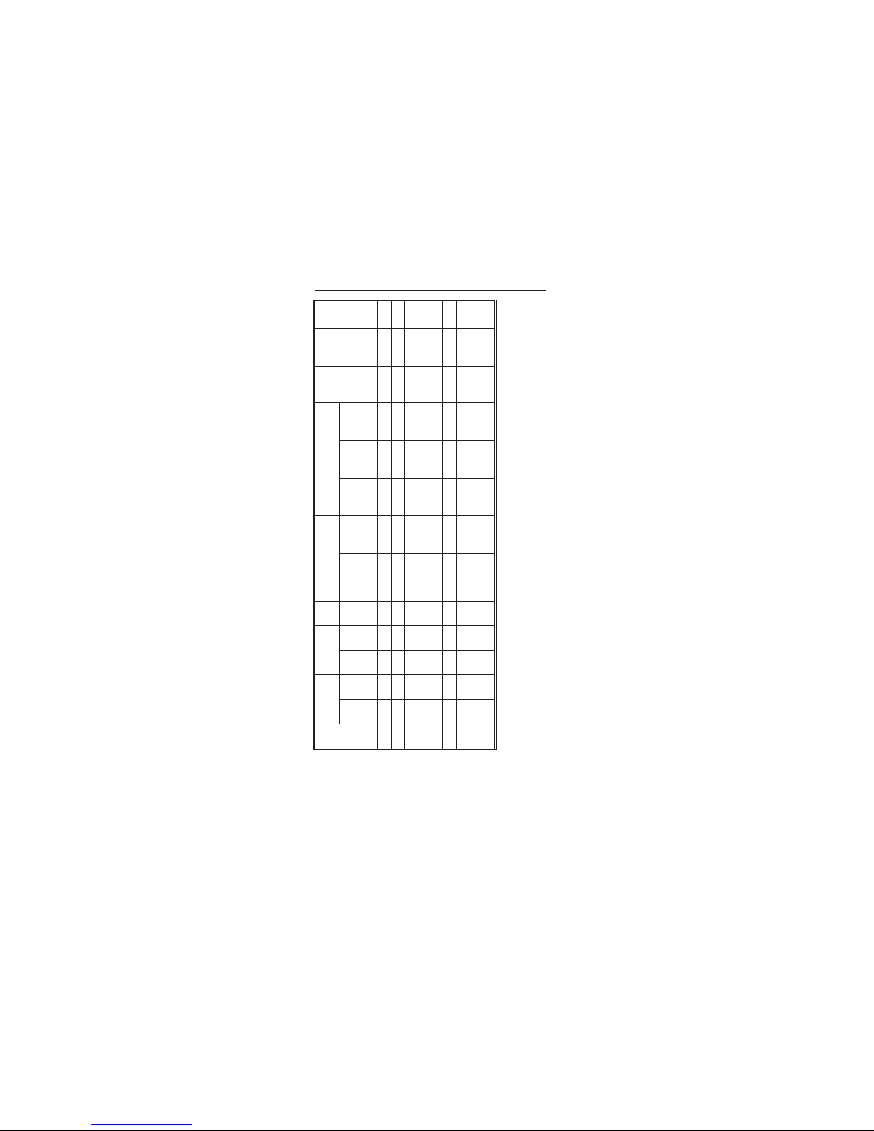
Table 1. Extensometer Gauge Lengths and Travel
SPECIFICATION
G.L
Strain % Travel mm (in.)
mm
(in.)
+ve -ve +ve -ve 2630- Class 0.5(B-2) Class 1 (C) Length Width Height
8 50 50 4 4 120 0, +50 30, +50 67 (2.64) 39 (1.5) 25 (1) 20(0.04) 27 (0.06) Dual
2-1
(0.3) 50 50 (0.15) (0.15) 121 0, +50 30, +50 67 (2.64) 39 (1.5) 25 (1) 20 (0.04) 27 (0.06) Dual
10 10 10 1 1 101 -10,+10 67 (2.6) 39 (1.5) 25 (1) 160 (0.35) 27 (0.06) Single
10 50 50 5 5 102 0, +50 30, +50 67 (2.64) 39 (1.5) 25 (1) 20 (0.04) 27 (0.06) Single
(0.5) 10 10 (0.05) (0.05) 103 -10, +10 67 (2.64) 39 (1.5) 25 (1) 170 (0.37) 27 (0.06) Single
(0.5) 50 50 (0.25) (0.25) 104 0, +50 30, +50 67 (2.64) 39 (1.5) 25 (1) 20 (0.4) 27 (0.06) Single
25 10 10 2.5 2.5 105 -10, +10 100 (4) 39 (1.5) 52 (2) 55 (0.12) 56 (0.12) Single
25 50 10 12.5 2.5 106 0, +50 115(4.5) 39 (1.5) 58 (2.3) 75 (0.17) 58 (0.13) Single
25 100 10 25 2.5 107 0, +70 0, +100 132 (5.2) 39 (1.5) 69 (2.7) 45(0.1) 60 (0.13) Single
(1) 10 10 (0.1) (0.1) 108 -10, +10 100 (4) 39 (1.5) 52 (2) 56 (0.12) 56 (0.12) Single
Cat.
*Class I SO9513 (ASTME83)
No.
Strain%
Overall Dimensions
mm (in.)
Operating
Force
g (lbs)
+Weight
g (lbs)
Code
Type
Page 22
G.L
mm
(in.)
Strain % Travel mm (in.)
Cat.
No.
*Class ISO 9513 (ASTM E83)
Strain%
Overall Dimensions
mm (in.)
Operating
Force
g (lbs)
+Weight
g (lbs)
Code
Type
+ve -ve +ve -ve 2630- Class 0.5 (B-2) Class 1 (C) Length Width Height
(1) 50 10 (0.5) (0.1) 109 0, +50 115 (4.5) 39 (1.5) 58 (2.3) 75 (0.17) 58 (0.13) Single
(1) 100 10 (1) (0.1) 110 0, +70 0, +100 132 (5.2) 39 (1.5) 69 (2.7) 45 (0.1) 60 (0.13) Single
50 10 10 5 5 111 -10, +10 100 (4) 39(1.5) 72 (2.8) 45 (0.1) 60 (0.13) Single
50 50 5 25 2.5 112 0, +35 0, +50 132 (3.2) 39 (1.5) 72 (2.8) 45 (0.1) 60 (0.13) Single
50 100 10 50 5 113 0, +70 0, +100 181 (7.1) 39 (1.5) 72 (2.8) 37(0.08) 70 (0.15) Dual
(2) 10 10 (0.2) (0.2) 114 -10, +10 100 (4) 39 (1.5) 72 (2.8) 45 (0.1) 60 (0.13) Single
(2) 50 5 (1) (0.1) 115 0, +35 0,+50 132 (5.2) 39 (1.5) 72 (2.8) 45 (0.1) 60 (0.13) Single
(2) 100 10 (2) (0.2) 116 0, +70 0, +100 181 (7.1) 39 (1.5) 72 (2.8) 37 (0.08) 70 (0.15) Dual
80 10 1 8 0.8 117 0, +10 116 (4.6) 39 (1.5) 101(4) 60 (0.13) 60 (0.13) Dual
80 50 5 40 4 118 0, +35 0, +50 181 (7.1) 39 (1.5) 101(4) 45(0.1) 70 (0.15) Dual
100 50 5 50 5 119 0, +35 0, +50 181 (7.1) 39 (1.5) 121 (4.8) 37 (0.08) 70 (0.15) Dual
*:
+
:
When calibrated using appropriate calibration apparatus these extensometers are guaran-
teed to meet the stated classification. Outside these stated ranges the extensometers in
compressive mode generally perform to ISO 1.0 or ASTM C classification.
Weightexcludes cable and connector.
2-2 M20-52630-1
SPECIFICATION
Page 23

Table 2. General Specification
SPECIFICATION
Creep (3 mins - 5 secs)
Repeatability <0.1 % of FS
Hysteresis <0.3 % of FS
Balance
Excitation 1 to 5 Vrms, d.c. to 5 kHz
2-3
Sensitivity (full scale) 2.5 +1 % -3 % mV/V
Overtravel limit Mechanical stops
Electrical calibration accuracy
Bridge resistance (nominal) 350
Gauge length accuracy
Temperature range -100 to +200 °C
Temperature effect on zero
<± 0.15
<± 2.5
± 0.06
± 0.5
± 0.01
% of FS
% of FS
% of FS
Ω
% of GL
% /°C
Page 24

Effect of Temperature on
sensitivity
-0.006, 20 to 100 °C (typical)
-0.008, 100 to 150 °C (typical)
-0.01, 150 to 200 °C (typical)
% /°C
Method of attachment to
Specimen
11 types of wire clips.
Elastic bands (not supplied).
Optional specimen clamps (refer to page 3-5).
Immersibility
Non-conductive / non-corrosive fluids, i.e.
acetone, mineral and silicone oils, alcohol, etc.
Gauge length setting Cone latch with automatic release
Round specimen sizes <15, (0.6 in.) and 20 (0.8 in.) mm
Rectangular specimen sizes
Width <40 (1.6 in.)
Thickness <15, (0.6 in.)
mm
Knife edge gripping force
300 to 600 (0.66 to 1.32 lbs), subject to the correct
selection of clips
grams
Maximum width of specimen
with specimen stops fitted
18 mm (0.71 in.)
NOTE FS — Full Scale. All values relate to a temperature of 22 °C unless otherwise stated.
2-4 M20-52630-1
SPECIFICATION
Page 25

Table 3. Machine Compatibility
The extensometer connector plugs contain codes which are used by the testing machine to define gauge length, travel
and calibration points. The extensometers are fitted with either a single code or dual codes, as shown in Tabl e1.
SPECIFICATION
Machine Series
Automatic
Electrical Calibration
Manual Electrical
Calibration
Manual
Mechanical
Calibration
Comments
Via user-defined
2-5
8000 All Not available All
transducer setup
using first code
only.
8500 prior to V21 Single code only Single code only Single code only
8500 V21
8500 Plus All All All
All except 2630-119,
120, 121
All except 2630-119,
120, 121
All except 2630-119,
120, 121
Versions may be
identified via the
front panel or
MDC board label.
Page 26

Machine Series
Automatic
Electrical Calibration
Manual Electrical
Calibration
Manual
Mechanical
Calibration
Comments
6000 All Not available All
Via user-defined
transducer setup
using first code
only.
4500 prior to
V2.25MS04
Single code only All All
Versionmay be
identified via the
Master board
label.
4500 post V2.25MS04
All except 2630-120,
121
All All
4500 Post V2.25MS05
or later
All All All
4200/4300 CPU card
with PROMs prior to
A474-717, 718, 719, 720
Single code only
All All
Check CPU card.
4200/4300 CPU card
with PROMs
A474-717, 718, 719, 720
All except 2630-120,
121
All All
2-6 M20-52630-1
SPECIFICATION
Page 27

Machine Series
Automatic
Electrical Calibration
Manual Electrical
Calibration
Manual
Mechanical
Calibration
Comments
4200/4300 CPU card
with PROMS A474-736,
737, 738, 739 or later
All All All
Check CPU card.
2180/2160 Not available All All
1100 No All All
4400
All except
2630-120,121
All All
4400 PROM A474-740
or later
All All All
5500 Pre-Dec 93
All except 2630-120,
121
All All
5500 Post-Dec 93 All All All
2-7
SPECIFICATION
Page 28

SPECIFICATION
ENVIRONMENTAL
The extensometer’s simple and easy
attachment method make it ideal for use
in a temperature chamber.
The extensometer’s temperature
capability is stated in Table 2.
High relative humidity may alter
calibration and it is advisable to confirm
the calibration using a suitable
calibration fixture at the test condition.
CAUTION:
Contamination by
condensation, electrically
conducting fluids, dirt or
corrosive substances may
damage the extensometer.
Table 4.
Extensometer Physical Compatibility with
3119 Series TemperatureChambers
Chamber
Cat. No.
3119-005 All except 2630-113, 116, 118 and 119
3119-006 All except 2630-113, 116, 118 and 119
3119-007 All
3119-008 All
3119-009 All except 2630-113, 116, 118 and 119
Suitable Extensometers
2-8 M20-52630-1
Page 29
OPERATION
OPERATION
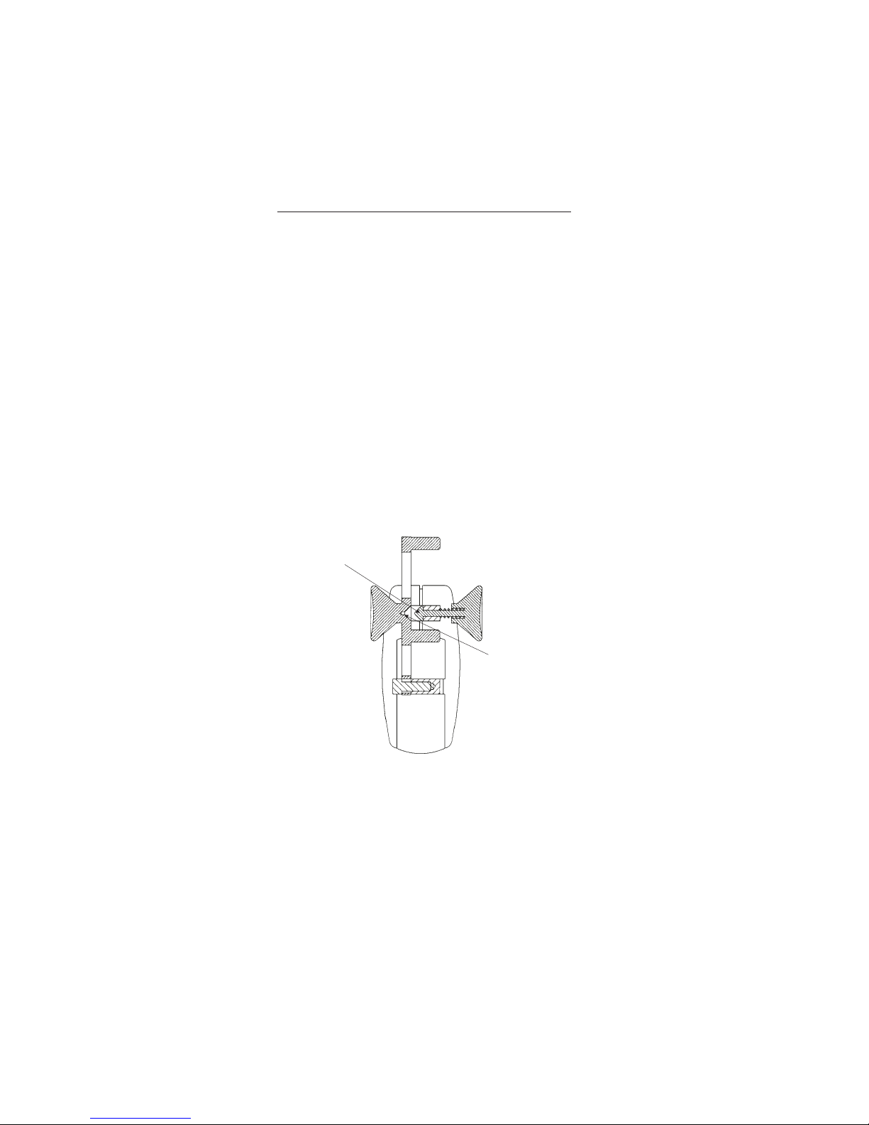
GAUGE LENGTH SETTING
Before strain can be accurately measured
the extensometer arms must be spaced to
set the knife edges at gauge length. The
extensometer features an integral cone
latch arm locating system.
To set gauge length press the two round
buttons with index finger and thumb of
either left or right hand. Ensure the cone
locates in the cone-seat. The extensometer
knife edges are now held at the correct
gauge length. The extensometer is ready
for attaching to a test specimen (refer to
Figures 3-1 and 3-2).
CONE PIN
CONE SEAT
Figure 3-1. Gauge Length Setting
with the cone-latch released
3-1
Page 30

OPERATION
Verification of gauge length may be
confirmed by engaging the gauge length
cone latch and checking the distance
between the knife edges using either
callipers or a slip gauge.
Figure 3-2. Gauge Length Setting
with the cone-latch engaged
(gauge length set)
3-2 M20-52630-1
Page 31

OPERATION
SPECIMEN ATTACHMENT
For accurate results, effective attachment
of the extensometer to the specimen is
essential. Test results may be altered if the
knife edges press too firmly into the
specimen. A sign of excessive knife edge
pressure is breaking of the specimen at the
knife edge point of contact. At the other
extreme, with low knife edge pressure,
slippage may occur. This can be identified
from a stress v strain graph by a rapid
change in strain for a small change in
stress. If a test is to involve strains greater
than 10%, a higher clamping force may be
required.
A number of different attachment
methods are available offering the
flexibility to suit a wide range of testing
conditions. Care during attachment should
avoid any difficulties and permit the
optimum knife edge pressure to be
achieved.
Knife edges should be replaced if blunt,
as described on page 3-12.
Wire Clip
Clips are available in two profiles to
accommodate round and rectangular
specimens. It is important for good results
to select the clip that best suits the
specimen. Appendix A gives full size
scale diagrams of the available clips with
information on the optimum working
range for each clip. The clips mount into
the extensometer arms from either side,
3-3
Page 32

OPERATION
using the technique shown in Figure
3-3. Figure 3-4 shows the wire clip in
operation holding the extensometer to a
typical specimen.
Once the wire clip is selected and a test
specimen is correctly installed in the
testing machine grips the extensometer
can be attached.
Figure 3-3. Insertion of Clips
Figure 3-4. Wire clips in use
3-4 M20-52630-1
Page 33

OPERATION
Variable Pressure Specimen Clamp
If preferred, the instrument may be
changed to use variable pressure specimen
clamps as supplied on earlier 2630 series
instruments. This requires optional notch
pivot knife edges to permit the use of
specimen clamps.
Specimen clamps are an optional extra
and can be ordered from Instron using the
following Catalogue Numbers:
Cat No. 2601-081, specimen clamp and
knife edges — Small, minimum gauge
length 10 mm. Accommodates round
specimens 1 to 9 mm in diameter or flat
specimens to 9 mm wide and 1 to 10 mm
thick.
Cat No. 2601-082, specimen clamp and
knife edges — Medium, minimum gauge
length 25 mm. Accommodates round
specimens 1 to 15 mm in diameter in diameter or flat specimens to 14 mm wide
and 1 to 18 mm thick.
Cat No. 2601-083, specimen clamp and
knife edges — Large, minimum gauge
length 25 mm. Accommodates round
specimens 1 to 10 mm in diameter or flat
specimens to 25 mm wide and 1 to 10 mm
thick.
To fit the Extensometer to the Specimen
Hold the extensometer with the Gauge
Length cone-latch engaged and position
the knife edges against the test specimen.
Holding a specimen clamp, straddle the
3-5
Page 34

OPERATION
specimen above the knife edges of the
extensometer. Press the clamp against
the specimen to compress the spring
loaded plunger and hook the specimen
clamp on the knife edges. Ensure that
the knife edge seats properly in the
specimen clamp notch pivot. Repeat the
same operation on the lower specimen
clamp.
When testing round specimens, align the
“V” groove of the spring-loaded plunger
before straddling the specimen.
Note that the notch pivot slots in the
specimen clamp should always point
away from the gauge length, as shown
below.
NOTCH PIVOT
NOTCH PIVOT SLOTS
POINTING OUTWARDS FROM
THE GAUGE LENGTH
VARIABLE PRESSURE
SPECIMEN CLAMP
PRESSURE ADJUSTER RING
Figure 3-5. Specimen attachment
using the optional Specimen Clamps
and Pivot Knife Edges
3-6 M20-52630-1
Page 35
OPERATION
Elastic Bands or O-Rings
Hooks for elastic bands or O-rings are an
integral part of the knife edges, although
elastic bands and O-rings are not supplied
with the extensometer. Refer to page 1-4
for O-ring details.
Hold the extensometer with the gauge
length cone latch engaged and position
the knife edges on the test specimen.
Stretch good quality elastic bands or
O-rings around the specimen and loop the
ends over the two knife edge hooks, as
shown in Figure 3-6.
Figure 3-6. Specimen attachment
using elastic bands
3-7
Page 36

OPERATION
Fitting to the Specimen using Both
Hands
When testing soft or delicate materials,
two-handed installation reduces the
possibility of marking the specimen.
Hold the extensometer with either hand
and engage the gauge length cone-latch.
Using the other hand open the wire clips
to clear the specimen, as shown in
Figure 3-7. Position the extensometer in
line with the specimen and gradually
release the clips. Once the extensometer
is attached to the specimen the gauge
length cone-latch can be released. If the
extensometer is not held firmly onto the
specimen select a smaller clip.
PRESS TO SET
GAUGE LENGTH
CLIP PRONG
Figure 3-7. Two-handed Installation
3-8 M20-52630-1
Page 37

OPERATION
Fitting to the Specimen using One Hand
Single handed installation is useful for
working in temperature cabinets where
access is limited.
Hold the extensometer with either hand
and engage the gauge length cone-latch.
Hook the wire clip prongs behind the
specimen as shown in Figure 3-8. Pull the
extensometer to open the wire clips to
clear the specimen. Slide the clip against
the specimen bringing the extensometer in
line with the specimen and gradually
release the clips so the knife edges gently
touch the specimen. Do not slide the knife
edge against the specimen as the
specimen may be marked or the knife
edge blunted. Once the extensometer is
attached to the specimen, release the
gauge length cone-latch. If the
extensometer is not held firmly onto the
specimen select a smaller clip.
PRESS TO SET
GAUGE LENGTH
Figure 3-8. Single-handed Installation
CLIP PRONG
3-9
Page 38

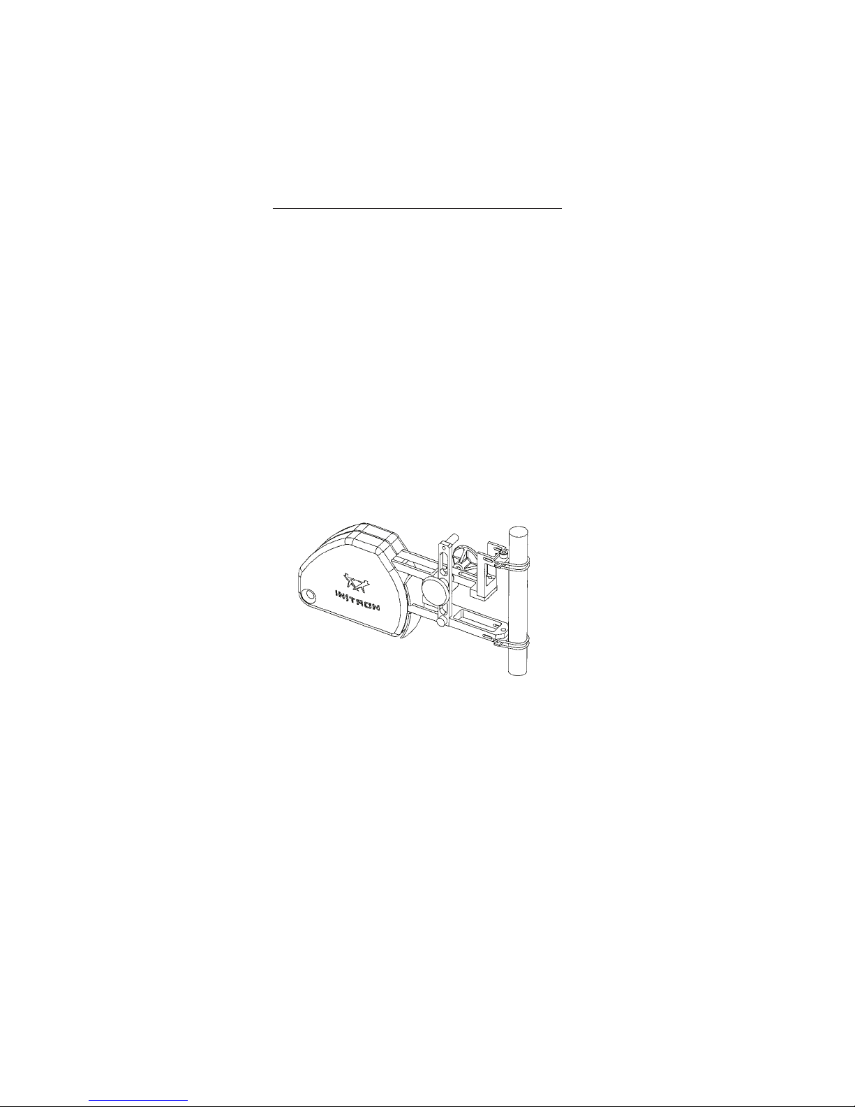
CABLE CLEAT AND
EXTENSOMETER HOLDER
A combined cable cleat and
extensometer holder is provided, and is
shown in Figures 3-9 and 3-10.
The magnetic base of the cleat can be
attached to steel parts of the testing
machine e.g. the column covers. For “T”
slot machines with aluminium column
covers the special keeper assembly will
slide into the “T” slot and then the cleat
will attach to the keeper.
The slot in the base of the cleat is used
to support the extensometer cable. The
cleat should be positioned to reduce the
effects of cable tension on the
extensometer.
OPERATION
KEEPER NUT
SLIDE INTO
T-SLOT
Figure 3-9. Extensometer suspended
from cleat post — T-slot machines
3-10 M20-52630-1
Page 39

OPERATION
ATTACH TO
STEEL
SURFACE
SLOT FOR
CABLE
Figure 3-10. Extensometer suspended
from cleat post — steel covered
machines
When the extensometer is not in use but is
still required to be connected to the testing
machine, it may be secured to a cleat post
using the hole provided in the
extensometer cover.
Ensure the cleat is returned to the
presentation case, with the magnet
attached to the keeper plate when not in
use.
3-11
Page 40

KNIFE EDGE CHANGING
Refer to Figure 3-11 below. Loosen the
socket head cap screw using the
supplied allen key.
Position replacement knife edge with
the bevel side of the knife edge furthest
from the cut-out in the extensometer
arms. Secure with socket head cap
screw ensuring alignment faces of the
knife edge and extensometer touch.
SOCKET HEAD CAP
SCREW
ALIGNMENT FACES
OPERATION
KNIFE EDGE
BEVELLED
EDGE
Figure 3-11. Knife Edge Replacement
3-12 M20-52630-1
Page 41

OPERATION
SPECIMEN CENTERING STOPS
Precise alignment of the extensometer is
necessary to ensure the correct
measurement of strain in a specimen and
to enable rapid, precise attachment to the
specimen. To achieve this a pair of
optional stops are supplied to assist with
aligning the extensometer relative to the
specimen. Graduations are marked on the
surface of the stops to allow equal setting.
The installation of a specimen stop is
shown below in Figure 3-12.
SOCKET HEAD
CAP SCREW
EXTENSOMETER
ARM
SPECIMEN STOP
Figure 3-12. Specimen Stops
3-13
Page 42

OPERATION
IMPORTANT SAFETY NOTE
WARNING
BEFORE THE EXTENSOMETER
IS USED IN STRAIN
CONTROL, CHECK THE
FOLLOWING:
1. Ensure that the
extensometer is securely
attached to the specimen.
2. Ensure that the
extensometer is calibrated.
3. Set the Load, Position
and Strain limits.
4. Ensure that the testing
machine loop-shaping
parameters are set
correctly.
BEFORE REMOVING THE
EXTENSOMETER FROM THE
SPECIMEN AT ANY TIME,
ENSURE THAT THE MACHINE
IS NOT IN STRAIN CONTROL.
3-14 M20-52630-1
Page 43

OPERATION
CALIBRATION
The extensometer and machine
conditioning electronics must be
calibrated before use. Three parameters
must be defined: full scale, calibration
point and gauge length.
Three methods of calibration are possible:
Automatic Electrical Calibration
This is the normal method of calibration
for current Instron testing machines. The
extensometer is self-identifying via its
code resistors. These are interrogated by
the testing machine which has the
calibration parameters stored within its
memory. If the extensometer is to be used
on an older Instron machine check
compatibility with automatic calibration,
refer to page 2-5.
To operate the automatic electrical
calibration, refer to the operating
instructions or user’s guide supplied with
the testing machine.
Note: Ensure that the
extensometer is set at
gauge length, and is
correctly attached to the
test specimen. Refer to
pages 3-1 to 3-8.
3-15
Page 44

OPERATION
Manual Electrical Calibration
This method can be used if your testing
machine is unable to use the
self-identifying feature or if you wish to
modify the calibration parameters.
To operate manual electrical calibration
refer to the operating instructions or
user’s guide supplied with the testing
machine.
Note: Ensure that the exten-
someter is set at gauge
length, and is correctly attached to the test specimen. Refer to pages 3-1
to 3-8.
3-16 M20-52630-1
Page 45

OPERATION
Figure 3-13. Extensometer mounted on
an optional calibration fixture
(Cat. No. 2602-017)
3-17
Page 46

OPERATION
Manual Mechanical Calibration
This method must be used on older
testing machines that are unable to
perform any other type of calibration. It
is also a way of confirming the electrical
calibration.
A calibration fixture is required for
manual mechanical calibration (refer to
page 1-4 — Optional Accessories and
Spares). The fixture consists of a digital
micrometer head, mounted on a stand
frame, with two knurled collets for
holding various calibrator spindles
corresponding to types and sizes of
specimens to be tested. It enables the
extensometer to be exercised over its
mechanical displacement range and the
span to be checked or set.
Note: Ensure that the exten-
someter is set at gauge
length, and is correctly attached to the Calibrator.
Refer to pages 3-1 to 3-8.
3-18 M20-52630-1
Page 47

OPERATION
VERIFICATION
The achievable ISO or ASTM
classification is given in Table 1 on pages
2-1 and 2-2. Certification of the strain
measurement system which includes the
extensometer, conditioning electronics
and readout to the international standards
should be arranged through accredited
calibration services. Your local Instron
area office will be able to arrange
verification.
NOTE It is advisable to check the
accuracy of the
automatic/manual
electrical calibration at
least once per year.
3-19
Page 48

CLIP SIZES
APPENDIX A
CLIP SIZES
Use the full-scale diagrams on the following
pages to identify the various clips supplied
with the extensometer.
Appendix A A-1 M20-52630-1
Page 49

CLIP SIZES
CLIPS FOR ROUND SPECIMENS
(Supplied in pairs)
T1696-1390
Ø0 to 3 mm
Ø 0 to 0.12 in.
T1696-1391
Ø3 to 6 mm
Ø 0.12 to 0.24 in.
Appendix A A-2
T1696-1392
Ø6 to 9 mm
Ø 0.24 to 0.35 in.
Page 50

CLIP SIZES
T1696-1393
Ø9 to 12 mm
Ø0.35 to 0.47 in.
T1696-1394
Ø12 to 15 mm
Ø0.47 to 0.59 in.
Appendix A A-3 M20-52630-1
T1696-1388
Ø20 mm
Ø0.79 in.
Page 51

CLIP SIZES
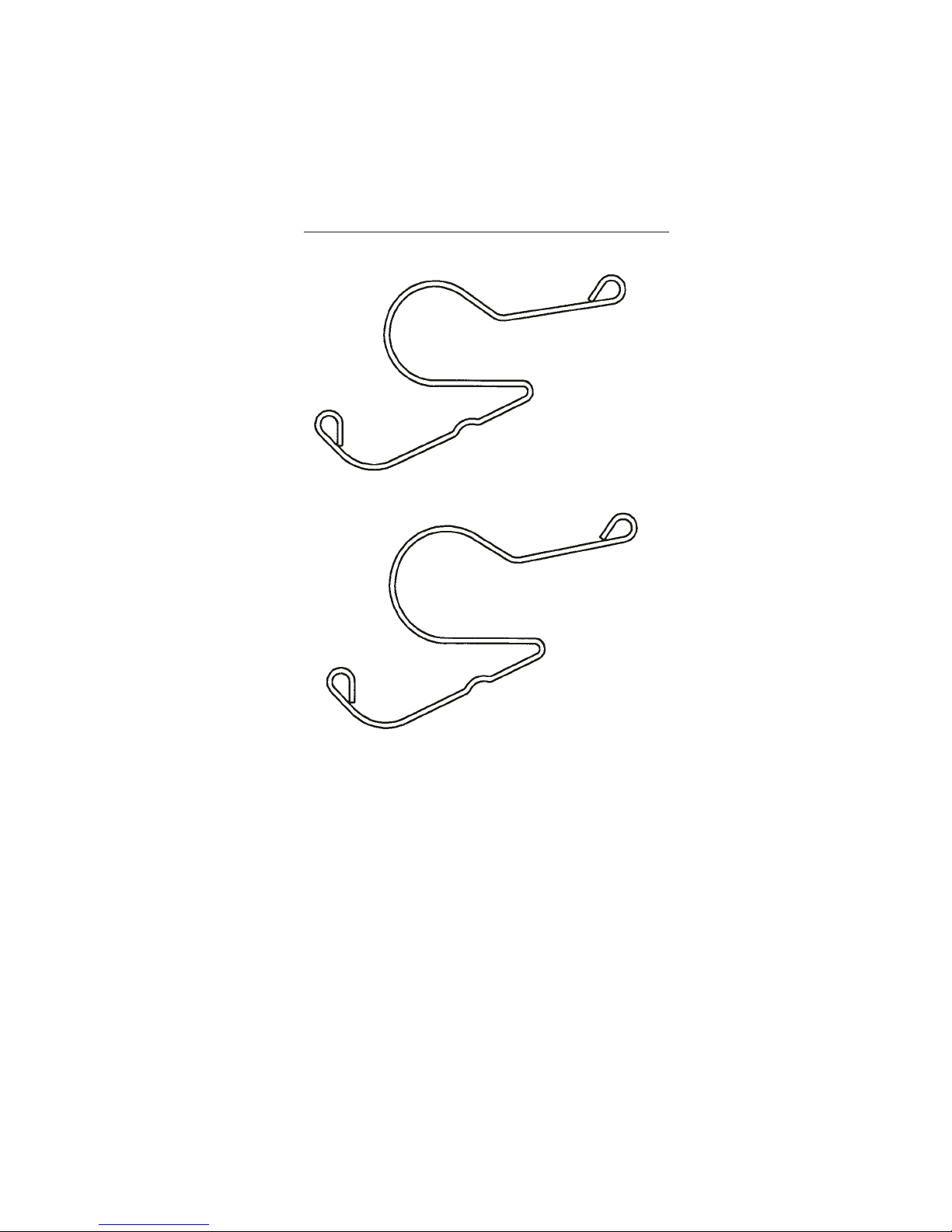
CLIPS FOR RECTANGULAR
SPECIMENS
(Supplied in pairs)
T1696-1395
SQR 0 to 3 mm
SQR 0 to 0.12 in.
T1696-1396
SQR 3 to 6 mm
SQR 0.12 to 0.24 in.
Appendix A A-4
T1696-1397
SQR 6 to 9 mm
SQR 0.24 to 0.35 in.
Page 52
CLIP SIZES
T1696-1398
SQR 9 to 12 mm
SQR 0.35 to 0.47 in.
T1696-1399
SQR 12 to 15 mm
SQR 0.47 to 0.59 in.
Appendix A A-5 M20-52630-1
Page 53

CLIP SIZES
NOTES
Appendix A A-6
 Loading...