

Step-by-Step Guide to Using Your
In-Step Mobility Products Corp.
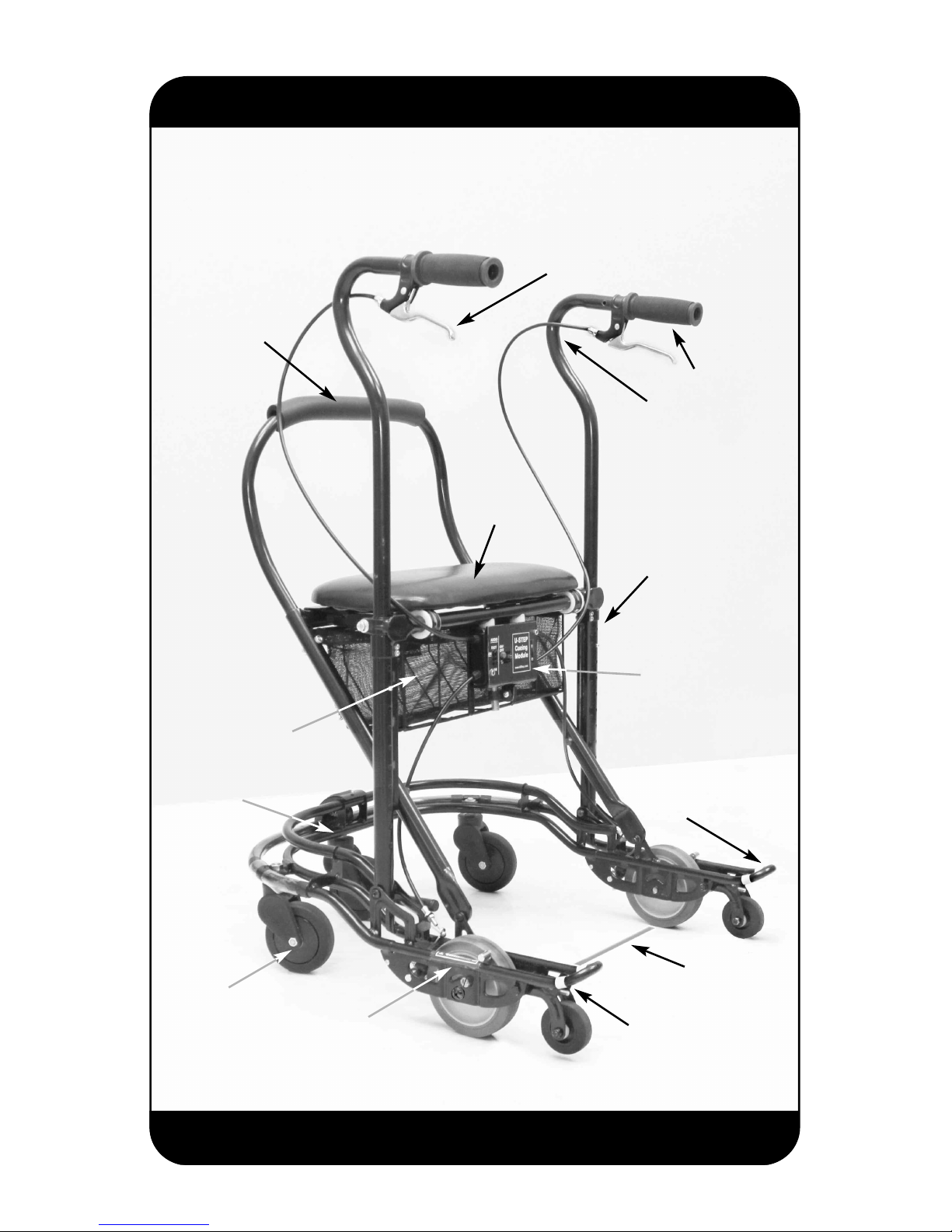
U-Step II Walking Stabilizer
4-inch
non-marking
casters
Padded
seat
Tension
control
Height
adjustable
Adjustable
backrest
Spring-loaded
front wheel
Place to step for
going up curbs
Glow-in-the-Dark
tabs
Laser module
(Optional)
Laser
projected
r
ed line –
optional
Ergonomically
positioned
handlebars
Comfort grips
Hand brake
Removable
basket

— 2 —
CONTENTS:
A. Assembly Instructions
B. Braking
C. Tension Control Adjustment
D. Sitting Down
E. Walking Over Obstacles
F. Transporting
G. Setup After Transporting
H. Accessories
1. Alternative Brake Accessory
2. Laser & Sound Cueing Module
3. Replacing the Cueing Module Batteries
4. Optional Weights
I. Maintenance
J. Warranty Information
Guide for Setting Up & Using Your U-Step II

1) After opening the box, cut the plastic ties that secured the
U-Step II in transit.
2) Attach the basket to
the U-Step II. The back
of the basket has a
mounting plate that
connects to the flat
hooks on the back of the
junction.
(See Right)
Position the mounting
plate in front of the flat
hooks and slide the basket down until the
mounting plate engages
in the flat hooks.
(Below)
— 3 —
A. Assembly Instructions
Flat black hooks
3) Lift up on the tube at the top near the seat so that the seat
becomes horizontal with the ground. (See above) Press the seat
down until it snaps into place. (Below)
4) Install the left and
the right handlebars.
(See top of page 5)
If you have any doubt
which is the left and
right handlebar, look
at the junction box
below the seat and
you can see the left
handle bar cable is
connected into the
left side and visa
versa for the right.
— 4 —

You will need to push in the
height adjustment button to
slide the handle bar into the
lower height adjustment
tube.
(Right)
Also, when you insert the
handlebars make sure that
the cables are routed to the
inside of the handlebars,
rather than the outside.
(Below)
5) Adjusting the handlebars to
the proper height. Generally,
the handlebars are adjusted so
that the handles are 2-3 inches
above your palm when your arm
rests at your side.
— 5 —
Junction Box
Right Handlebar
Left Handlebar

6) Using the wrench
provided, tighten
the height adjustment bolt so that the
handle bars do not
wiggle. The handles
are flared out to the
side for better posture and comfort.
7) Install the back
rest by sliding the
backrest tubes into
the tubes in front of
the seat. The two
sides need to be
inserted at the same
time to allow for easy
insertion.
There are three adjustment holes for the
backrest. Choose the one most comfortable for you when you sit down. Insert the
two bolts and wing nuts provided to
secure the backrest into place. Slide the
bolt through the top side of the tube and
secure with the wing nut below.
— 6 —
The U-Step II’s wheels
will not roll until you
release the brakes in
one of the following
ways:
1) Squeeze either or
both hand brake levers
to release the brakes.
2) Pull up on the release
bar of the alternative
brake accessory discussed in section H.
1) Not everyone needs to adjust the tension control to be safe.
However, if you feel that the U-Step II rolls too easily for you,
use the tension control to add resistance. Place your U-Step II
on the surface where you walk most often. You will need more
tension on a smooth surface such as flooring than you will on
carpet.
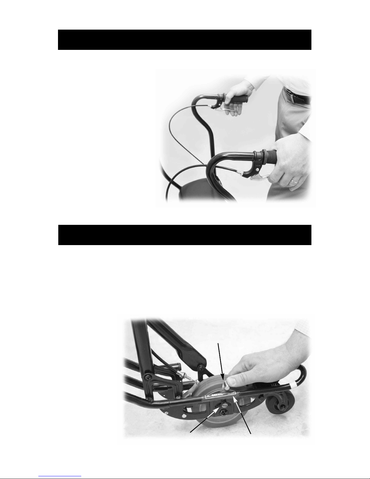
2) Locate the
tension locking bolt and
loosen it with
a screw driver.
To increase
rolling resistance, move
the tension
lever toward
— 7 —
B. Braking
C. Tension Control Adjustment (Optional)
Tension locking bolt
Tension lever
Tension indicator (sticker)

the front of the walker. On the frame just below the tension
lever is an indicator for adjusting the tension lever. “H” stands
for Higher tension and “L” stands for Lower tension.
3) Re-tighten the
tension locking bolt
to hold the position
of the tension lever.
4) Remember to
squeeze one of the
hand brakes while
testing the walker.
Test the rolling
speed of the walker,
if you need more or
less resistance adjust
accordingly.
To sit down, you can either turn
around while holding the handlebar, or pivot the U-Step II
around so that it is positioned
behind you and then sit down
on the seat.
When you are sitting on the
U-Step II you are facing backwards relative to the moving
direction of the U-Step II.
— 8 —
j
WARNING:
While sitting, DO NOT push
off with your feet to move
the U-Step II. This is unsafe.
D. Sitting Down

The U-Step II has a patented
spring-loaded front caster
that enables it to roll over
obstacles, such as door molding strips and cracks in the
sidewalk. It will help you ride
over obstacles as high as one
half-inch.
By removing the safety pins
that stop the rear wheels from
springing up, you can navigate
up larger obstacles such as
curbs without lifting the walker.
You can go up a curb or small
step by either stepping down
on the back of the base or just
by pulling back on the handlebars, you can raise the front of
the walker to go up a curb or
small step.
After raising the front
end, release the
brake and roll up the
obstacle. This feature
requires reasonable
balance and is not
appropriate for everyone. If you feel
unsafe using this feature, keep the locking
pins in place.
— 9 —
E. Walking Over Obstacles
Locking pins

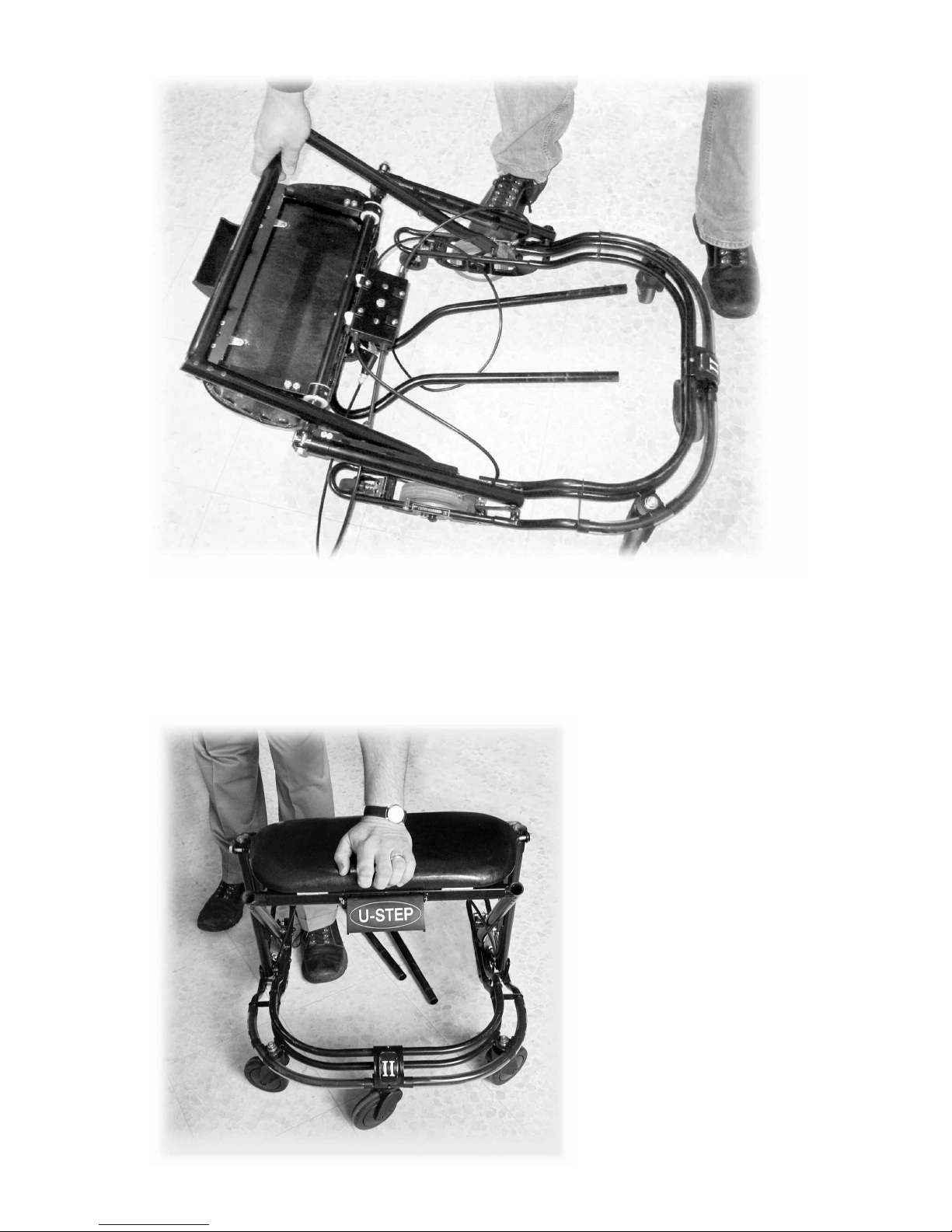
1) With the U-Step II
in front of you, raise
the release lever in
front of the seat and
tilt the seat upward.
2) Reach down and
pull up on the horizontal bar that has a
sticker on it reading
“
Lift Here to Fold”
until the U-Step II
folds up.
— 10 —
F. Transporting Your U-Step II
Release Lever
— 11 —
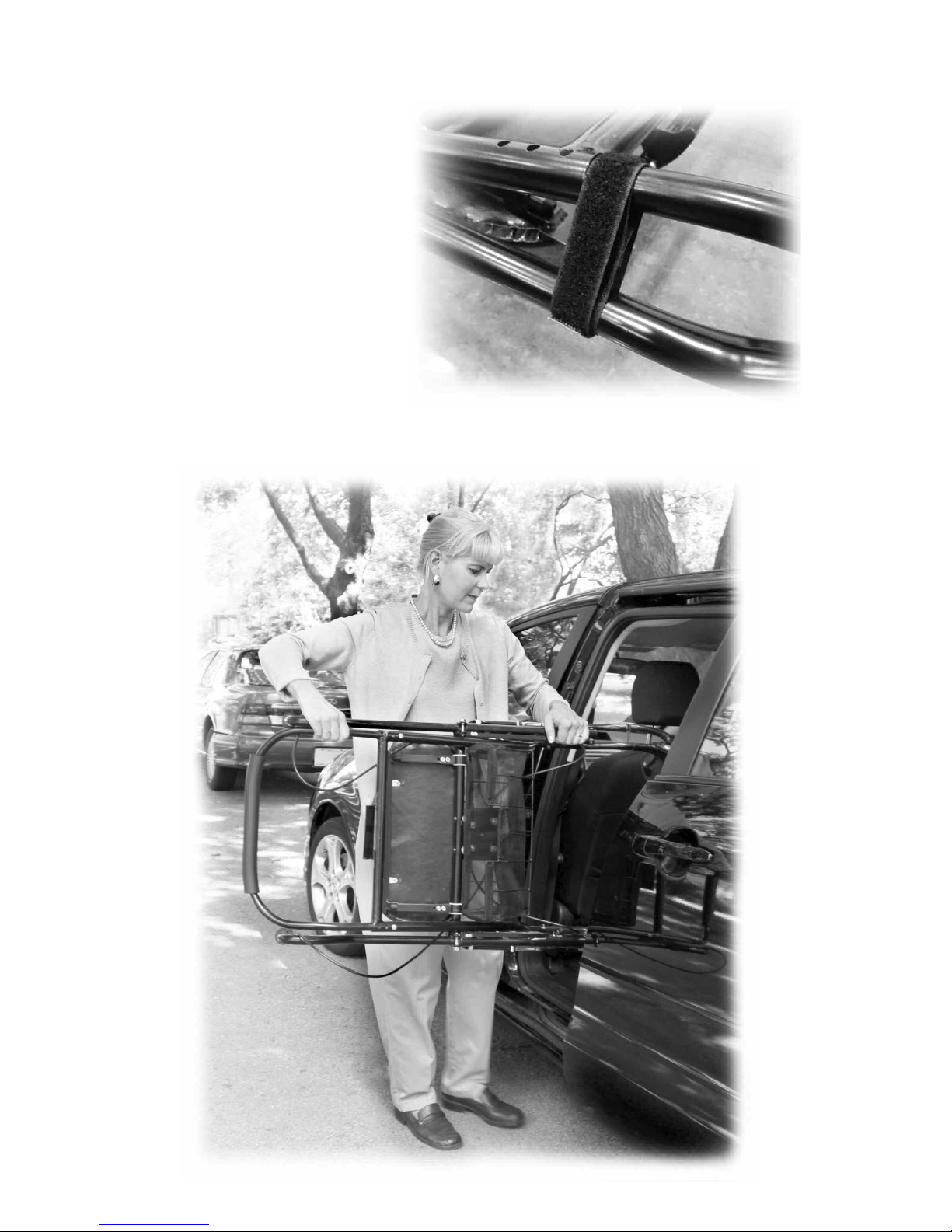
3) Secure the Velcro
strap to stop the walker
from folding. The
orange tab on the end
of the Velcro is to help
you see the side of the
Velcro with hooks for
securing the strap.
4) Hold the U-Step II by the side to place it into your vehicle.

1) Release the Velcro strap
holding the U-Step II in the
folded position.
2) Allow the U-Step II to open
– with the base on the ground.
3) Press the seat down in the
middle until the Release Lever
snaps into place.
4) You can put the Velcro strap inside the basket so that it is
not hanging down.
1) Alternative Brake Accessory –
Included with your U-Step II is the alternative brake accessory.
This allows a person to operate the brakes from a Horizontal bar
that attaches at the handles.
Installation instructions below:
a. Loosen height adjustment bolts on the left and right side
with the 13-millimeter wrench supplied.
b. Carefully insert the ends of the brake accessory into the
rear of each handlebar until the push pin engages in the holes
on the walker.
— 12 —
H. Accessories
G. Setup After Transporting
j
SAFETY NOTE:
It is very important to press the
seat down until the Release Lever fully snaps into place.

c. Adjust the height of the
handlebars so that the horizontal bar is at a comfortable
height for you.
d. Re-tighten the height
adjustment bolts.
e. The pull-up rod below should be positioned below the
hand brakes so that when the rod is pulled up the hand brakes
are squeezed.
f. If you use this Alternative Brake setup, you may want to
remove the backrest in front so that you can sit down on your
U-Step II from the front.
2) Laser and Sound Cueing Module —
Primarily used by those with Parkinson’s freezing but can be
used by anyone with an irregular gait pattern. The Laser and
Sound Cueing Module can help you get started, normalize your
walking, and increase your stride. First press the red button on
the module – that is located below the seat. This will activate
the Laser cueing function. A bright red laser line will be projected on the floor to guide your steps.
To activate the Sound Cueing, press and hold the top black button in for a few seconds. You will then hear the beeping. To set
the beep pattern to be
faster, press the top black
button. To slow down the
beep pattern, press the bottom black button.
The sound cueing will only
work when the laser cueing
is on. To turn it off, you
— 13 —

need to press the red button and turn off the whole unit. If you
leave the laser on for about ten minutes without using it, the
laser will turn off automatically to conserve your battery.
3) Replacing the Batteries of the
Laser and Sound Cueing Module —
Remove the screws
holding the plastic
cover to the metal
junction. Carefully
remove the battery
from the unit. It might
be held in with a strap
that needs to be
removed.
The battery is a #123 three-volt battery. You can purchase it in
most drug stores and electronic stores. You can also ordered it
directly from In-Step Mobility. Re-install the plastic cover using
the screws supplied.
4) Optional Weights —
Although the U-Step II is very stable, we do offer weights as
an accessory to increase the stability of the walker.
These
weights easily secure to
the base of
the U-Step II
using Velcro
straps
.
— 14 —

I. Maintenance
J. Warranty
j
NOTE: DO NOT pull on the cabling. Pulling on a
cable can cause it to become kinked or stretched out
of shape, which could prevent the braking system
from functioning properly. A damaged cable should
be replaced. Please have your U-Step II serviced if
the cabling becomes damaged.
Your U-Step II Walking Stabilizer is warranted for a full year from
purchase, to work properly and be free from any defects in
materials and workmanship. Additionally, the frame is warranted for three years from the date of purchase.
In the event of a defect covered by this warranty, we will, at our
option, repair or replace the device. In the event of a problem,
you will need to return the walker for repair at your cost. We will
fix the product or replace it and send it back to you at our cost.
This warranty does not cover device failure due to owner's misuse or negligence.
In the event of a minor problem, In-Step Mobility Products will
attempt to resolve the issue by sending replacement parts.
If you have a question about your U-Step II or this warranty,
please contact In-Step Mobility Products at
1-800-558-7837.
— 15 —
Clean your U-Step II with a clean, damp cloth when necessary.
Periodically check some of the moving components for wear.
On a daily basis, check over the U-Step II by trying the brakes.
Please call your U-Step II representative or call
1-800-558-7837
if you experience any problems with the tension of the wheels
or with braking.

U-Step II Walking Stabilizer
Medicare
Reimbursable!
In-Step Mobility Products Corp.
8027 Monticello Ave., Skokie, IL 60076
walkers@ustep.com www.ustep.com
1.800.558.7837
— 16 —
Passive Control Specifications
(Model US-PC2)
Model number ....................................US-PC2
Medicare code (HCPC) ........................#E0147
Weight capacity ..................................375 lbs
Height adjustment range..................................
..................accommodates users 4’10” to 6’2”
Height customization ..........................available
Size of Padded Seat............................19” x 8”
Height from floor to seat ............................22”
Overall width ............................................23”
Length ......................................................25”
Folded dimensions...... approx. 42” x 23” x 10”
Turning circle ............................................29”
Weight ..................................................20 lbs
Material of frame ............................................
............................
Tubular Steel and Aluminum
— Patent Pending —
 Loading...