

INSTEON wall switch Owner's Manual

Insteon Wall Switch
Owner’s Manual

Contents
Getting Started
Insteon Wall Switch 4
Dimmer Switch & On/O Switch
High-Wattage Dimmer Switch
Tools Needed for Installation
Disconnect Power
Installation
Installation Diagrams
Standard Switch 10
Three-Way Switch 11
Four-Way Switch 12
Insteon Links
Understanding Linking 14
Linking to the Insteon Hub 16
Linking with a Single-Button Controller 17
Linking with a Multi-Button Controller 18
Multi-Linking or Making a Scene 19
Unlinking from a Single-Button Controller 20
Unlinking from a Multi-Button Controller 21
Multi-Unlinking or Removing a Scene 22
Local Programming
Factory Reset
Software-Only Features
Beep on Button Press 29
Blink on Trac
Disable Local Programming
Error Blink
LED Brightness 30
Appendix
Specications 33
Troubleshooting 36
Certications and Warnings 38
Product Warranty 39

Getting Started
Everything you need to quickly get up and running.
3
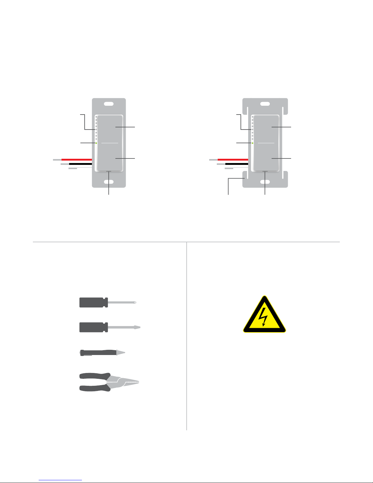
Insteon Wall Switch
Dimmer Switch & On/O Switch High-Wattage Dimmer Switch
Brightness
LEDs
On
Hold to
Status LED Status LED
Set Button Set ButtonHeat Sink Tab
Brighten
O
Hold to Dim
Brightness
LEDs
(1000W Only)
Tools Needed for Installation Disconnect Power
On
Hold to
Brighten
O
Hold to Dim
Phillips Screwdriver
Flathead Screwdriver
Voltage Detector
Wire Cutter / Stripper
Always disconnect power before
installation. Contact Insteon
Support when uncertain about
installation.
1-866-243-8022
4
SMOKE AND CARBON
MONOXIDE ALARM
a
1:30
iOS
BUSINESS REPLY MAIL
ATTN: INSTEON
16542 MILLIKAN AVE
IRVINE CA 92606
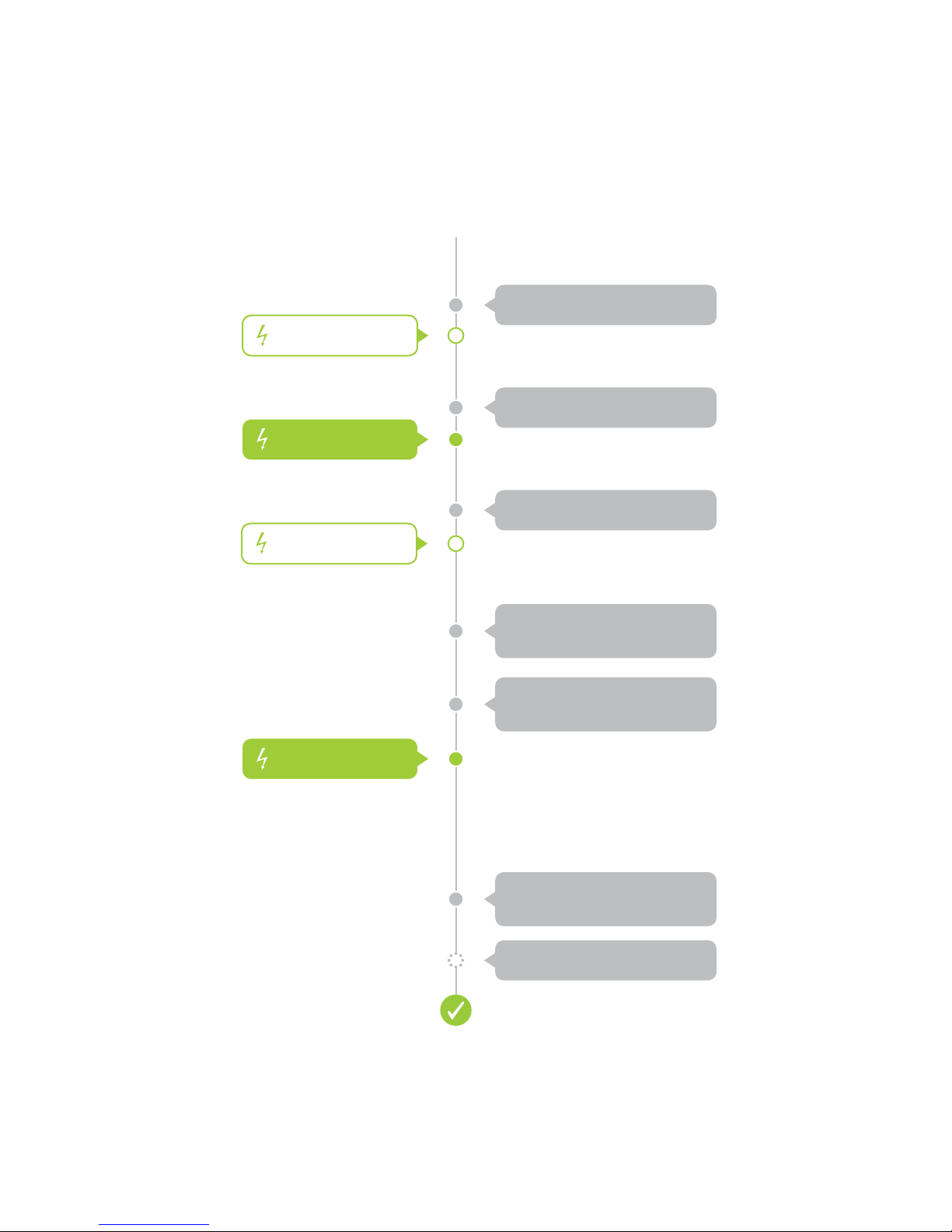
Disconnect Power
Installation
Unbox and read instructions
Reconnect Power
Disconnect Power
Reconnect Power
Remove the old switch
Identify Line and Load wires
Connect the switch wires to
the junction box wires
Carefully install the switch
into the junction box
Test the switch by tapping
the paddle to turn on and o
Install wall plate
5
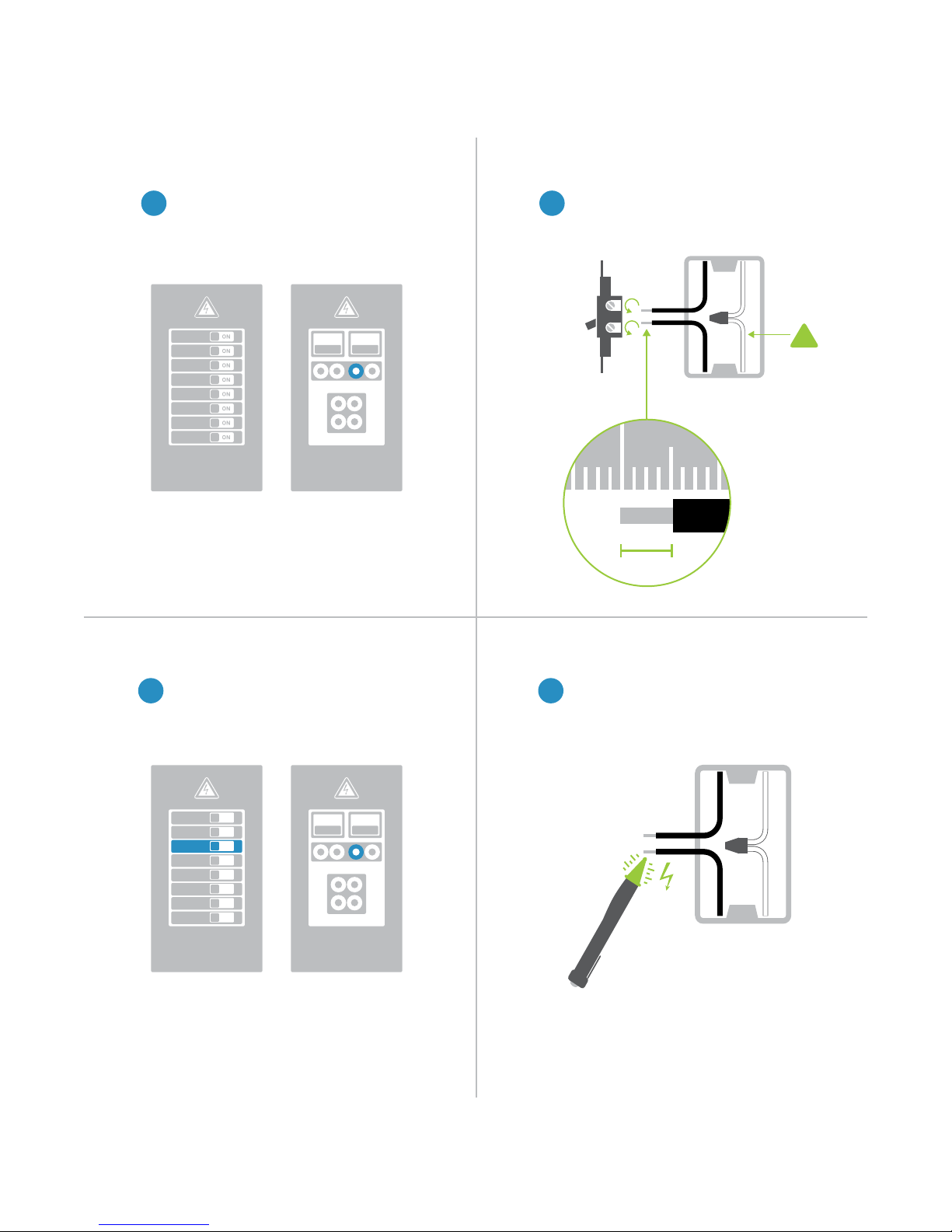
Installation
1 2
Disconnect Power Remove the Old Switch
Turn o power to your switch at the
1 2
electrical service panel.
Remove the old switch and disconnect
the wires. If your box lacks neutral
wires, stop and contact support.
ON ON
or
Circuit Breakers
Fuse Panel
Turn on power at the circuit breaker.
½”
12mm
Identify Line and LoadReconnect Power
Use a voltage detector or multi-meter
43
to identify line and load. Line will be
energized.
!
Neutral
Wire
ON
ON
ON
ON
ON
ON
ON
ON
Circuit Breakers
or
Fuse Panel
ON ON
6
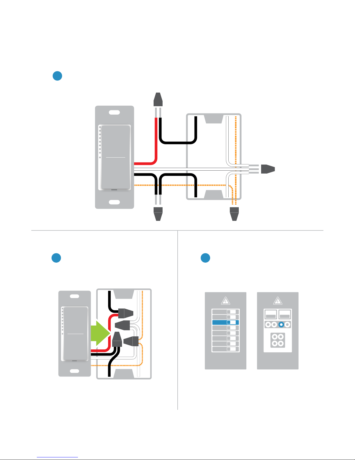
Installation
Wire-In The Switch
Turn o power at the circuit breaker. Connect the Wall Switch wires to the identied wires in the junction
5
box. Verify that the wire nuts are secure and that no exposed copper wire is visible except for the bare
ground wire. Additional wiring diagrams can be found in the Installation Diagrams section.
Load
Neutral
Mount the Wall Switch into the junction
box with the LED bar on the left.
Line
Ground
Reconnect PowerInstall the Switch
Turn power on to the switch at the circuit
76
breaker panel.
ON
ON
ON
ON
ON
ON
ON
ON
or
Circuit Breakers Fuse Panel
ON ON
7
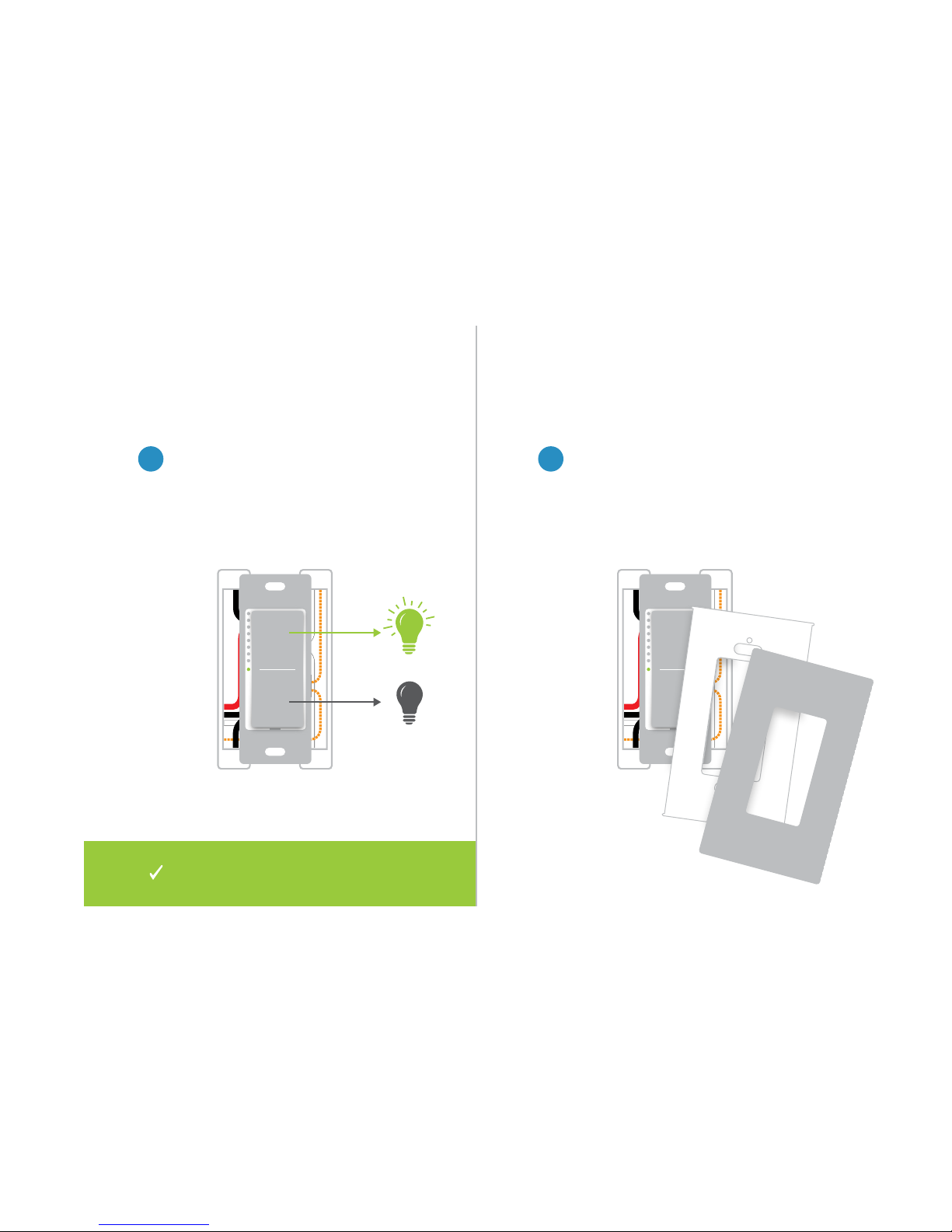
Test your Wall Switch by tapping the
paddle to turn On and O. Press and
hold to dim or brighten.
Installation
Install Wall PlateTest the Switch
Complete installation by reattaching
98
your wall plate. For the best look, us an
Insteon Screwless Wall Plate.
Installation of your Wall Switch is
now complete.
8

Installation Diagrams
Use the installation diagrams in this section to help you wire your Wall
Switch, everything from straight forward, single-switch to multi-way and
beyond.
9
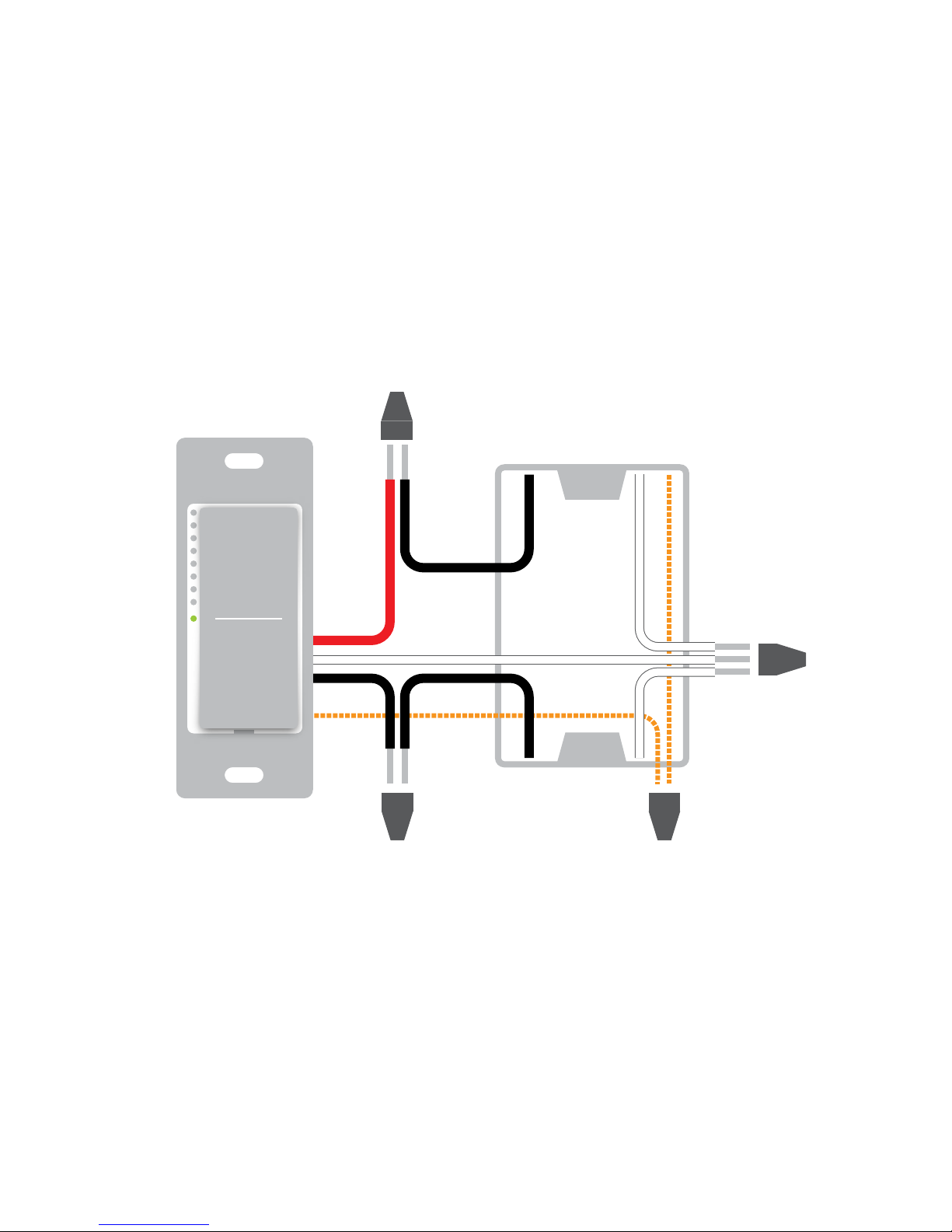
Standard Switch
Load
Line Ground
Neutral
10
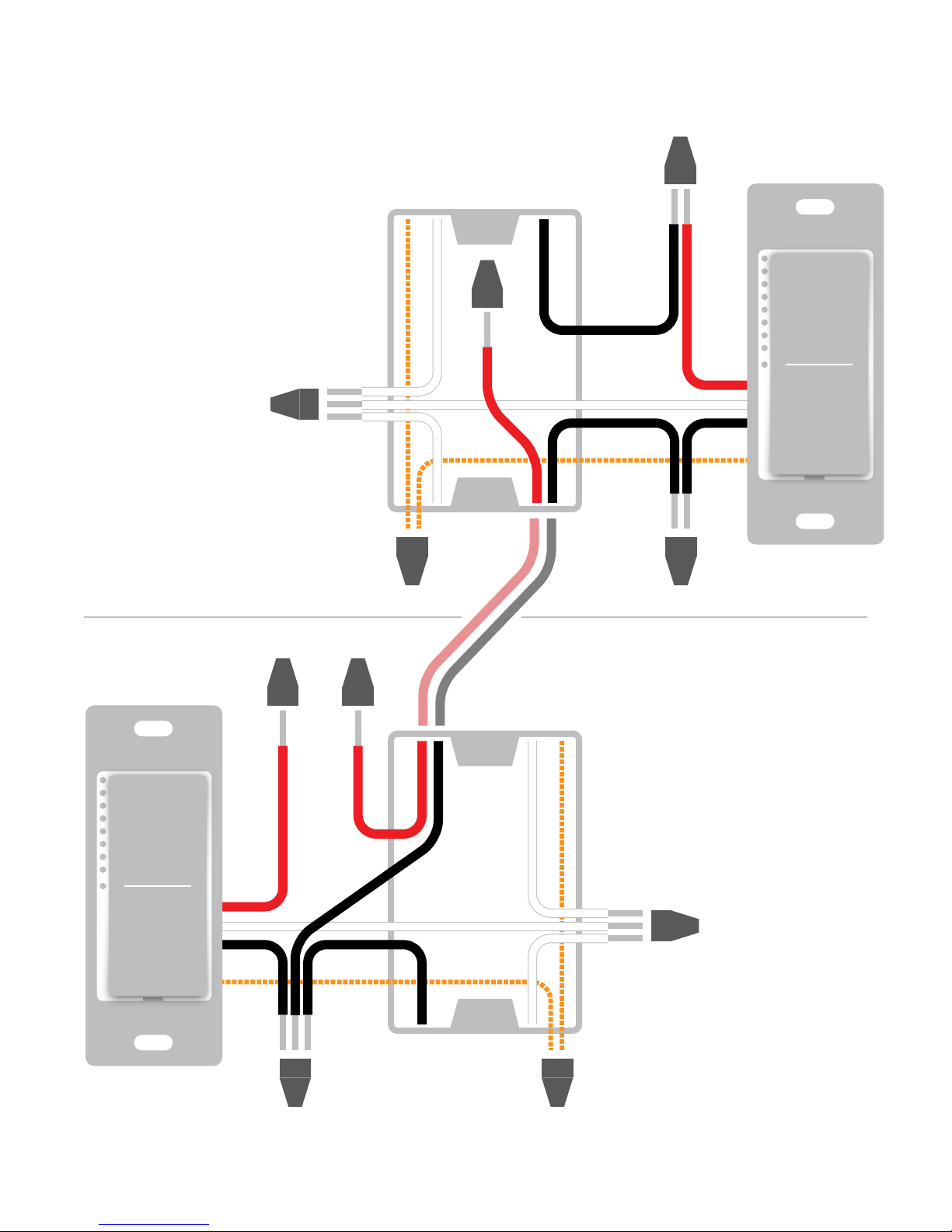
Neutral
Three-Way Switch
Load
Traveler
Not Used
Load
Not Used
LineGround
Neutral
Line Ground
11
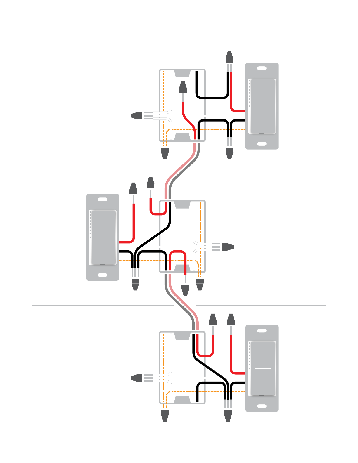
Traveler 2
Not Used
Neutral
Four-Way Switch
Load
Load
Not Used
Ground
Line
Netural
GroundLine
Traveler 1
Not Used
Load
Not Used
Neutral
Ground
Line
12
 Loading...