

Page 1
Quick-Start Guide
INSTEON™ Thermostat Adapter, Totaline™ / Venstar™
Model: #2441V
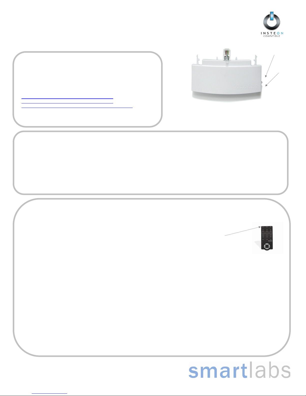
Introduction
LED
The INSTEON Thermostat Adapter adds remote control and monitoring to 3
compatible models of Totaline
plugs into the bottom of compatible thermostats and communicates via
INSTEON RF giving you wireless remote control and monitoring from
anywhere in your home, or the world.
The 3 compatible models are:
1-Day Programmable Venstar Thermostat (30410A)
7-Day Programmable Venstar Thermostat (30411A)
7-Day Programmable, Dual-Fuel Venstar Thermostat (30412A)
Note: To use the above mentioned thermostats, make sure your install
location’s wiring has 5 wires or check with a local installer.
TM
/ VenstarTM brand thermostats. It simply
INSTEON Thermostat Adapter
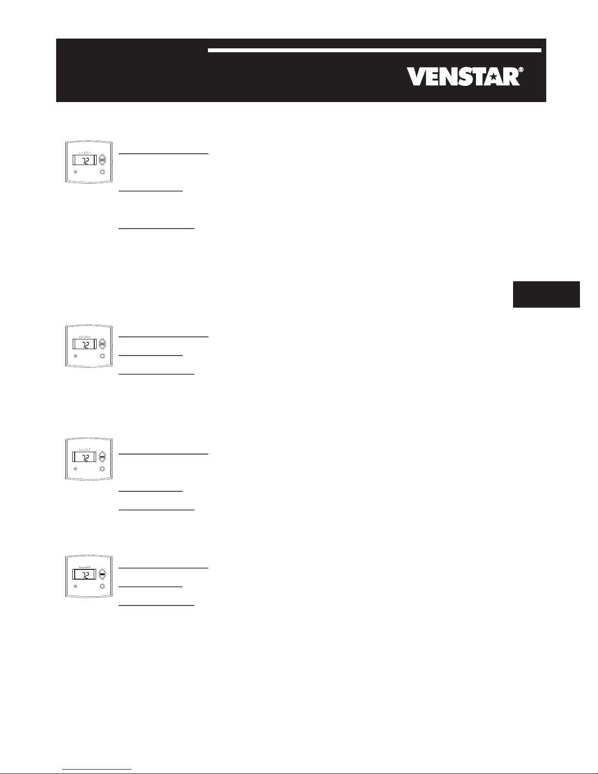
Installation
1) Simply plug the INSTEON Thermostat Adapter into the jack on the bottom of your thermostat
Green LED will turn on
Un-Install
1) Open the front cover of the thermostat by gently pulling the right edge of the cover towards you
2) While pressing firmly on the small round button (center, bottom of thermostat) pull down gently on the INSTEON Thermostat Adapter
INSTEON Thermostat Adapter will disconnect from the thermostat
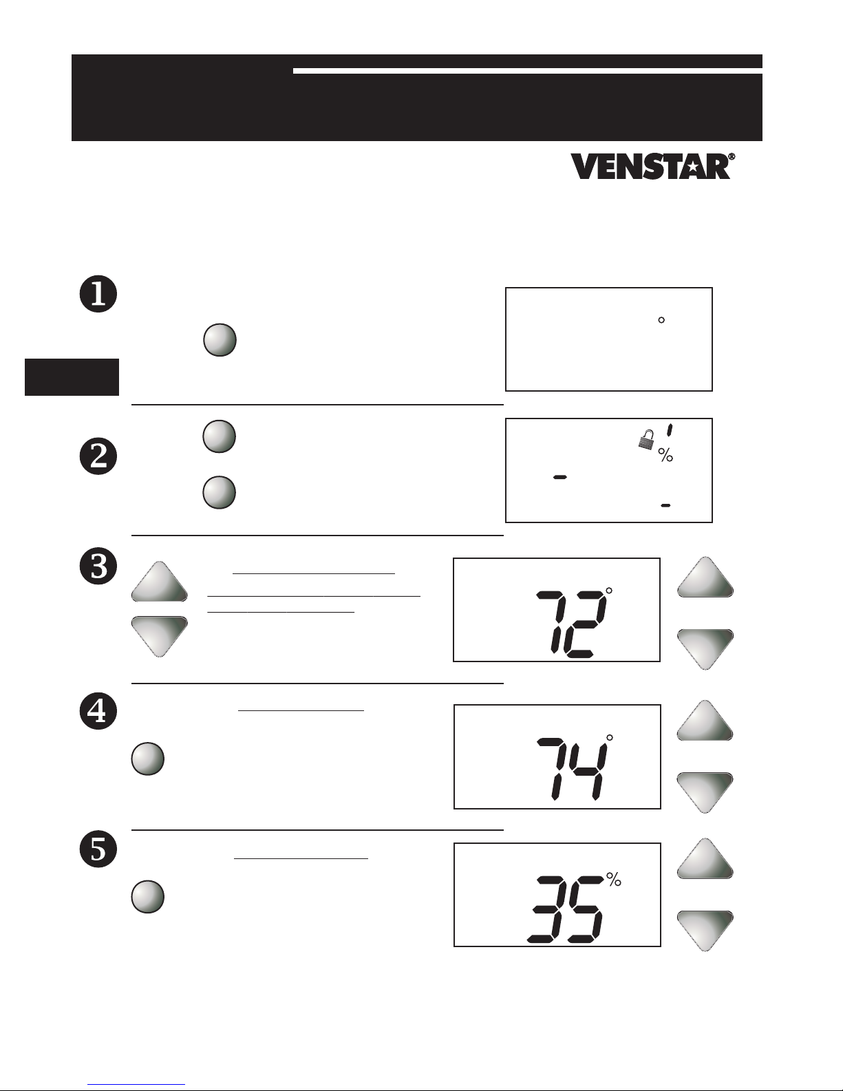
Adding your Thermostat Adapter to a Scene on an INSTEON Compatible Controller
Button
For example, let’s say you would like to remotely control your thermostat to 73 degrees, heat mode from the comfort and convenience of your couch,
using the Scene A button on your RemoteLinc (If you want to use another INSTEON Compatible Controller, see its user manual)
Note: Linking your Adapter to a scene allows your thermostat to go to a chosen setting.
Here, you will link your Scene A button to “recall” both the setpoints and mode of the thermostat.
1) Tap the mode button on your thermostat until the mode indicated is heat
2) Tap the up and/or down arrows on your thermostat until the temperature set point is 73 degrees
3) Press & hold the top of the Scene A button on your RemoteLinc (for about 10 seconds) until it beeps
LED will start blinking (Press & hold for 10 seconds works for just about every INSTEON-compatible Controller;
please check the controller’s owner’s manual if you need help)
4) Press & hold the button on the INSTEON Thermostat Adapter (for about 5 seconds)
LCD display on your thermostat will briefly display all its characters, then return to normal
INSTEON Adapter’s LED will blink off faintly, then return to steady on
RemoteLinc will beep and its LED will stop blinking
5) Tap the mode button on your thermostat (this will temporarily change the operating mode to allow you to test your remote control)
Your thermostat’s mode will change to cool
6) Now to test your new link, tap the Scene A (up arrow) on your RemoteLinc
Your thermostat should return to heat mode with a 73-degree set point
7) Repeat steps 1 through 6 for as many scenes and setpoints on your INSTEON-Compatible Controller as you wish.
Note: Sending an Off command will not change the mode or setpoints of the thermostat. These commands are ignored to minimize unintended results.
Note: Different set points can be linked to different buttons should you need more flexibility.
Page 1 of 2
Rev. 20080213
Page 2
Quick-Start Guide INSTEON Thermostat Adapter
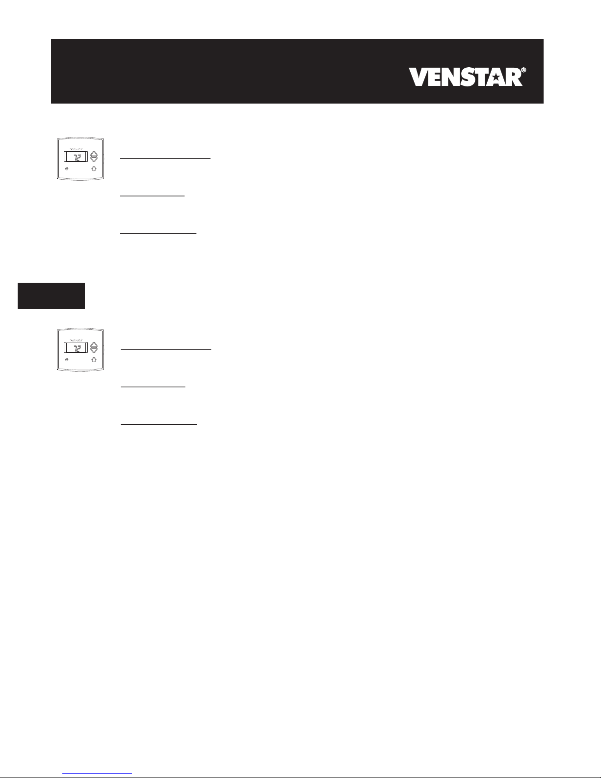
Removing from a Scene
1) Put your Controller into “Delete from Scene” mode (usually “Unlinking” mode (two 10-second press & holds) – please check its Owner’s Manual if
you need help)
2) Press & hold the INSTEON Thermostat Adapter’s button for about 5 seconds
The LCD display on your thermostat will briefly display all its characters, then return to normal
The INSTEON Adapter’s LED will blink off faintly, then return to steady on
Factory Reset
1) Unplug the INSTEON Thermostat Adapter from your thermostat (see Un-Install section on page 1 for details)
2) Press & hold the button on the INSTEON Thermostat Adapter
3) While continuing to hold the button, plug the INSTEON Thermostat Adapter back into your thermostat
4) Continue to hold the button for approximately 5 seconds
All user settings will be erased and the unit restored to its factory settings
Advanced Operations
Using software, you will be able to integrate the automation of your thermostat with the wide array of INSTEON compatible products saving you
time and energy. For example, applications can include having an email sent to you if the temperature goes above or below any chosen set points,
have a “goodbye” scene automatically set back your thermostat, etc. – the applications are almost endless. Check with your favorite INSTEON
Compatible Software for their latest support for this product.
Specifications FCC Compliance Statement
INSTEON communications RF
INSTEON Controller functionality Not supported
INSTEON Responder functionality Supported
INSTEON message repeating Supported, always on
Mode control Heat, Cool, Auto, OFF
Fan control On, Auto
Degree format Fahrenheit (Celsius is not available)
Maximum number of INSTEON
scenes / links
All Linking Supported (10 sec set button push n hold)
Unlink Supported (10 seconds press n hold, twice)
Heat set point Supports all set points of Thermostat
Cool set point Supports all set points of Thermostat
Temperature status request Supported
Humidity status request Supported
Mode status request Supported
Fan status request Supported
X10 Not supported
Dimensions 2.89” W x 1.75” H x 0.58” D
LED Green
Interconnect type Male, RJ10 4 conductor (aka RJ22)
Input power 5VDC, 30 ma max (supplied by thermostat)
Installation Indoor use only
Approvals FCC, Industry Canada
Warranty 2 years
417
This device complies with FCC Rules Part 15.
Operation is subject to two conditions:
(1) This device may not cause harmful interference,
and
(2) this device must accept any interference that
may be received or that may cause undesired
operation. The digital circuitry of this device has
been tested and found to comply with the limits for a
Class B digital device, pursuant to Part 15 of the
FCC Rules. These limits are designed to provide
reasonable protection against harmful interference
in residential installations. This equipment
generates, uses and can radiate radio frequency
energy and, if not installed and used in accordance
with the instructions, may cause harmful
interference to radio and television reception.
However, there is no guarantee that interference will
not occur in a particular installation. If this device
does cause such interference, which can be verified
by turning the device off and on, the user is
encouraged to eliminate the interference by one or
more of the following measures:
x Re-orient or re-locate the receiving antenna of
the device experiencing the interference.
x Increase the distance between this device
and the receiver.
x Connect the device to an AC outlet on a
circuit different from the one that supplies
power to the receiver.
x Consult the dealer or an experienced radio/TV
technician.
WARNING! Changes or modifications to this unit
not expressly approved by the party responsible for
compliance could void the user's authority to
operate the equipment.
SmartLabs Limited Warranty – SmartLabs warrants to the original consumer of this product that, for a period of two years from the date of purchase, this product will be free from defects in material and
For HELP
workmanship and will perform in substantial conformity to the description of the product in the owner's manual and/or quick start guide. This warranty shall not apply to defects or errors caused by misuse
or neglect. © Copyright 2008 SmartLabs, 16542 Millikan Ave., Irvine, CA 92606-5027 – 866-243-8018 www.smartlabsinc.com
, call our friendly tech support @ 866-243-8018
Page 2 of 2
Rev. 20080213
Page 3
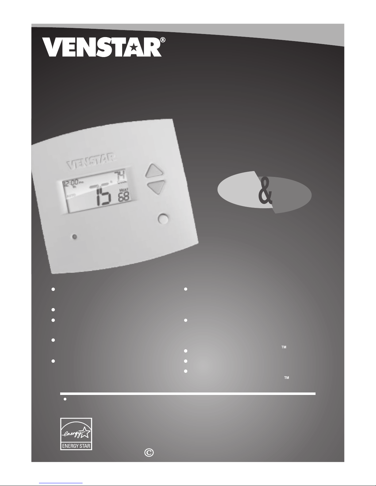
Digital
Digital
Thermostat
Thermostat
residential
THERMOSTAT
800
T1
7-DAY
7-DAY
PROGRAMMABLE
PROGRAMMABLE
Control up to 3 Heat &
2 Cool Stages
3 Configurable Outputs
Adjustable 2nd & 3rd Stage
Timers & Deadbands
Backlit Display & Button
Legends
Aux Heat Indicator
up to
up to
& 2-cool
& 2-cool
HEAT
COOL
Outdoor Sensor Ready
with High/Low Readouts
for the Day
Accepts Optional Humidity Module:
Controls Humidification and
Dehumidification
Accepts EZ Programmer
Accepts Optional IR Remote Control
Accepts Comfort Call
Phone Control Accessory
3-heat
3-heat
HEAT
PUMP
Use with most Air Conditioning & Heating Systems including: 1 or 2 Stage
Electric Cooling & 3 Stage Gas Heating, Heat Pump, Electric or Hydronic Heat.
INSTALLATION
INSTALLATION
INSTRUCTIONS
INSTRUCTIONS
Venstar Inc. 08/07
Page 4
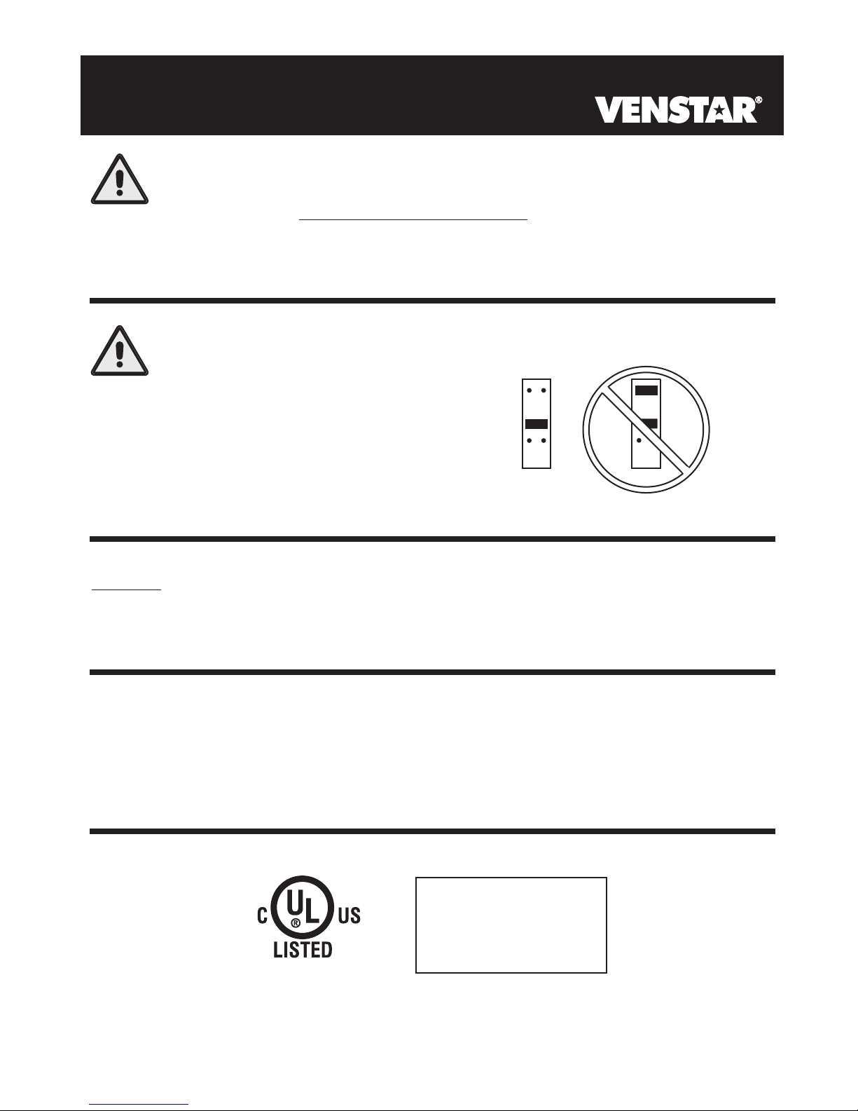
CAUTION
Follow the Installation Instructions before proceeding.
Set the thermostat mode to “OFF” prior to changing
settings in setup or restoring Factory Defaults.
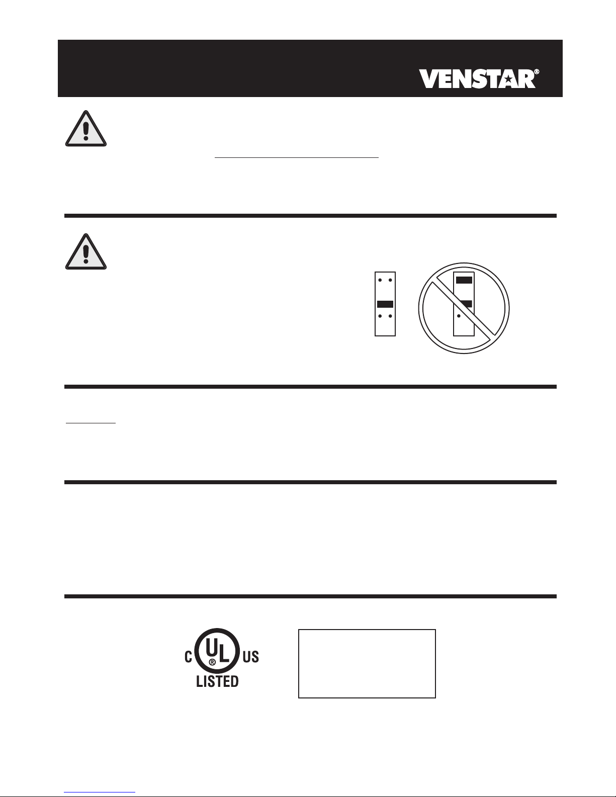
CAUTION
NEVER PUT MORE THAN ONE
JUMPER ON THE SAME MISC
JUMPER BLOCK!
THIS MAY DAMAGE YOUR
THERMOSTAT AND VOID
YOUR WARRANTY.
MISC3
OK
NOTE: Due to variations in environmental conditions, it is not
MISC3
always possible to achieve the desired humidification or
dehumidification setpoint.
This device complies with Part 15 of the FCC Rules. Operation is
subject to the following two conditions: (1) this device may not cause
harmful interference, and (2) this device must accept any interference
received, including interference that may cause undesired operation.
Thermostat T1800
Tested to Comply
c
with FCC Standards
C
F
4Z95
FOR HOME OR OFFICE USE
Page
i
Page 5

Table of Contents
Preparation
Remove & Replace the
Old Thermostat
Configuring the MISC
Outputs
Wire Connections
Wiring Diagrams
Test Operation
Calibrating the
Thermostat Sensors
TroubleShooting
1
2
3
4
5
6
7
8
Page iii
Page 6

SECTION 1
Preparation
1
Pm
I2:00
74
C
OOL
AUTO
H
EAT
72
accomplished by following these step by step
instructions. If you are unsure about any of these
steps, call a qualified technician for assistance.
Proper installation of the thermostat will be
Pm
I2:00
74
C
OOL
AUTO
H
EAT
72
Assemble tools
Flat Blade
Screwdriver
Wire cutter
& Stripper
Pm
I2:00
AUTO
Make sure your Heater/Air Conditioner is working
74
C
OOL
H
EAT
72
properly before beginning installation of the
thermostat.
Pm
I2:00
AUTO
Carefully unpack the thermostat. Save the screws,
74
C
OOL
H
EAT
72
bracket, and instructions.
Pm
I2:00
74
C
OOL
AUTO
Turn off the power to the Heating/Air Conditioning
H
EAT
72
system at the main fuse panel. Most residential
systems have a separate breaker for disconnecting
power to the furnace.
Page 1.1
Page 7

SECTION 2
Remove & Replace the Old Thermostat
2
Pm
I2:00
74
C
OOL
AUTO
H
EAT
72
Remove the cover of the old thermostat.
If it does not come off easily check for screws.
Pm
I2:00
74
C
OOL
AUTO
H
EAT
72
Loosen the screws holding the thermostat
base or subbase to the wall, and lift away.
Pm
I2:00
74
C
OOL
AUTO
H
EAT
72
Disconnect the wires from the old thermostat.
Tape the ends of the wires as you disconnect
them, and mark them with the letter of the
terminal for easy reconnection to the new
thermostat.
Pm
I2:00
74
C
OOL
AUTO
H
EAT
72
Keep the old thermostat for reference purposes,
until your new thermostat is functioning properly.
Page 2.1
Page 8

SECTION 3
Configuring the MISC Outputs
3
Section 3 Contents:
Configuring the Jumpers........3.2
Explanation of Jumper
Settings..................................3.3
Page 3.1
Page 9
C
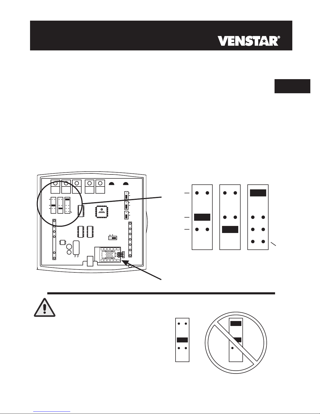
Configuring the Jumpers
For additional flexibility, your thermostat has three configurable
outputs. These outputs are designed to have different functions
depending on how the jumpers are set (below).
Each output, labeled MISC1, MISC2, and MISC3 may be set for one
of the five choices available.
In the diagram below, the MISC3 jumper has been set for HUM*
(humidification) operation, the MISC2 jumper has been set for
DEHUM* (dehumidification) operation, and the MISC1 jumper has
been set for W3 (3rd stage of heat) operation.
(FAN)
DEHUM
MISC2
W3
HUM
W1
Y1
MISC3 MISC2 MISC1
G
R
C
(MISC1
ONLY)
ELEC
GAS
HP
GAS
Y2
HUM
NO HUM
2
8
4
6
INSTALL HUMIDITY
MODULE WITH SENSING
ELEMENT OUTWARD
1
3
579
B
O
W2
MISC1
RS2
MISC3
RS+5
Z
X
1
Rs1
RSGND
Y
W3
HUM
DEHUM
MISC3 MISC2 MISC1
3
Y2
(MISC1
ONLY)
CAUTION
NEVER PUT MORE THAN
ONE JUMPER ON THE SAME
MISC JUMPER BLOCK!
DOING SO MAY DAMAGE
YOUR THERMOSTAT AND
VOID THE WARRANTY.
*The Humidity Module (sold separately) must
be installed to operate a humidification
and/or dehumidification system.
Page 3.2
MISC3
OK
MISC3
Page 10
Explanation of Jumper Settings
3
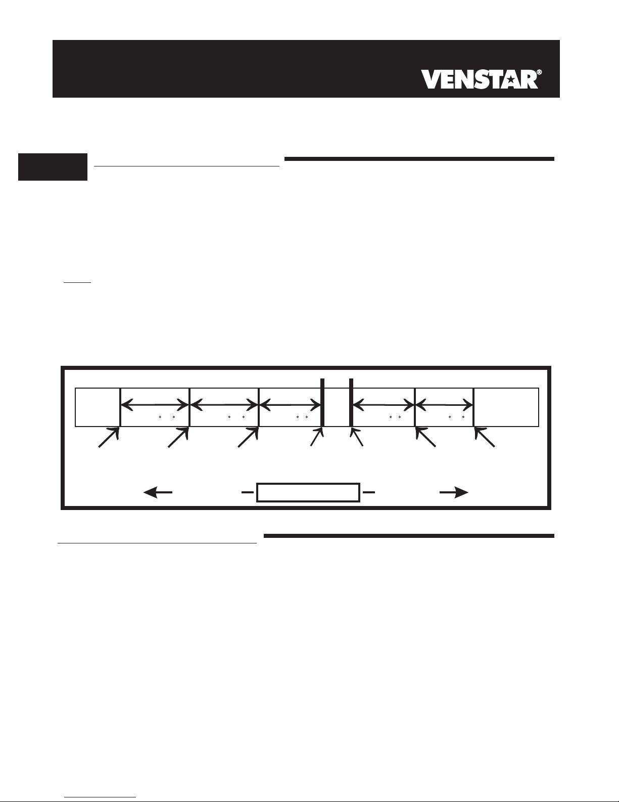
W3 MULTI-STAGE OPERATION EXPLAINED - SECTION 13 of the Owner’s
Manual
The 3rd Stage of Heat is turned on when:
(A) The 1st and 2nd stages have been on for the time required (steps #22
and #23, page 13.6). It is adjustable from 0-60 minutes and the default
And
is two minutes.
(B) The temperature from the setpoint is equal to or greater than: the set-
point plus the 1st stage deadband (step #19, 13.5), plus the 2nd stage
deadband (step #20, 13.5) plus the 3rd stage deadband (step #21,
13.5). This 3rd stage deadband is adjustable from 0-10 degrees and
the default is two degrees.
If the jumper for MISC1, MISC2, or MISC3 is set to W3, the corresponding MISC screw
terminal on the backplate will control a third stage of heat.
Cooling
1st Stage
turn on
3rd Stage
turn on
2nd Stage
turn on
Heating
Deadband Deadband DeadbandDeadbandDeadband
1st Stage
turn on
db 1 db 1db 2 db 2db 3
(adj. 1-6 )(adj. 0-10 )(adj. 0-10 ) (adj. 0-10 )(adj. 1-6 )
Heat
Setpoint
Cool
Setpoint
2nd Stage
turn on
W3 JUMPER SETTING
DECREASE INCREASE
TEMPERATURE
HUM JUMPER SETTING
If the jumper for MISC1, MISC2, or MISC3 is set to HUM,
terminal on the backplate will control a humidification system.
HUMIDIFICATION OPERATION - SECTION 9 of the Owner’s Manual
If your HVAC unit is equipped with a humidification system and the
Humidity Module (sold separately) has been installed, the thermostat will
provide power to the MISC1, MISC2, or MISC3 terminal of the thermostat
when the humidity in the home falls below the humidity setpoint you have
chosen. The value for this setpoint ranges from 0% to 60%. If no
humidity is desired or if a humidification system has not been installed, set
the value to OFF.
Page 3.3
the corresponding MISC screw
Page 11

Explanation of Jumper Settings (continued)
DEHUM JUMPER SETTING
If the jumper for MISC1, MISC2, or MISC3 is set to DEHUM,
terminal on the backplate will be connected to the dehumidification terminal of a furnace board.
NOTE: Not all furnaces have a dehumidification terminal.
DEHUMIDIFICATION OPERATION - SECTION 10 of the Owner’s Manual
If your HVAC unit is equipped with a dehumidification system the thermostat will
operate in one of two ways.
1) Normally Closed (NC): The thermostat will de-energize the MISC1, MISC2,
or MISC3 terminal of the thermostat (this MISC terminal is connected to the
DEHUM terminal on your furnace) to allow the fan to run in low speed when
the humidity in the home is above the dehumidify setpoint you have chosen
and there is a call for 1st stage cooling.
2) Normally Open (NO): The thermostat will energize the MISC1, MISC2, or
MISC3 terminal of the thermostat (this MISC terminal is connected to the
DEHUM terminal on your furnace) to allow the fan to run in low speed when
the humidity in the home is above the dehumidify setpoint you have chosen
and there is a call for 1st stage cooling.
the corresponding MISC screw
3
Page 3.4
Page 12
Explanation of Jumper Settings (continued)
3
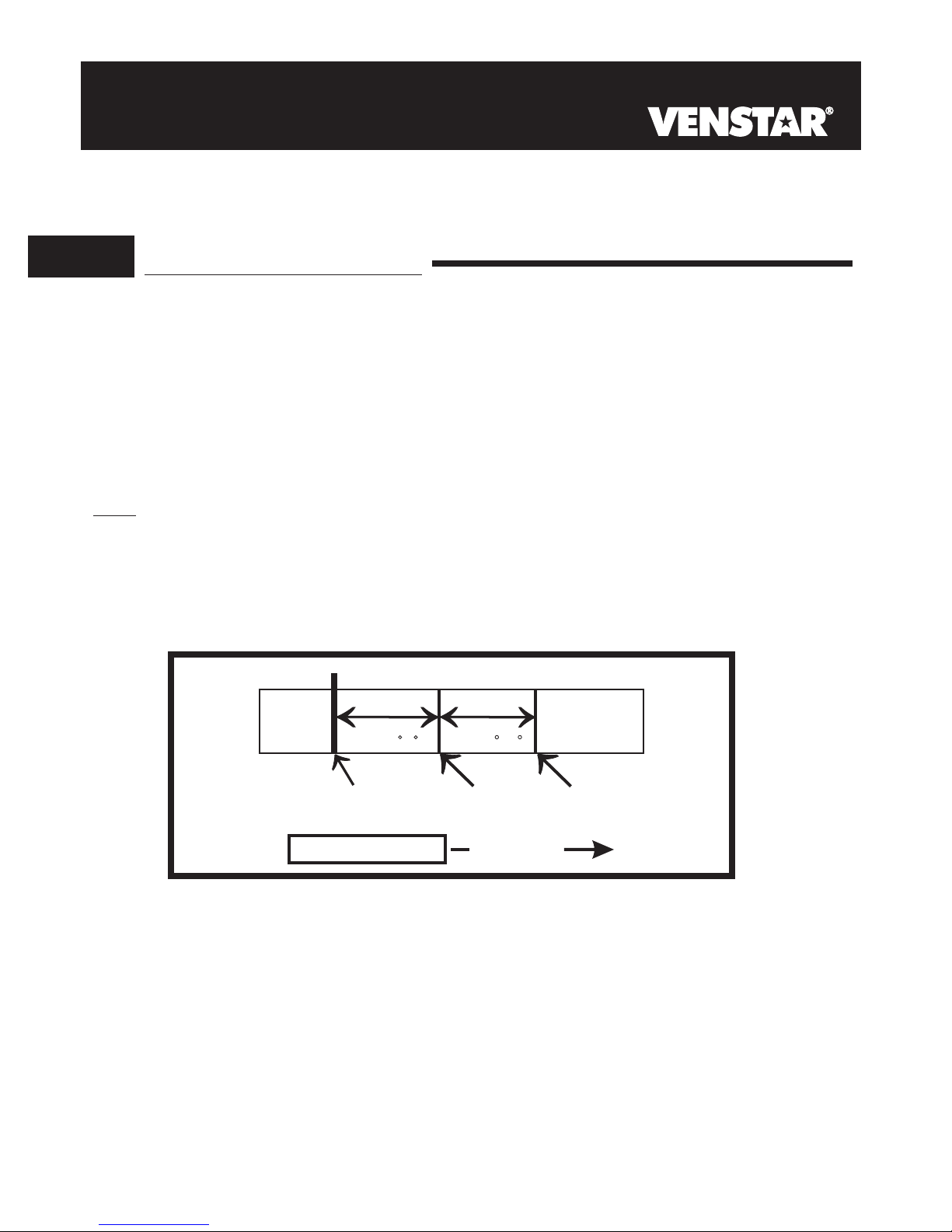
Y2 JUMPER SETTING
If the jumper for MISC1 is set to Y2 the
second stage of cooling.
MISC1 screw terminal on the backplate will control a
Y2 OPERATION - SECTION 13 of the Owner’s Manual
Control up to two Cool stages.
The 2nd Stage of heat or cool is turned on when:
(A) The 1st Stage has been on for the time required (step #22,
page 13.6). It is adjustable from 0-60 minutes and the default
is two minutes.
And
(B) The temperature spread from the setpoint is equal to or greater
than: the setpoint plus the deadband (step #20, page 13.5), plus
the 2nd deadband (step #20, page 13.5). This 2nd deadband is
adjustable from 0-10 degrees and the default is two degrees.
db 1 db 2
Cooling
DeadbandDeadband
(adj. 0-10 )(adj. 1-6 )
TEMPERATURE
Cool
Setpoint
1st Stage
turn on
INCREASE
Page 3.5
2nd Stage
turn on
Page 13

SECTION 4
Wire Connections
Pm
I2:00
74
C
OOL
AUTO
H
EAT
72
If the terminal designations on your old thermostat
do not match those on the new thermostat, refer
to the chart below, or the wiring diagrams
that follow.
Wire from the
old thermostat
terminal marked
G or F Fan G
Y1, Y or C
W1, W or H
C
O/B
W2
MISC1
Function
Cooling Y1
Heating
PowerRh, R, M, Vr, A R
Common
Rev. Valve
2nd Stage Heat
Configurable Output #1
4
Install on the
new thermostat
connector marked
W1/O/B
C
W1/O/B*
W2
MISC1
MISC2
MISC3
RS+5
RS1
RSGND
RS2
* O/B is used if your system is a Heat Pump.
** For instructions on connecting these terminals see page 14.2
of the Owner’s Manual.
Configurable Output #2
Configurable Output #3
Remote Sensor +5vdc
Remote Sensor Signal
Remote Sensor Ground
Remote Sensor Signal #2
Page 4.1
MISC2
MISC3
RS+5**
RS1**
RSGND**
RS2**
Page 14

SECTION 5
Sample Wiring Diagrams
Section 5 Contents:
5
HVAC Equipment Wiring............5.2
MISC1, MISC2, and MISC3
Wiring........................................5.6
Page 5.1
Page 15
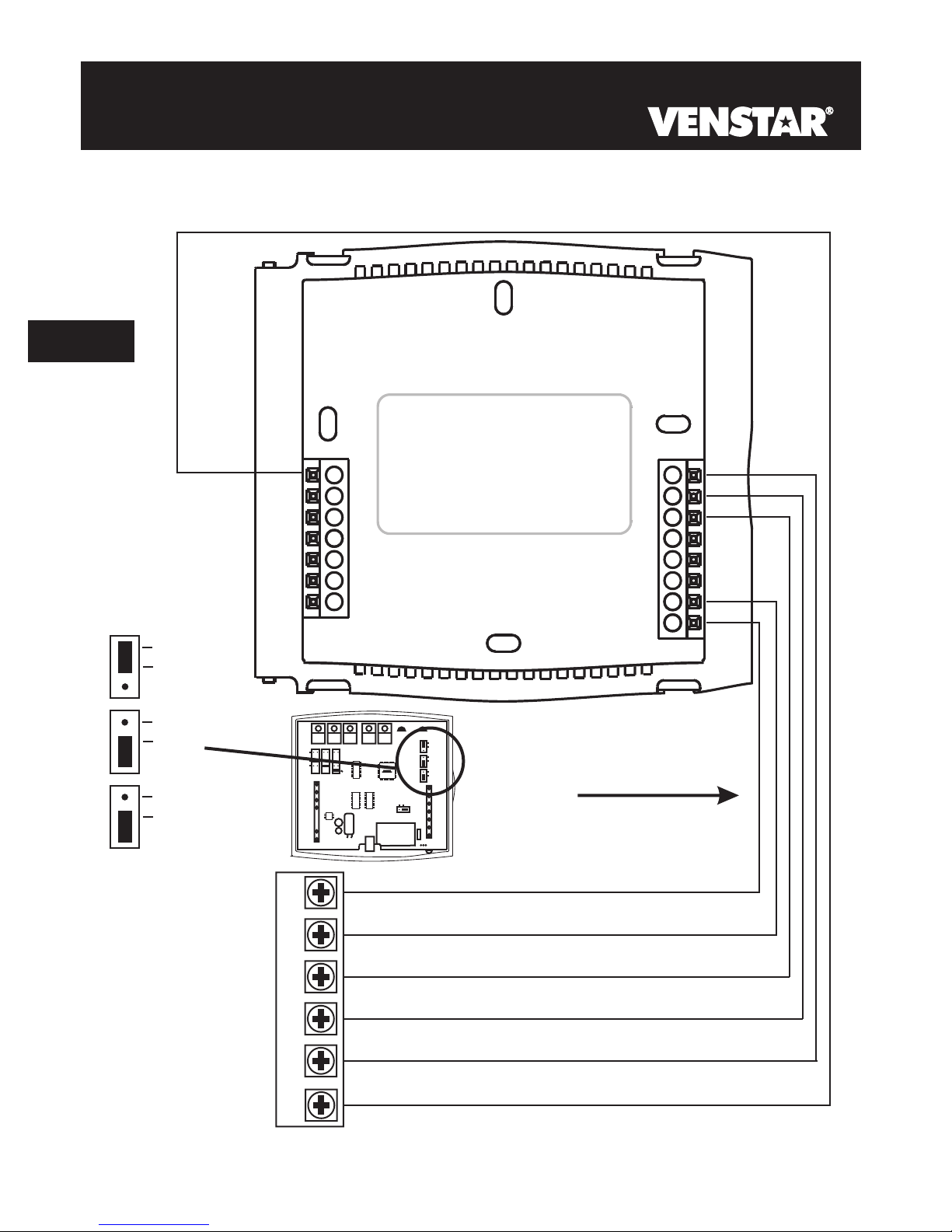
6 Wire, 1 Stage Cooling, 1 Stage Heat
Residential & Commercial 1 Stage Cooling,
with 1st stage Gas Heat
OR
Commercial Heat Pump 1 Stage Cooling
with 2 Stage Heat
5
(FAN)
ELEC
GAS
HP
GAS
B
O
24 vac common
HUM
DEHUM
MISC2
W3
MISC3 MISC2 MISC1
W1
Y1
G
R
C
W2
MISC1
RS2
MISC3
RS+5
RS1
RSGND
Y2
(MISC1
ONLY)
HUM
INSTALL HUMIDITY
MODULE WITH SENSING
ELEMENT OUTWARD
C
W1/O/B
Y1
G
MISC2
R
C
(FAN)
ELEC
GAS
HP
GAS
B
O
W2
MISC1
NO HUM
RS2
MISC3
RS+5
RS1
RSGND
6 Conductor 18 gauge
unshielded cable from the
thermostat to the equipment.
24 vac return
fan relay
compressor relay
1st stage heat circuit
2nd stage heat circuit
R
G
Y1
W1
W2
Page 5.2
Page 16
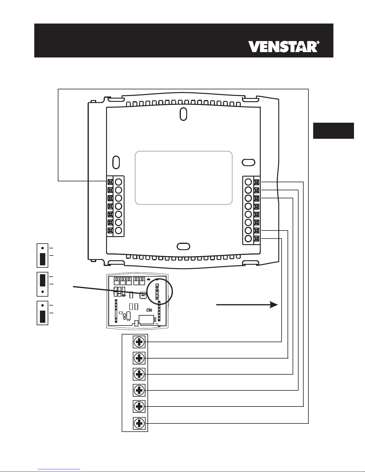
6 Wire, 1 Stage Cooling, 1 Stage Heat
Residential & Commercial 1 Stage Cooling,
with 1st stage Electric Heat
5
(FAN)
ELEC
GAS
HP
GAS
B
O
24 vac common
DEHUM
MISC2
W3
HUM
W1
Y1
G
C
MISC3 MISC2 MISC1
R
W2
MISC1
RS2
MISC3
RS+5
RS1
RSGND
Y2
(MISC1
ONLY)
INSTALL HUMIDITY
MODULE WITH SENSING
ELEMENT OUTWARD
W1/O/B
Y1
G
MISC2
R
C
(FAN)
ELEC
GAS
HP
GAS
B
O
W2
MISC1
HUM
NO HUM
RS2
MISC3
RS+5
RS1
RSGND
6 Conductor 18 gauge
unshielded cable from the
thermostat to the equipment.
24 vac return
fan relay
compressor relay
1st stage heat circuit
2nd stage heat circuit
RC
G
Y1
W1
W2
Page 5.3
Page 17
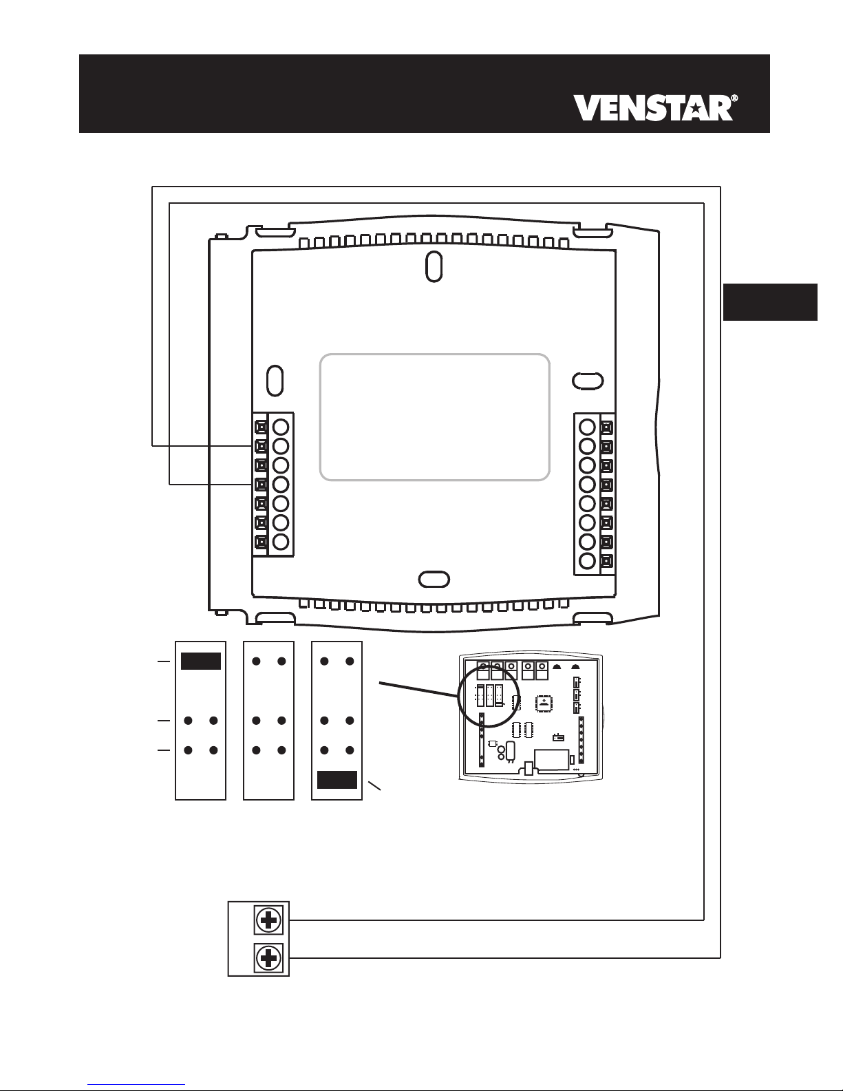
6 Wire, 1 Stage Cooling, 2 Stage Heat
Residential Heat Pump with O Reversing
Valve 1 Stage Cooling, with 2 stage Heat
5
(FAN)
ELEC
GAS
HP
GAS
B
O
24 vac common
HUM
DEHUM
MISC2
W3
MISC3 MISC2 MISC1
W1
Y1
G
R
C
W2
MISC1
RS2
MISC3
RS+5
RS1
RSGND
Y2
(MISC1
ONLY)
HUM
INSTALL HUMIDITY
MODULE WITH SENSING
ELEMENT OUTWARD
W1/O/B
Y1
G
MISC2
R
C
(FAN)
ELEC
GAS
HP
GAS
B
O
W2
MISC1
NO HUM
RS2
MISC3
RS+5
RS1
RSGND
6 Conductor 18 gauge
unshielded cable from the
thermostat to the equipment.
24 vac return
Fan Relay
Compressor Relay
Reversing Valve
2nd stage heat circuit
RC
G
Y1
O
W2
Page 5.4
Page 18

6 Wire, 1 Stage Cooling, 2 Stage Heat
Residential Heat Pump with b Reversing
Valve 1 Stage Cooling, with 2 stage Heat
5
(FAN)
ELEC
GAS
HP
GAS
B
O
24 vac common
HUM
DEHUM
MISC2
W3
W1
Y1
G
R
C
MISC3 MISC2 MISC1
W2
MISC1
RS2
MISC3
RS+5
RS1
RSGND
Y2
(MISC1
ONLY)
INSTALL HUMIDITY
MODULE WITH SENSING
ELEMENT OUTWARD
W1/O/B
Y1
G
MISC2
R
C
(FAN)
ELEC
GAS
HP
GAS
B
O
W2
MISC1
HUM
NO HUM
RS2
MISC3
RS+5
RS1
RSGND
6 Conductor 18 gauge
unshielded cable from the
thermostat to the equipment.
24 vac return
Fan Relay
Compressor Relay
Reversing Valve
2nd stage heat circuit
RC
G
Y1
b
W2
Page 5.5
Page 19
Adding a (MISC1) and (MISC3)2nd Stage of Cooling 3rd Stage of Heating
5
W3
HUM
DEHUM
W2
MISC1
RS2
MISC3
RS+5
RS1
RSGND
MISC3 MISC2 MISC1
Y2
(MISC1
ONLY)
HUM
DEHUM
MISC2
W3
MISC3 MISC2 MISC1
W1
Y1
G
R
C
W1/O/B
Y1
MISC2
Y2
(MISC1
ONLY)
INSTALL HUMIDITY
MODULE WITH SENSING
ELEMENT OUTWARD
G
R
C
HUM
(FAN)
ELEC
GAS
HP
GAS
B
O
W2
MISC1
NO HUM
RS2
MISC3
RS+5
RS1
RSGND
3rd Stage Heat
2nd Stage Cooling
W3
Y2
Page 5.6
Page 20
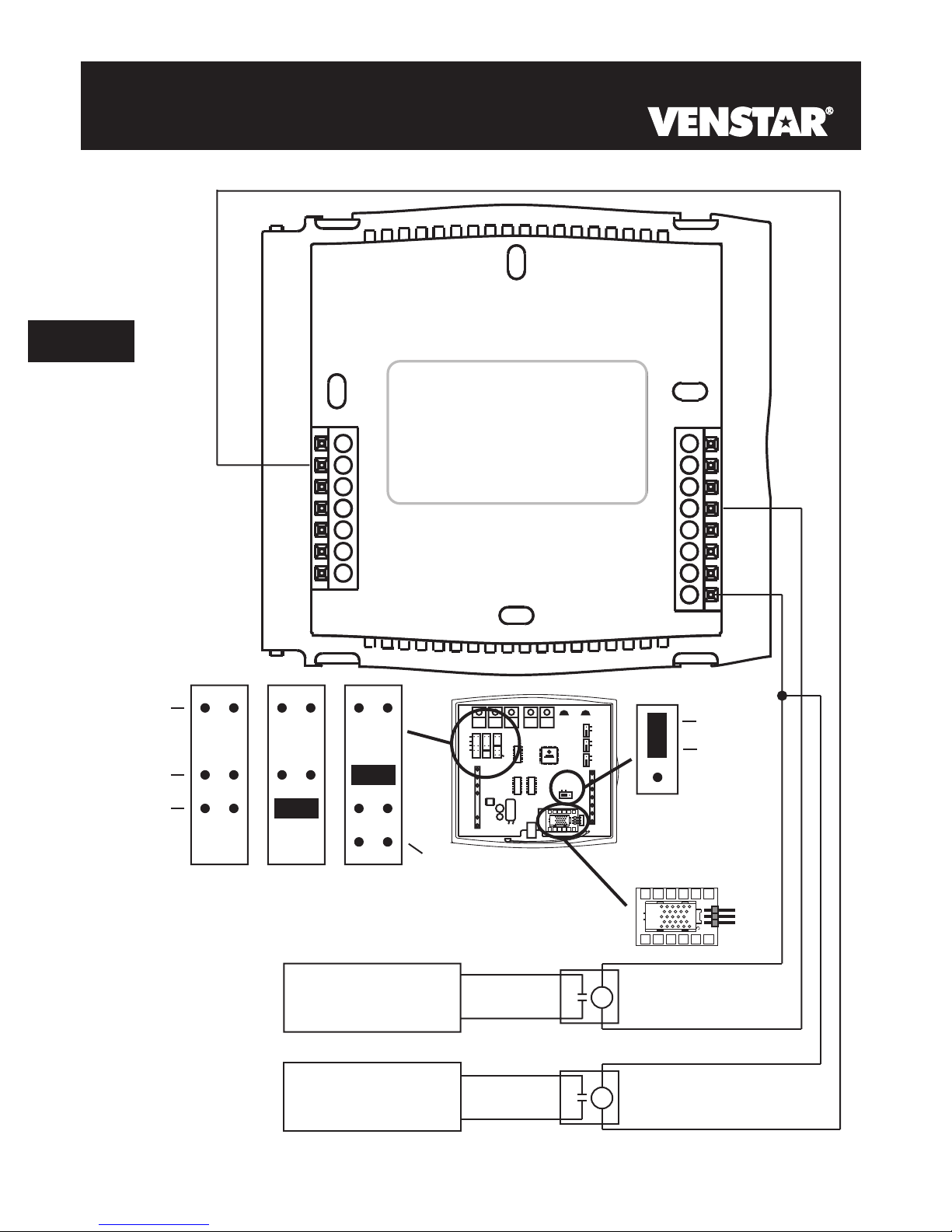
Adding a Humidification System (MISC1) and Dehumidification System (MISC2)*.
5
W3
HUM
DEHUM
MISC3 MISC2
W2
MISC1
RS2
MISC3
RS+5
RS1
RSGND
MISC1
Y2
(MISC1
ONLY)
PROG
HUM
DEHUM
MISC2
W3
MISC3 MISC2 MISC1
W1
Y1
G
R
C
W1/O/B
Y1
G
MISC2
R
C
(FAN)
ELEC
GAS
HP
2
4
INSTALL HUMIDITY
1
3
GAS
B
O
W2
MISC1
HUM
NO HUM
RS2
MISC3
RS+5
Z
8
6
X
RS1
1
RSGND
Y
579
Y2
(MISC1
ONLY)
MODULE WITH SENSING
ELEMENT OUTWARD
Humidity Module
(Sold Separately)
2
4
6
HUM
NO HUM
Z
8
X
1
Dehumidification
System
Humidification
System
* Requires Humidity Module.
Page 5.7
1
3
579
Y
Page 21

SECTION 6
Test Operation
Pm
I2:00
74
C
OOL
AUTO
H
EAT
72
Turn the power on to the Heating/Air Conditioning
system.
Pm
I2:00
74
C
OOL
AUTO
H
EAT
72
Press the MODE button repeatedly until the
HEAT icon appears on the display. Press
the
6
Up or Down buttons until the set temperature is
10 degrees above room temperature. The
furnace should turn on.
Pm
I2:00
74
C
OOL
AUTO
H
EAT
72
Press the MODE button repeatedly until the
COOL icon appears on the display.
Press the Up
or Down buttons until the set temperature is 10
degrees below room temperature. The air
conditioner should turn on. NOTE: Most
equipment has a time delay of 5 minutes between
cool cycles. This feature is defeatable on the
thermostat. Consult the Owner's Manual under
Setup, cycles per hour.
Pm
I2:00
74
C
OOL
AUTO
H
EAT
72
Press the UP button until the setpoint is equal to
the room temperature. Press the FAN
button to Fan On. The fan should turn on and run
continuously.
Page 6.1
Page 22
SECTION 7
Calibrating the Thermostat Sensors
Under normal circumstances it will not be necessary to adjust the
calibration of the temperature and humidity sensors. If calibration is
required, please contact a trained HVAC technician to correctly
perform the following procedure.
7
MODE
MODE
PRESS
TWICE
Place the thermostat in the
OFF mode.
Press
button. While holding the
MODE button, press and hold
the FAN button for 5 seconds.
FA N
Press the UP and buttons
at the same time twice. The
thermostat temperature will be
displayed and may be calibrated
using the UP or DOWN buttons.
All icons will appear on the
display.
THERMOSTAT SENSOR
and hold the MODE
DOWN
I2:00
Su
OFF
Pm
72
Program On
Am
I8:88
SuMoTuWeThFrSa
Service Filter
AUTO
OFFON
Morning
DayNight
Evening
FanOn
Pm
StartStop
DeHumidify
I88
Setup
H
I
88
Outside
Vacation
AUXH
L
O
88
CALIBRATE
C
OOL
EAT
REMOTE SENSOR
Press the MODE button once. The
remote sensor temperature will be
MODE
MODE
displayed and may be calibrated using the
UP or DOWN buttons. If a remote sensor
is not installed, only dashes will appear.
HUMIDITY SENSOR
Press the MODE button once. The
relative humidity at the thermostat will be
displayed and may be calibrated using the
UP or DOWN buttons.
After calibration is complete, press the MODE button once to return to
normal operation.
Page 7.1
Outside
CALIBRATE
CALIBRATE
Page 23
SECTION 8
TroubleShooting
Pm
I2:00
AUTO
SYMPTOM: The air conditioning does not attempt to
74
C
OOL
H
EAT
72
turn on.
CAUSE: The compressor timer lockout may prevent the
air conditioner from turning on, for a period of time.
REMEDY: Consult the Owner's Manual in the Setup
section to defeat the cycles per hour and
compressor timeguard.
8
Pm
I2:00
AUTO
SYMPTOM: The display is blank.
74
C
OOL
H
EAT
72
CAUSE: Lack of proper power.
REMEDY: Make sure power is turned on to the furnace
and that you have 24vac between R & W. If C is
used, 24vac between R & C.
Pm
I2:00
AUTO
SYMPTOM: The air conditioning does not attempt to
74
C
OOL
H
EAT
72
turn on.
CAUSE: The cooling setpoint is set too high.
REMEDY: Consult the Owner's Manual in the Setup
section to lower the cooling setpoint limit.
Pm
I2:00
AUTO
SYMPTOM: The heating does not attempt to turn on.
74
C
OOL
H
EAT
72
CAUSE: The heating setpoint is set too low.
REMEDY: Consult the Owner's Manual in the Setup
section to raise the heating setpoint limit.
Page 8.1
Page 24
TroubleShooting
Pm
I2:00
74
C
8
OOL
AUTO
H
EAT
72
Pm
I2:00
74
C
OOL
AUTO
H
EAT
72
SYMPTOM: When controlling a residential heat pump,
and asking for cooling, the heat comes on.
CAUSE: The thermostat reversing valve jumper is set
for “b”.
REMEDY: Set the reversing valve jumper for “O”. See
pages 5.4 and 5.5.
SYMPTOM: When calling for cooling, both the heat
and cool come on.
CAUSE: The thermostat equipment jumper is configured
for “HP” and the HVAC unit is a Gas/Electric.
REMEDY: Set the equipment jumper for “Gas”. See
pages 5.2 and 5.3.
Page 8.2
P/N 88-598
Rev. 1
Page 25

Digital
Digital
Thermostat
Thermostat
residential
THERMOSTAT
800
T1
7-DAY
7-DAY
PROGRAMMABLE
PROGRAMMABLE
Control up to 3 Heat &
2 Cool Stages
3 Configurable Outputs
Adjustable 2nd & 3rd Stage
Timers & Deadbands
Backlit Display & Button
Legends
Aux Heat Indicator
up to
up to
& 2-cool
& 2-cool
HEAT
COOL
Outdoor Sensor Ready
with High/Low Readouts
for the Day
Accepts Optional Humidity Module:
Controls Humidification and
Dehumidification
Accepts EZ Programmer
Accepts Optional IR Remote Control
Accepts Comfort Call
Phone Control Accessory
3-heat
3-heat
HEAT
PUMP
Use with most Air Conditioning & Heating Systems including: 1 or 2 Stage
Electric Cooling & 3 Stage Gas Heating, Heat Pump, Electric or Hydronic Heat.
OWNER’S
OWNER’S
MANUAL
MANUAL
Venstar Inc. 08/07
Page 26
CAUTION
Follow the Installation Instructions before proceeding.
Set the thermostat mode to “OFF” prior to changing
settings in setup or restoring Factory Defaults.
CAUTION
NEVER PUT MORE THAN ONE
JUMPER ON THE SAME MISC
JUMPER BLOCK!
THIS MAY DAMAGE YOUR
THERMOSTAT AND VOID
YOUR WARRANTY.
MISC3
OK
NOTE: Due to variations in environmental conditions, it is not
MISC3
always possible to achieve the desired humidification or
dehumidification setpoint.
This device complies with Part 15 of the FCC Rules. Operation is
subject to the following two conditions: (1) this device may not cause
harmful interference, and (2) this device must accept any interference
received, including interference that may cause undesired operation.
Thermostat T1800
Tested to Comply
c
with FCC Standards
C
F
4Z95
FOR HOME OR OFFICE USE
Page
i
Page 27
Timers and Deadbands
How to Use This Manual
The Table of Contents divides the thermostat features into sections
making it easier to quickly find information.
The first page of each section contains a more detailed Contents of each
section, such as the example page shown below.
SECTION 14
Header shows section #
Section 14 Contents:
Adjusting the Heat/Cool
Differential..............................14.2
Adjusting the Cycles
Per Hour..................................14.3
Adjusting the Deadband..........14.4
Adjusting the Minutes of
Run-Time Before the
Next Stage...............................14.6
Selecting 2nd Stage Turn
Off Temperature.....................14.7
and title of section
Section contents
14
Visible section tab
on the side of the
page
Section and page #
Page 14.1
In addition, this manual also has an Index to help you find any information
regarding this thermostat quickly.
Page
ii
Page 28

Glossary of Terms
Auto-Changeover: A mode in which the thermostat will turn on
the heating or cooling based on room temperature demand.
Configurable Output Jumper: Using jumpers on the thermostat
you can configure the MISC1, MISC2, and MISC3 terminals to
operate with regards to humidification, dehumidification, 2nd
stage cooling, 3rd stage heating, and a programmable output.
Cool Setpoint: The warmest temperature that the space should
rise to before cooling is turned on (without regards to
deadband).
Deadband: The number of degrees the thermostat will wait, once
setpoint has been reached, before energizing heating or cooling.
Dehumidify: To reduce the amount of moisture in the air.
Differential: The forced temperature difference between the
heat setpoint and the cool setpoint.
Heat Setpoint: The coolest temperature that the space should
drop to before heating is turned on (without regards to
deadband).
Humidify: To increase the amount of moisture in the air.
Icon: The word or symbol that appears on the thermostat
display.
Mode: The current operating condition of the thermostat (i.e. Off,
Heat, Cool, Auto, Program On).
Non-Programmable Thermostat: A thermostat that does not
have the capability of running the Time Period Programming.
Programmable Thermostat: A thermostat that has the capability
of running the Time Period Programming.
Temperature Swing: Same as Deadband.
Time Period Programming: A program that allows the
thermostat to automatically adjust the heat setpoint and/or the
cool setpoint based on the time of day.
Page
iii
Page 29

Table of Contents
Getting to Know Your
Thermostat
Quick Start
Setting Clock and Day
Basic Operation
Viewing Temperature
and Humidity Sensors
Programming the
Daily Schedule
Programming the
Fan Operation
Thermostat Display
Options
Humidification
Dehumidification
Viewing Equipment
Run-Times
Electric Heat and
Heat Pump Operation
1
2
3
4
5
6
7
8
9
10
11
12
Timers and Deadbands
Programming Remote
Sensor Operation
Energy Save
Operation
Programming the Run-
Time Alerts
Programming the
Vacation Mode
Configuring the MISC
Outputs
Factory Defaults and
Calibration
Accessories
Advanced Setup Table
13
14
15
16
17
18
19
20
21
Page iv
Page 30

SECTION 1
Getting to Know Your Thermostat
1
Section 1 Contents:
Front Panel Buttons.....................1.2
Display Features...........................1.3
Page 1.1
Page 31

Front Panel
HUMIDITY
PROGRAM SET CLOCK
FAN
MODE
VACATION
OUTDOOR
1
Backlit LCD Display
Pm
I2:00
Mo
AUTO
74
C
H
OOL
EAT
72
Heat or Cool Demand Indicator
Red = Heat, Green = Cool
Mode
Button
Warmer Button sometimes referred
(glows red)
to as the UP button
[]
Cooler Button sometimes refer-
(glows blue)
DOWN button
red to as the
[]
QUICK RELEASE FOR
ACCESSORY PORT
(pg. 20.1)
FAN
PLATINUM
COMMERCIAL PROGRAMMABLE THERMOSTAT
I2:00
Su
AUTO
OUTDOOR
eries
Pm
HUMIDITY
Page 1.2
74
C
H
72
OOL
EAT
PROGRAM
SET CLOCK
VACATION
Page 32

Display Features
1
1
1
D
Am
I8:88
SuMoTuWeThFrSa
Service Filter
UV Light
AUTO
OFFON
Morning
DayNight
Evening
FanOn
Mode Indicators Selects the operational mode of the equipment.
HEAT - Indicates the heating mode.
COOL - Indicates the air conditioning mode.
AUTO - Indicates the system will automatically changeover
between heat and cool modes as the temperature varies.
OFF - Indicates heating and cooling is turned off.
PROGRAM ON - Indicates the time period program is enabled to
run.
Clock with Day of the Week - Section 3
Indicates the current time and day. This clock is also used to program
the time period schedule.
Pm
I88
Section 4
Program On
StartStop
DeHumidify
Setup
A
L
H
I
88
C
OOL
Outside
Vacation
UXHEAT
O
88
Room Temperature Display - Section 5
Indicates the current room temperature and displays the outdoor
temperature when selected.
Desired Set Temperature - Section 4/5
Indicates desired room temperature(s). Also displays the highest
and lowest temperatures for the day.
Outside icon - Section 5
Indicates the temperature displayed is from the optional outdoor
sensor.
Page 1.3
Page 33

Display Features
1
Am
I8:88
SuMoTuWeThFrSa
Service Filter
UV Light
AUTO
OFFON
Morning
DayNight
Evening
FanOn
Morning, Day, Evening & Night icons - Section 6
Indicates the day part of the time period program.
Setup icon Indicates the thermostat is in the setup mode.
Sections 6-17
Pm
I88
Program On
StartStop
DeHumidify
Setup
A
L
H
I
88
C
Outside
Vacation
UXHEAT
O
88
OOL
Fan On icon -
Indicates constant, continuous fan operation.
When Fan On is not lit - indicates the fan will only operate when
necessary to heat or to cool.
Service Filter icon Appears when the filter should be serviced under normal conditions.
Adjustable from 0 - 1950 hours of blower operation.
icon Indicates the keypad has been locked.
StartStop icon Appears when programming timer functions.
UV Light icon Appears when the UV bulb should be serviced under normal
conditions. Adjustable from 0 - 1990 days of operation.
Section 7
Section 8
Section 6
Section 19
Section 16
Page 1.4
Page 34

Display Features
1
Am
I8:88
SuMoTuWeThFrSa
Service Filter
UV Light
AUTO
OFFON
Morning
DayNight
Evening
FanOn
Vacation icon -
Indicates the thermostat has Vacation setpoints in use.
Pm
I88
Section 17
Program On
StartStop
DeHumidify
Setup
A
L
H
I
88
C
OOL
Outside
Vacation
UXHEAT
O
88
AuxHeat icon - Page 13.4
Indicates 2nd stage electric strip heat is being used when the
thermostat is programmed for Heat Pump operation.
Humidify/DeHumidify icon Indicates the system is currently humidifying/dehumidifying the air.
Lo icon Indicates the lowest recorded outdoor temperature for the day.
Hi icon Indicates the highest recorded outdoor temperature for the day.
Section 5
Section 5
Sections 9/10
Page 1.5
Page 35

SECTION 2
Quick Start
Section 2 Contents:
Setting the Clock and Day...........2.2
Selecting the Heat or Cool
Mode............................................2.3
2
Selecting Your Desired
Temperature................................2.4
Using the Fan Button...................2.4
Note: Following the instructions in this section will allow you to
operate your thermostat using the factory default settings. These
settings are depicted in the illustrations throughout this manual.
Page 2.1
Page 36

Setting the Clock
Setting the Day
GRAM SET CLOCK
MO
VACATION
GRAM SET CLOCK
MO
VACATION
2
Press the SET
CLOCK button
During Setup & Programming:
Pressing the UP or DOWN
buttons will modify the flashing
I2:00
Am
Mo
Press the SET
CLOCK button
Setup
Setup
I
2
selection.
To adjust the
Clock or Day use
Press
MODE
buttons.
To adjust the time by
hours press and hold
the FAN button while
pressing the UP or
DOWN buttons.
to return to
normal operation.
Page 2.2
Page 37

Selecting the Heat or Cool Mode
Select Mode by Pressing the MODE Button
2
Heating Only
The HEAT setting indicates the
temperature the room has to
reach before the furnace will
turn on to heat the room.
Cooling Only
The COOL setting indicates the
temperature the room has to
reach before the air conditioner
will turn on to cool the room.
Heating or Cooling
AUTO will automatically select
heat or cool based on room
temperature demand.
I2:00
Su
I2:00
Su
I2:00
Su
AUTO
Pm
70
Pm
70
Pm
70
H
EAT
68
76
C
OOL
76
C
OOL
H
EAT
68
Press
MODE
Press
MODE
Press
Time Schedule for
Heating or Cooling
The Program On setting will
activate the time period
programming for the cooling
or heating setpoint ONLY
(Morning, Day, Evening
& Night Periods).
Off
OFF indicates both heating
and air conditioning
systems are turned off.
Program On
I2:00
Su
Day
Pm
70
I2:00
Su
OFF
Pm
70
Page 2.3
76
C
OOL
H
EAT
68
MODE
Press
MODE
Page 38

Selecting Your Desired Temperature (adjusting the setpoints)
Using the Fan Button
2
AUTO OR PROGRAM MODE
Pressing the UP or DOWN buttons in Auto or Program mode
will adjust both the heat and cool set temperatures
simultaneously.
I2:00
Su
AUTO
HEAT OR COOL MODE
Pressing the UP or DOWN buttons in Heat or Cool mode will
adjust only the heat or cool set temperature.
Pm
70
76
C
OOL
H
EAT
68
Adjust the desired
set temperature with the
buttons.
I2:00
Su
Pm
70
I2:00
Su
AUTO
FanOn
Pm
70
76
C
OOL
76
C
OOL
H
EAT
68
Adjust the desired
set temperature with the
buttons.
Press
FAN
Fan On indicates constant fan
operation. You may turn the fan
on even if the thermostat is in the
Off mode. Pressing the FAN button
toggles this feature on or off.
Page 2.4
Page 39

SECTION 3
Setting the Clock and Day
Section 3 Contents:
Setting the Clock..........................3.2
Setting the Day.............................3.2
3
Note: During setup & programming pressing the UP or DOWN
buttons will modify the flashing selection.
Page 3.1
Page 40

Setting the Clock
Setting the Day
GRAM SET CLOCK
MO
VACATION
GRAM SET CLOCK
MO
VACATION
3
Press the SET
CLOCK button
During Setup & Programming:
Pressing the UP or DOWN
buttons will modify the flashing
selection.
I2:00
Am
Mo
Press the SET
CLOCK button
Setup
Setup
I
2
To adjust the
Clock or Day use
Press
MODE
buttons.
To adjust the time by
hours press and hold
the FAN button while
pressing the UP or
DOWN buttons.
to return to
normal operation.
Page 3.2
Page 41

SECTION 4
Basic Operation
Section 4 Contents:
Programmable or Non-
Programmable Thermostat........4.2
4
Manual or Auto-Changeover
Thermostat..................................4.3
Selecting the Operating Mode....4.4
Selecting Your Desired
Temperature................................4.8
Note: During setup & programming pressing the UP or DOWN
buttons will modify the flashing selection.
Page 4.1
Page 42

Programmable or Non-Programmable
Thermostat
When the very simplest operation is desired, this thermostat
4
If ‘NO’ is selected, the thermostat will lockout the Program On screen;
only the Off, Heat, Cool, and Auto screens may be accessed by
pressing the MODE button.
Select ‘YES’ if you would like your thermostat to be programmable,
then the Program mode will be accessible through the use of the
MODE button.
PROGRAM
may be configured to be non-programmable, with or without
Auto-Changeover. Follow the step below.
Note: Press the MODE
button momentarily
MODE
Press the MODE button. While holding
the MODE, press the PROGRAM
button to enter Setup screens.
to move through the
setup screens. Press
and hold the
button to move backwards th rough th e
setup screens.
MODE
YES
Select Yes if you would like
the thermostat to be programmable or No for non-programmable.
NO
Press the PROGRAM button to leave the Setup screens. If no buttons are
pressed, the display will leave the setup screens after 30 seconds.
Program On
Setup
i
PROGRAM
Page 4.2
Press
Page 43

Manual or Auto-Changeover
Thermostat
When the very simplest operation is desired, this thermostat may
be configured to be a manual heat and cool thermostat, with or
4
without time period programmability. Follow the step below.
The thermostat may be programmed to function as a Heat Only or
Cool Only thermostat by selecting ‘NO’ in the setup screen below.
This will lockout the Auto-Changeover screen and only allow the Off,
Heat, Cool, and Program On screens to be accessed.
MODE
PROGRAM
MODE
YES
Select Yes if you would
like the thermostat to
be Auto-Changeover or
No for a Heat Only and
Cool Only Thermostat.
NO
Press the MODE button. While holding
the MODE, press the PROGRAM
button to enter Setup screens.
Press the MODE button repeatedly
until this setup screen appears.
Setup
AUTO
Note: Press the MODE
button momentarily
to move through the
setup screens. Press
and hold the
button to move backwards through the
setup screens.
2
Press
PROGRAM
MODE
Press the PROGRAM button to leave the Setup screens. If no buttons are
pressed, the display will leave the setup screens after 30 seconds.
Page 4.3
Page 44

Operating Mode when the Thermostat
is Configured to be:
NON-PROGRAMMABLE WITH MANUAL-CHANGEOVER - If the
thermostat is configured to be a non-programmable thermostat with
4
Manual-Changeover, the following screens will be available by
pressing the MODE button.
Select the Mode by Pressing the MODE Button
Heating Only
The HEAT setting indicates the
temperature the room has to
reach before the furnace will
turn on to heat the room.
Cooling Only
The COOL setting indicates the
temperature the room has to
reach before the air conditioner
will turn on to cool the room.
Off
OFF indicates both heating
and air conditioning
systems are turned off.
I2:00
Su
I2:00
Su
I2:00
Su
OFF
Pm
70
Pm
70
Pm
H
EAT
68
76
C
OOL
Press
MODE
Press
MODE
70
Page 4.4
Page 45

Operating Mode when the Thermostat
is Configured to be:
NON-PROGRAMMABLE WITH AUTO-CHANGEOVER - If the
thermostat is configured to be a non-programmable thermostat
with Auto-Changeover, the following screens will be available by
pressing the MODE button
Select the Mode by Pressing the MODE Button
4
Heating Only
The HEAT setting indicates the
temperature the room has to
reach before the furnace will
turn on to heat the room.
Cooling Only
The COOL setting indicates the
temperature the room has to
reach before the air conditioner
will turn on to cool the room.
Heating or Cooling
AUTO will automatically select
heat or cool based on room
temperature demand.
I2:00
Su
I2:00
Su
I2:00
Su
AUTO
Pm
70
Pm
70
Pm
H
EAT
68
76
C
OOL
76
C
OOL
H
EAT
Press
MODE
Press
MODE
Off
OFF indicates both heating
and air conditioning
systems are turned off.
70
I2:00
Su
OFF
Pm
70
Page 4.5
68
Press
MODE
Page 46

Operating Mode when the Thermostat
is Configured to be:
PROGRAMMABLE WITH MANUAL-CHANGEOVER - If the thermostat is
configured to be a programmable thermostat with Manual-Changeover, the
following screens will be available by pressing the MODE button.
4
Select the Mode by Pressing the MODE Button
Heating Only
The HEAT setting indicates the
temperature the room has to
reach before the furnace will
turn on to heat the room.
Cooling Only
The COOL setting indicates the
temperature the room has to
reach before the air conditioner
will turn on to cool the room.
Time Schedule for
Heating Only
The HEAT Program On setting
will activate the time period
program for the heating
setpoint ONLY (Morning, Day,
Evening & Night Periods).
Time Schedule for
Cooling Only
The COOL Program On setting
will activate the time period
program for the cooling
setpoint ONLY (Morning, Day,
Evening & Night Periods).
Off
OFF indicates both heating
and air conditioning
systems are turned off.
I2:00
Su
I2:00
Su
I2:00
Su
Day
I2:00
Su
Day
I2:00
Su
OFF
Pm
70
Pm
70
Program On
Pm
70
Program On
Pm
70
Pm
H
EAT
68
76
C
OOL
H
EAT
68
76
C
OOL
Press
MODE
Press
MODE
Press
MODE
Press
MODE
70
Page 4.6
Page 47

Operating Mode when the Thermostat
is Configured to be:
PROGRAMMABLE WITH AUTO-CHANGEOVER - If the thermostat is
configured to be a programmable thermostat with Auto-Changeover,
the following screens will be available by pressing the MODE button.
Select the Mode by Pressing the MODE Button
4
Heating Only
The HEAT setting indicates the
temperature the room has to
reach before the furnace will
turn on to heat the room.
Cooling Only
The COOL setting indicates the
temperature the room has to
reach before the air conditioner
will turn on to cool the room.
Heating or Cooling
AUTO will automatically select
heat or cool based on room
temperature demand.
Time Schedule for
Heating or Cooling
The Program On setting will
activate the time period
programming for the cooling
or heating setpoint ONLY
(Morning, Day, Evening
& Night Periods).
Off
OFF indicates both heating
and air conditioning
systems are turned off.
I2:00
Su
I2:00
Su
I2:00
Su
AUTO
I2:00
Su
Day
I2:00
Su
OFF
Pm
70
Pm
70
Pm
70
Program On
Pm
70
Pm
H
EAT
68
76
C
OOL
76
C
OOL
H
EAT
68
76
C
OOL
H
EAT
68
Press
MODE
Press
MODE
Press
MODE
Press
MODE
70
Page 4.7
Page 48

Selecting Your Desired Temperature (adjusting setpoints)
AUTO OR PROGRAM MODE
Pressing the UP or DOWN buttons in Auto or Program
4
modes will adjust both the heat and cool set temperatures
simultaneously. For more information on this see page 13.2.
Adjust the desired
I2:00
Su
AUTO
HEAT OR COOL MODE
Pressing the UP or DOWN buttons in Heat or Cool modes will
adjust only the heat or cool set temperature.
Pm
70
76
C
OOL
H
EAT
68
set temperature with the
buttons.
I2:00
Su
Pm
70
76
C
OOL
Page 4.8
Adjust the desired
set temperature with the
buttons.
Page 49

SECTION 5
Viewing the Temperature and Humidity Sensors
Section 5 Contents:
Viewing the Outdoor
Temperature..............................5.2
5
Viewing the Indoor
Humidity....................................5.3
Page 5.1
Page 50

Viewing the Outdoor Temperature
HUM
N
OUTDOOR
HUM
N
OUTDOOR
This requires an outdoor sensor (optional accessory) to be installed
(see page 14.2 for wiring instructions). To read the temperature
from the outdoor sensor, press the OUTDOOR button. The display
will then show the current outdoor temperature along with the
highest and lowest temperatures for the day. The day starts at
5
12:00 am.
The highest and lowest
temperatures for the day
will be displayed along
with the current outdoor
temperature. This
reading is from the sensor
connected to RS2.
This reading is from the
sensor connected to
RS1.
Press the OUTDOOR
button.
83
HI
92
Outside
LO
68
High temperature
for the day.
Current outdoor
temperature.
Low temperature
for the day.
Press
MODE
Press the OUTDOOR
button to return to
normal operation.
Note: If no sensors are connected 2 dashes [- -] will appear on the display.
78
Page 5.2
Page 51

Viewing the Indoor Humidity
Requires the Humidity Module (optional accessory) to be
installed. To display the current humidity at the thermostat,
press the HUMIDITY button of the thermostat. The display will
then show the current indoor humidity along with the
humidification setpoint (Section 9).
Note: The humidity reading will not appear unless the Humidity
Module has been installed. If a sensor has not been installed
dashes will appear in place of the humidity reading.
5
HUMIDITY
Current Room Humidity
To view the indoor humidity
reading, press the
HUMIDITY button
40
Humidify
Setup
I
0
Press the HUMIDITY button
again to return the display
to normal operation.
Press
HUMIDITY
NOTE: Due to variations in environmental conditions, it is not always possible
to achieve the desired humidification or dehumidification setpoint.
Page 5.3
Page 52

SECTION 6
Programming the Daily Schedule
Section 6 Contents:
6
Programming a Daily
Schedule...................................6.2
Page 6.1
Page 53

Programming a Daily Schedule
Press
PROGRAM
Press the PROGRAM button to enter time period programming.
Use the Programming Worksheet on the back cover
to help with this section.
Select the day of week
(Mo - Su)
Adjust the start time
for Morning.
Adjust the cooling
setpoint for Morning.
Mo
6:00
Mo
Morning
6:00
Mo
Am
Am
Start
78
C
OOL
6
Press
MODE
Press
MODE
(35 - 99 )
Adjust the heating
setpoint for Morning.
(35 - 99 )
Morning
6:00
Mo
Morning
Am
Page 6.2
78
C
OOL
H
EAT
70
Continued
Press
MODE
Press
MODE
Page 54

Adjust the start time
for Day.
8:00
Mo
Day
Am
Start
Press
MODE
6
Adjust the cooling
setpoint for Day.
(35 - 99 )
Adjust the heating
setpoint for Day.
(35 - 99 )
Adjust the start time
for Evening.
8:00
Mo
Day
8:00
Mo
Day
6:00
Mo
Am
Am
Pm
Start
85
C
OOL
85
C
OOL
H
EAT
62
Press
MODE
Press
MODE
Adjust the cooling
setpoint for Evening.
(35 - 99 )
Evening
6:00
Mo
Evening
Pm
Page 6.3
78
C
Continued
Press
MODE
OOL
Press
MODE
Page 55

Adjust the heating
setpoint for Evening.
(35 - 99 )
6:00
Mo
Evening
Pm
78
C
OOL
H
EAT
70
Press
MODE
6
Adjust the start time
for Night.
Adjust the cooling
setpoint for Night.
(35 - 99 )
Adjust the heating
setpoint for Night
(35 - 99 )
I0:00
Mo
Night
I0:00
Mo
Night
I0:00
Mo
Night
Pm
Pm
Pm
Start
82
C
OOL
82
C
OOL
H
EAT
62
Press
MODE
Press
MODE
Press
MODE
Continued
Page 6.4
Page 56

6
The copy command becomes available after
programming the entire previous day.
Yes
Tu
Select Yes to copy the
previous day’s program
to this day displayed.
No
If Yes is selected:
Selecting Yes, then pressing mode will copy the
Press
MODE
If No is selected, as in previous steps, flashing prompts for input will appear for
the four time periods for the next day.
Press
PROGRAM
After programming for all seven days is complete, press the PROGRAM button to
leave the Setup screens. If no buttons are pressed, the display will leave the setup
screens after 30 seconds.
previous day’s program. If yes is selected again,
or each time, this routine will repeat.
If No is selected:
Press
MODE
Page 6.5
Page 57

SECTION 7
Programming the Fan Operation
Section 7 Contents:
Using the Fan Button.................7.2
Programming the Fan................7.3
Setting the Fan-Off Time
Delay..........................................7.4
7
Page 7.1
Page 58

Using the Fan Button
When the fan is set for automatic operation it will energize any time
there is a call for heating or cooling, otherwise the fan will remain off.
Pressing the FAN button will energize the fan and display the FanOn
icon on the thermostat display. To operate the fan in the automatic
mode, press the FAN button again and the FanOn icon will disappear.
Press
7
FAN
I2:00
Su
AUTO
FanOn
Pm
70
76
C
OOL
H
EAT
68
Fan On indicates constant fan
operation. You may turn the fan
on even if the thermostat is in the
Off mode. Pressing the FAN button
toggles this feature on or off.
Page 7.2
Page 59

Programming the Fan
This timer will start the fan at the top of each hour and the fan will run
for the number of minutes selected in step #3. Steps 4 & 5 restrict the
hours during which the programmable fan may operate; step #4 is the
start time and step #5 is the stop time. Selecting the same start and
stop times will cause the fan to operate 24 hours a day.
MODE
PROGRAM
MODE
Press the MODE button. While holding
the MODE, press the PROGRAM
button to enter Setup screens.
Press the MODE button repeatedly
until this setup screen appears.
Adjust the Programmable
Fan timer.
0 - 60 minutes.
0:00 = off
Adjust the Programmable
Fan start time. (step 4
appears only if step 3
is not 0:00)
0:00
FanOn
7:00
Am
Start
Setup
Setup
3
4
7
Note: Press the MODE
button momentarily
to move through the
setup screens. Press
and hold the
button to move backwards through the
setup screens.
MODE
Press
MODE
Press
Adjust the Programmable
Fan stop time. (step 5
appears only if step 3
is not 0:00)
Press the PROGRAM button to leave the Setup screens. If no buttons are
pressed, the display will leave the setup screens after 30 seconds.
FanOn
9:00
OFF
FanOn
Pm
Page 7.3
MODE
Setup
Stop
5
Press
PROGRAM
Page 60

Setting the Fan-Off Time Delay
To increase the cooling efficiency of your unit, the thermostat may be
programmed to continue running the fan after a call for cooling has
been satisfied. This delay may be set for 30, 60, or 90 seconds. If
the Fan Off Delay is set for zero seconds, the fan will not energize
after a call for cooling has been satisfied.
7
MODE
PROGRAM
MODE
Press the PROGRAM button to leave the Setup screens. If no buttons are
Press the MODE button. While holding
the MODE, press the PROGRAM
button to enter Setup screens.
Press the MODE button repeatedly
until this setup screen appears.
Setup
Note: Press the MODE
button momentarily
to move through the
setup screens. Press
and hold the
button to move backwards through the
setup screens.
:00
6
Set the Fan Off Delay
to 0, 30, 60, or 90
seconds.
FanOn
pressed, the display will leave the setup screens after 30 seconds.
MODE
Press
PROGRAM
Page 7.4
Page 61

SECTION 8
Thermostat Display Options
Section 8 Contents:
Turning On/Off the
Backlight...................................8.2
Programming the Thermostat
8
to Display Temperature in
Fahrenheit or Celsius..............8.2
Locking/Unlocking the
Keypad......................................8.3
Page 8.1
Page 62

T
Turning On/Off the Backlight
Programming the Thermostat to Display
Temperature in Fahrenheit or Celsius
MODE
PROGRAM
MODE
Press the MODE button. While holding
the MODE, press the PROGRAM
button to enter Setup screens.
Press the MODE button repeatedly
until this setup screen appears.
8
Setup
Select backlight operation:
AUTO - Light from 6pm to
6am nightly.
ON - Light continuously.
OFF - Light for 8 seconds
after a button press.
AUTO
Note: Press the MODE
button momentarily
to move through the
setup screens. Press
and hold the
button to move backwards through the
setup screens.
MODE
7
Press
MODE
C
Select thermostat
operation in degrees
Fahrenheit or Celsius.
F
Press the PROGRAM button to leave the Setup screens. If no buttons are
pressed, the display will leave the setup screens after 30 seconds.
Page 8.2
Setup
f
8
Press
PROGRAM
Page 63

Locking/Unlocking the Keypad
To prevent unauthorized use of the thermostat, the front panel
buttons may be disabled. To disable, or ‘lock’ the keypad, press
and hold the MODE button. While holding the MODE button,
press the UP and DOWN buttons together. The icon will
appear on the display, then release the buttons.
Press all three
buttons in the order
outlined above for
keypad lockout
I2:00
Su
AUTO
MODE
Pm
65
85
C
H
55
OOL
EAT
8
To unlock the keypad,
holding the MODE button, press the UP and DOWN buttons
together. The icon will disappear from the display, then
release the buttons.
press and hold the MODE button. While
Page 8.3
Page 64

SECTION 9
Humidification
Section 9 Contents:
Installing the Humidity
Module.......................................9.2
Configuring a Thermostat Output
Jumper for Humidity
Operation...................................9.3
9
Adjusting the Humidification
Setpoint.....................................9.4
Energizing the Fan with
Humidification..........................9.5
NOTE: The humidification functions described in this section will
only be available if a Humidity Module has been properly installed.
Disclaimer:
The manufacturer of this thermostat cannot be liable for
misinstallation, improper connection or improper programming of
the humidity functions of this thermostat that may result in water
damage or mold growth.
Additionally, the manufacturer of this thermostat is not responsible
for the fitness of the humidifier and/or installation of said humidifier
connected to this thermostat. Furthermore, the maintenance of the
humidifier components, including but not limited to, the filters and
pads are not the responsibility of the thermostat manufacturer.
The Humidifier Service icon is only a suggestive reminder and
should not take the place of the humidifier manufacturer’s
required maintenance requirements and schedule.
Page 9.1
Page 65

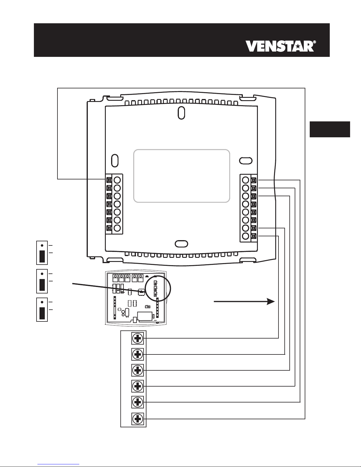
Installing the Humidity Module
To install the Humidity Module the thermostat must be detached
from the back plate. Plug the Humidity Module into the Humidity
Module connector as shown in Figure 2 below. Follow the detailed
instructions included with the Humidity Module accessory. Once the
Humidity Module has been installed, you must adjust the Humidity
jumper setting to HUM as shown in Figure 1 below. This will allow
you to access the humidification and dehumidification setup steps.
Back of T1800
For proper humidity operation, this
jumper must be set for HUM.
Figure 1
HUM
9
DEHUM
W3
HUM
W1
MISC2
MISC3 MISC2 MISC1
Y1
G
R
C
Y2
(MISC1
ONLY)
(FAN)
ELEC
GAS
HP
GAS
B
O
W2
HUM
NO HUM
2
8
4
6
INSTALL HUMIDITY
MODULE WITH SENSING
ELEMENT OUTWARD
1
3
579
MISC1
RS2
MISC3
RS+5
Z
X
Rs1
1
RSGND
Y
Figure 2
Humidity Module
Thermostat Circuit
Board.
OR
NO HUM
Install the Humidity Module
(see Humidity Module Instruction
Sheet for more detailed information).
Humidity Module
Plug located on
the Thermostat
Circuit Board.
Page 9.2
Page 66

Setting a Thermostat Output Jumper
for Humidity Operation
To control a MISC output for humidification,
install the Humidity
Module and place the Humidity Jumper on HUM (see previous page).
Then place the MISC1, MISC2, or MISC3 jumper on the terminal
labeled HUM (see diagram below). This will supply 24VAC to the
selected MISC terminal based on the humidification programming in
the following pages. Only one of the three outputs (MISC1, MISC2,
or MISC3) is required to have this jumper. For more information
regarding the MISC1, MISC2, and MISC3 outputs, please see
section 18.
9
In the diagram below, the MISC3 jumper
has been set for HUM (humidify) operation.
(FAN)
ELEC
GAS
HP
GAS
B
O
W2
MISC1
RS2
MISC3
RS+5
Z
X
1
Rs1
RSGND
Y
HUM
DEHUM
HUM
DEHUM
MISC2
W3
W1
Y1
G
C
MISC3 MISC2 MISC1
R
(MISC1
Y2
ONLY)
HUM
NO HUM
2
8
4
6
INSTALL HUMIDITY
MODULE WITH SENSING
ELEMENT OUTWARD
1
3
579
W3
MISC3 MISC2 MISC1
(MISC1
ONLY)
Y2
MISC3
MISC3
OK
IMPORTANT CAUTION
NEVER PUT MORE THAN ONE JUMPER
ON THE SAME MISC JUMPER BLOCK!
THIS MAY DAMAGE YOUR THERMOSTAT
AND VOID YOUR WARRANTY
Page 9.3
Page 67

Adjusting the Humidification Setpoint
If your HVAC unit is equipped with a humidification system and the
Humidity Module has been installed, the thermostat will provide power
to the appropriate terminal on the backplate of the thermostat when
the humidity in the home falls below the setpoint you have chosen.
The value for this setpoint ranges from 0% to 60%.
NOTE: Due to variations in environmental conditions, it is not always possible
to achieve the desired humidification or dehumidification setpoint.
HUMIDITY
Press the HUMIDITY
button to enter the
Humidity Setup screen.
NOTE: Each step # is located at
the top right corner of the
display for easy reference.
9
Current Room Humidity
Adjust the desired
humidification setpoint
(0%-60%)
40
Humidify
0
Press the HUMIDITY button to leave the
Humidity Control screens (if no buttons are
pressed, the display will leave the Humidity
Control screens after 30 seconds).
Setup
I
Press
HUMIDITY
Humidification Notes: Press the button to set the humidity
setpoint to 0% for no humidification operation.
You cannot set the dehumidify setpoint any lower than the humidify setpoint; a
5% differential is forced between the humidify and dehumidify setpoints.
Page 9.4
Page 68

E
Energizing the Fan with Humidification
Selecting YES for this setup step will enable the Fan to automatically
energize any time there is a call for humidity. The HUM/NO HUM
jumper must be set for HUM in order to access this setup step. If NO
is selected, the Fan will not automatically energize on a call for
humidity.
MODE
Press the MODE button. While holding
the MODE, press the PROGRAM
PROGRAM
9
MODE
Step 9 only appears if the HUM/NO HUM jumper is
set for HUM (see page 9.2) and the Humidification
setpoint is not 0% (see page 9.4).
Press the PROGRAM button to leave the Setup screens. If no buttons are
button to enter Setup screens.
Press the MODE button repeatedly
until this setup screen appears.
Select fan operation with
a call for humidification:
NO: Fan will not energize
when there is a call
for humidification.
YES: Fan will energize
when there is a call
for humidification.
pressed, the display will leave the setup screens after 30 seconds.
FanOn
Humidify
Setup
Note: Press the MODE
button momentarily
to move through the
setup screens. Press
and hold the
button to move backwards through the
setup screens.
PROGRAM
MODE
Press
Page 9.5
Page 69

SECTION 10
Dehumidification
Section 10 Contents:
Configuring a Thermostat Output
Jumper for Dehumidification
Operation................................10.2
Adjusting the Dehumidification
10
Setpoint...................................10.3
Using Your Air Conditioner
to Dehumidify.........................10.4
Using the DEHUM
Terminal..................................10.5
NOTE: The dehumidification functions described in this section will
only be available if a Humidity Module has been properly installed.
For instructions on installing the Humidity Module please see page 9.2.
Page 10.1
Page 70

Setting a Thermostat Jumper for
Dehumidification Operation
To control a MISC output for dehumidification,
install the Humidity
Module and place the Humidity Jumper on HUM (see page 9.2).
Then place the MISC1, MISC2, or MISC3 jumper on the terminal
labeled DEHUM (see diagram below). This will supply 24VAC to the
selected MISC terminal based on the dehumidification programming
in the following pages. Only one of the three outputs (MISC1, MISC2,
or MISC3) is required to have a jumper. For more information
regarding the MISC1, MISC2, and MISC3 outputs, please see
section 18.
In the diagram below, the MISC2 jumper has
10
been set for DEHUM (dehumidification) operation.
(FAN)
DEHUM
MISC2
W3
HUM
W1
MISC3 MISC2 MISC1
Y1
G
R
C
(MISC1
ONLY)
ELEC
GAS
HP
GAS
Y2
HUM
NO HUM
2
8
4
6
INSTALL HUMIDITY
MODULE WITH SENSING
ELEMENT OUTWARD
1
3
579
B
O
W2
MISC1
RS2
MISC3
RS+5
Z
X
1
Rs1
RSGND
Y
W3
HUM
DEHUM
MISC3 MISC2 MISC1
(MISC1
ONLY)
Y2
MISC3
MISC3
OK
IMPORTANT CAUTION
NEVER PUT MORE THAN ONE JUMPER
ON THE SAME MISC JUMPER BLOCK!
THIS MAY DAMAGE YOUR THERMOSTAT
AND VOID YOUR WARRANTY
Page 10.2
Page 71

Adjusting the Dehumidification Setpoint
Dehum Terminal: If a MISC terminal selected for DEHUM operation
(see page 10.2) then the thermostat will provide power to this terminal
the when the humidity in the home is above the setpoint you have
chosen. See page 10.6 for detailed programming instructions. To utilize
this feature your HVAC unit must be equipped with a DEHUM terminal.
Cool to Dehumidify: If the thermostat is programmed for Cool to
Dehumidify operation, then the thermostat will energize the cooling
system any time the humidity in the home is above the setpoint you
have chosen. See page 10.4 for detailed programming instructions.
In each case, when the indoor humidity falls below the setpoint you
have selected, Cool to Dehumidify and the MISC terminal will be
de-energized. The value for this setpoint ranges from 25% to 99%.
NOTE: Due to variations in environmental conditions, it is not always
possible to achieve the desired humidification or dehumidification setpoint.
HUMIDITY
MODE
ON /
OFF /
+
Adjust the desired
dehumidification setpoint
-
Press the HUMIDITY button
to enter the Humidification
Setup screens.
Press the MODE button once
Current Room Humidity
(25%-99%)
Press the HUMIDITY button to leave the Humidity
Control screens (if no buttons are pressed, the display
will leave the Humidity Control screens after 30 seconds).
40
NOTE: Each step # is located at
the top right corner of the
display for easy reference.
Setup
DeHumidify
99
2
Press
HUMIDITY
10
Dehumidification Notes: Press the button to set the
dehumidification setpoint to 99% for no dehumidification operation.
This will lockout Advanced Setup steps 10 and 11 (see page 10.4).
You cannot set the dehumidify setpoint any lower than the humidify setpoint; a
5% differential is forced between the humidify and dehumidify setpoints.
Page 10.3
Page 72

U
Using Your Air Conditioner to Dehumidify
If Cool to Dehumidify is on and the Humidity Module is installed,
the thermostat has the ability to initiate a cooling cycle for advanced
dehumidification operation. When the thermostat detects the humidity
percentage is above the setpoint for dehumidification, and heating or
cooling is not on, the thermostat will force the compressor to run with
the fan, thus reducing moisture in the air. The green LED will blink
once every eight seconds to indicate this is taking place. This feature
will also allow you to adjust the cooling overshoot of the setpoint, from
0 to 5 (adjustable in step #11).
°°
set for 3 F and the cooling setpoint is set for 74 F, then as long as the room
temperature reads between 71 F and 74 F this feature will energize the
compressor and fan to dehumidify the air.
°°
°°
For Example: If the cooling overshoot is
MODE
10
PROGRAM
MODE
Steps 10 and 11 only appear if the Dehumidification
setpoint is not 99% (see page 10.3).
On
Select Cool to
Dehumidify feature.
Off
Step 11 appears only if step 10 is set to “ON”
Adjust the maximum
overshoot of the set
temperature in Cool to
Dehumidify mode.
Press the PROGRAM button to leave the Setup screens. If no buttons are
pressed, the display will leave the setup screens after 30 seconds.
Press the MODE button. While holding
the MODE, press the PROGRAM
button to enter Setup screens.
Press the MODE button repeatedly
until this setup screen appears.
OFF
(0 - 5 )
DeHumidify
DeHumidify
3
Note: Press the MODE
button momentarily
to move through the
setup screens. Press
and hold the
button to move backwards through the
setup screens.
Setup
I0
Setup
I i
C
OOL
PROGRAM
MODE
Press
MODE
Press
Dehumidification Notes: The thermostat must be in the Cool, Auto, or
Program On mode for the Cool to Dehumidify feature to be available.
Page 10.4
Page 73

U
Using the Dehum Terminal
If you configure a MISC output jumper for DEHUM, it may be
programmed to operate in one of two ways:
1) Normally Closed (NC): The thermostat will de-energize the
DEHUM terminal to allow the fan to run in low speed when there
is a call for 1st stage cooling and the room humidity is greater than
the dehumidification setpoint.
2) Normally Open (NO): The thermostat will energize the DEHUM
terminal to allow the fan to run in low speed when there is a call
for 1st stage cooling only and the room humidity is greater than
the dehumidification setpoint.
MODE
PROGRAM
MODE
NC
NO
Press the PROGRAM button to leave the Setup screens. If no buttons are
pressed, the display will leave the setup screens after 30 seconds.
Press the MODE button. While holding
the MODE, press the PROGRAM
button to enter Setup screens.
Press the MODE button repeatedly
until this setup screen appears.
Normally Closed (NC) =
DEHUM deenergized for
low speed fan.
Normally Open (NO) =
DEHUM energized for
low speed fan.
DeHumidify
Setup
I2
10
Note: Press the MODE
button momentarily
to move through the
setup screens. Press
and hold the
button to move backwards through the
setup screens.
Press
PROGRAM
MODE
Dehumidification Notes: The DEHUM terminal will “release” and allow
the fan to operate normally if there is call for 2nd stage cooling or if the call
for Cooling and/or Cool to Dehumidify has been satisfied.
Page 10.5
Page 74

SECTION 11
Viewing Equipment Run-Times
Section 11 Contents:
Viewing the Humidifier
Run-Time................................ 11.2
Viewing the UV Light
11
Run-Time.................................11.3
Page 11.1
Page 75

Viewing the Humidification Run-Time
After your humidification system has been operating for the number of
days set in step #13 below, the Service Humidify icon will appear. This
counter keeps track of the number of days since the Service Humidify
icon was reset.
MODE
PROGRAM
MODE
Press
Press the PROGRAM button to leave the Setup screens. If no buttons are
Press the MODE button. While holding
the MODE, press the PROGRAM
button to enter Setup screens.
Press the MODE button repeatedly
until this setup screen appears.
Counts the number of
days the humidifier has
been running. Press
FAN to reset the
Service Humidify
FAN
counter and remove the
icon from the display.
pressed, the display will leave the setup screens after 30 seconds.
Service
0
Humidify
Setup
I3
Note: Press the MODE
button momentarily
to move through the
setup screens. Press
and hold the
button to move backwards through the
setup screens.
MODE
11
Press
PROGRAM
Page 11.2
Page 76

V
Viewing the UV Light Run-Time
After the UV light has been operating for the number of days set in
step #14 below, the Service UV Light icon will appear. This counter
keeps track of the number of days since the UV light icon was last
reset.
PROGRAM
11
Press
FAN
MODE
MODE
Counts the number of days
since the UV Light was last
reset. Press FAN to reset
the Service UV Light counter
and remove the icon from the
display.
Press the PROGRAM button to leave the Setup screens. If no buttons are
pressed, the display will leave the setup screens after 30 seconds.
Press the MODE button. While holding
the MODE, press the PROGRAM
button to enter Setup screens.
Press the MODE button repeatedly
until this setup screen appears.
0
Service
UV Light
Setup
Note: Press the MODE
button momentarily
to move through the
setup screens. Press
and hold the
button to move backwards through the
setup screens.
I4
PROGRAM
MODE
Press
Page 11.3
Page 77

SECTION 12
Electric Heat and Heat Pump Operation
Section 12 Contents:
Viewing the Heat Pump and
Reversing Valve Jumper
Setting.....................................12.2
Viewing the Electric Heat
12
Jumper Setting.......................12.3
Using Emergency Heat............12.4
Page 12.1
Page 78

V
Viewing the Heat Pump and
Reversing Valve Jumper Settings
Steps 15 and 16 are ‘Read Only’ and may only be set with the
jumpers on the circuit board of the thermostat.
PROGRAM
12
MODE
MODE
Press the MODE button. While holding
the MODE, press the PROGRAM
button to enter Setup screens.
Press the MODE button repeatedly
until this setup screen appears.
Setup
ON = Heat Pump
operation
OFF = Gas Electric
operation
Indicates that the
thermostat jumper
is set for an O
reversing valve
(energize in cooling)
or a b reversing valve
(energize in heating).
OFF
Setup
O
Note: Press the MODE
button momentarily
to move through the
setup screens. Press
and hold the
button to move backwards th rough th e
setup screens.
I5
Press
MODE
I6
Press
PROGRAM
MODE
Press the PROGRAM button to leave the Setup screens. If no buttons are
pressed, the display will leave the setup screens after 30 seconds.
Page 12.2
Page 79

V
Viewing the Electric Heat Jumper Setting
Placing the jumper on ELEC will cause the thermostat to turn on the
fan immediately any time there is a heat demand. Since most gas
furnaces control the fan, this feature should be off unless it is
necessary for the thermostat to energize the fan with first stage heat.
Step 17 is ‘Read Only’ and may only be set with the jumpers on the
circuit board of the thermostat (see page 5.3 of the Installation
Instructions).
MODE
PROGRAM
MODE
ON indicates that the
thermostat jumper is
set for Electric Heat
operation, or OFF for
Gas/Electric or Heat
Pump operation.
Press the MODE button. While holding
the MODE, press the PROGRAM
button to enter Setup screens.
Press the MODE button repeatedly
until this setup screen appears.
Setup
I7
OFF
EH
Press the PROGRAM button to leave the Setup screens. If no buttons are
pressed, the display will leave the setup screens after 30 seconds.
Note: Press the MODE
button momentarily
to move through the
setup screens. Press
and hold the
button to move backwards through the
setup screens.
MODE
12
Press
PROGRAM
Page 12.3
Page 80

Using Emergency Heat
ENTER EMERGENCY HEAT: Only available if you have a Heat Pump
installed. To initiate the Emergency Heat feature, press the FAN
button. While holding the FAN button press the UP button. The
Cool setpoint display will read ‘EH’ (emergency heat).
12
I2:00
Su
Press for
Emergency Heat
FAN
OPERATION: During Emergency Heat operation the
thermostat will turn on the fan and the 2nd stage of heat
when there is a demand for heat. Also during Emergency
Heat the 1st stage of heating or cooling will be unavailable.
EXIT EMERGENCY HEAT: Follow the same steps as entering
Emergency Heat by pressing the FAN and UP buttons. During
Emergency Heat, only OFF and HEAT modes are available by
Pm
73
H
EAT
74
pressing the MODE button.
Page 12.4
Page 81

SECTION 13
Timers and Deadbands
Section 13 Contents:
Adjusting the Heat/Cool
Differential..............................13.2
Adjusting the Cycles
Per Hour..................................13.3
Adjusting the Deadband..........13.4
Adjusting the Minutes of
13
Run-Time Before the
Next Stage...............................13.6
Selecting 2nd Stage Turn
Off Temperature.....................13.7
Page 13.1
Page 82

A
Adjusting the Heat/Cool Differential
The Heat and Cool setpoints will not be allowed to come any closer to
each other than the value in this step. This minimum difference is
enforced during Auto-Changeover operation.
MODE
PROGRAM
MODE
Press the MODE button. While holding
the MODE, press the PROGRAM
button to enter Setup screens.
Press the MODE button repeatedly
until this setup screen appears.
Setup
Note: Press the MODE
button momentarily
to move through the
setup screens. Press
and hold the
button to move backwards through the
setup screens.
MODE
Adjust the minimum
difference between
cooling & heating
setpoints.
(0 - 6 )
I8
C
OOL
H
EAT
Press
2
13
Press the PROGRAM button to leave the Setup screens. If no buttons
are pressed, the display will leave the setup screens after 30 seconds.
Note: To increase the spread between the heating and cooling
setpoints, press the MODE button until only the heat setpoint is
displayed. Adjust the desired setpoint. Press the MODE button
until only the cool setpoint is displayed. Adjust the desired setpoint.
PROGRAM
Press the MODE button again to enter the Auto-Changeover mode
where both the heat and cool setpoints are displayed.
Page 13.2
Page 83

A
Adjusting the Cycles Per Hour
The Cycles Per Hour setting may limit the number of times per hour
your HVAC unit may energize. For example, at a setting of 6 cycles
per hour the HVAC unit will only be allowed to energize once every 10
minutes. The Cycles Per Hour limit may be overridden and reset by
pressing the UP or DOWN buttons on the thermostat.
MODE
PROGRAM
MODE
Press the MODE button. While holding
the MODE, press the PROGRAM
button to enter Setup screens.
Press the MODE button repeatedly
until this setup screen appears.
Setup
Select the cycles per
hour limit.
d=cycles per hour
limit defeated.
d1=d + defeat 5 min.
compressor lockout.
(d1, d, 2 - 6)
6
I9
Cy
Note: Press the MODE
button momentarily
to move through the
setup screens. Press
and hold the
button to move backwards through the
setup screens.
Press
PROGRAM
MODE
13
Press the PROGRAM button to leave the Setup screens. If no buttons are
pressed, the display will leave the setup screens after 30 seconds.
Page 13.3
Page 84

A
Adjusting the Deadband
MULTI-STAGE OPERATION - Controls up to three Heat and two Cool
stages.
The 2nd Stage of heat or cool is
turned on when:
(A) The 1st Stage has been on for the time required (step #23,
page 13.6). It is adjustable from 0-60 minutes and the default
is two minutes.
And
(B) The temperature spread from the setpoint is equal to or greater
than: the setpoint plus the 1st stage deadband (step #20, next
page), plus the 2nd stage deadband (step #21, next page).
This 2nd stage deadband is adjustable from 0-10 degrees and
the default is two degrees.
The 3rd Stage of Heat is turned on when:
(A) The 2nd stage has been on for the time required (step #24,
page 13.6). It is adjustable from 0-60 minutes and the default
is two minutes.
And
13
(B) The temperature from the setpoint is equal to or greater
than: the setpoint plus the 1st stage deadband (step #20, next
page), plus the 2nd stage deadband (step #21, next page)
plus the 3rd stage deadband (step #22, next page). This 3rd
stage deadband is adjustable from 0-10 degrees and the
default is two degrees.
Heating
Deadband Deadband DeadbandDeadbandDeadband
3rd Stage
turn on
The above figure assumes the minimum on time for the prior stage has
been met to allow the next stage to turn on, once the deadbands have
been exceeded.
2nd Stage
turn on
DECREASE INCREASE
1st Stage
turn on
db 1 db 1db 2 db 2db 3
(adj. 1-6 )(adj. 0-10 )(adj. 0-10 ) (adj. 0-10 )(adj. 1-6 )
Heat
Setpoint
TEMPERATURE
Cool
Setpoint
Page 13.4
Cooling
1st Stage
turn on
2nd Stage
turn on
Page 85

A
Adjusting the Deadband
For more detailed information, please see the explanation on the
previous page.
MODE
PROGRAM
MODE
Press the MODE button. While holding
the MODE, press the PROGRAM
button to enter Setup screens.
Press the MODE button repeatedly
until this setup screen appears.
Setup
Adjust the deadband
for the 1st stage.
(1 - 6 )
20
2
Setup
Adjust the deadband
for the 2nd stage.
2 i
Note: Press the MODE
button momentarily
to move through the
setup screens. Press
and hold the
button to move backwards through the
setup screens.
Press
MODE
MODE
13
(0 - 10 )
Adjust the deadband
for the 3rd stage.
(0 - 10 )
Press the PROGRAM button to leave the Setup screens. If no buttons are
pressed, the display will leave the setup screens after 30 seconds.
Page 13.5
2
Setup
2
Press
MODE
22
Press
PROGRAM
Page 86

A
Adjusting the Minutes of Run-Time
Before the Next Stage
For more detailed information, please see the explanation on page 13.4.
PROGRAM
13
MODE
MODE
Press the MODE button. While holding
the MODE, press the PROGRAM
button to enter Setup screens.
Press the MODE button repeatedly
until this setup screen appears.
0:02
Adjust the amount of
time stage 1 must be
on before stage 2 turns
on.
(0 - 60 min.)
2
0:02
Adjust the amount of
time stage 2 must be
on before stage 3 turns
on.
(0 - 60 min.)
3
Setup
Setup
Note: Press the MODE
button momentarily
to move through the
setup screens. Press
and hold the
button to move backwards through the
setup screens.
23
Press
MODE
24
Press
PROGRAM
MODE
Press the PROGRAM button to leave the Setup screens. If no buttons are
pressed, the display will leave the setup screens after 30 seconds.
Page 13.6
Page 87

S
Selecting 2nd Stage Turn
Off Temperature
If ON is selected, the second stage of cooling or heating will remain
energized until the thermostat reaches the setpoint on the thermostat
display.
If OFF is selected, the second stage of cooling or heating will turn off
after reaching the 1st stage deadband (
information).
MODE
PROGRAM
MODE
On
Off
Press the MODE button. While holding
the MODE, press the PROGRAM
button to enter Setup screens.
Press the MODE button repeatedly
until this setup screen appears.
Select On or Off:
On - 2nd stage will
remain on until
setpoint is reached.
Off - 2nd stage will
turn off after reaching
1st stage deadband.
OFF
see page 13.4 for more
Note: Press the MODE
button momentarily
to move through the
setup screens. Press
and hold the
button to move backwards through the
setup screens.
Setup
25
2
PROGRAM
MODE
13
Press
Press the PROGRAM button to leave the Setup screens. If no buttons are
pressed, the display will leave the setup screens after 30 seconds.
Page 13.7
Page 88

SECTION 14
Programming Remote Sensor Operation
Section 14 Contents:
Installing the Remote
Sensors...................................14.2
14
Controlling or Reading the
Remote Temperature (RS1)...14.3
Page 14.1
Page 89

Installing the Remote Sensors
The Remote Sensor measures indoor air temperature and sends this
information to the thermostat; it measures temperature with a range of
32 to 99 F.
The Remote Sensor should be connected to the thermostat using solid
conductor CAT 5, CAT 5e, or CAT 6 type network communication cable.
This is an unshielded cable with four twisted pairs of 24 gauge solid wire;
DO NOT use stranded cable. The cable length should not exceed 250
feet. If less than 75 feet of cable is required to connect the thermostat to
the Remote Sensor, a three conductor thermostat cable (18-24 gauge)
may be used; this cable is NOT suitable for any length greater than 75
feet.
IMPORTANT: Do no use shielded wire. Do not run sensor wiring in the
same conduit as the 24VAC thermostat wiring. Electrical interference
may cause the sensor to give incorrect temperature readings.
14
Page 14.2
Page 90

Controlling or Reading the
Remote Temperature (RS
1)
The thermostat may be programmed to only READ the remote sensor,
or to CONTROL to the remote sensor. Refer to advanced setup step
#26, below.
Read Only Sensor (RS1): If step #26 is set to only READ to the
remote sensor, the thermostat will not use this sensor for
temperature control. This sensor may be viewed by pressing the
OUTDOOR button on the thermostat and then pressing the MODE
button.
Control Sensor (RS1): If step #26 is set to CONTROL to the remote
sensor, the thermostat will ignore the reading of its internal
temperature sensor and only display the temperature reading from
the remote sensor. The degree icon on the thermostat will blink
once per second to indicate that a remote sensor reading is being
displayed.
MODE
14
PROGRAM
MODE
YES
Optional Remote Sensor:
YES = Read Only Remote
Sensor RS1.
NO = Control to Remote
Sensor RS1.
NO
Press the PROGRAM button to leave the Setup screens. If no buttons are
pressed, the display will leave the setup screens after 30 seconds.
Press the MODE button. While holding
the MODE, press the PROGRAM
button to enter Setup screens.
Press the MODE button repeatedly
until this setup screen appears.
Setup
26
Outside
Page 14.3
Note: Press the MODE
button momentarily
to move through the
setup screens. Press
and hold the
button to move backwards through the
setup screens.
Press
PROGRAM
MODE
Page 91

How to Use the Energy Save Feature
SECTION 15
Energy Save Operation
If the thermostat is configured to be programmable (Section 4), and
Energy Save has been selected in step #27 (below), the room will
attempt to reach the selected comfort temperature at the exact time
programmed into the thermostat. Energy Save, or more commonly
known as Smart Recovery, only works when the thermostat enters the
Morning mode from the Night mode. For example, if the Night
program is set for 11pm at 65°F heating and 85°F cooling, and the
Morning program is set for 6am at 72°F heating and 75°F cooling, the
thermostat will turn the system on before 6am in an effort to bring the
temperature to its correct setting at exactly 6am.
The T1800 learns from experience, so please allow 4-8 days
after a program change or after initial installation to give Energy Save
time to adjust to local weather, the construction of your home, and
your heating and cooling system.
MODE
PROGRAM
MODE
Press the MODE button. While holding
the MODE, press the PROGRAM
button to enter Setup screens.
Press the MODE button repeatedly
until this setup screen appears.
On
Note: Press the MODE
button momentarily
to move through the
setup screens. Press
and hold the
button to move backwards th rough th e
setup screens.
Setup
MODE
15
27
Select Energy Save
on or off.
Off
OFF
Press
PROGRAM
Press the PROGRAM button to leave the Setup screens. If no buttons are
pressed, the display will leave the setup screens after 30 seconds.
Page 15.1
Page 92

SECTION 16
Programming Run-Time Alerts
Section 16 Contents:
Setting and Resetting the
Service Filter (Fan Run-Time)
16
Alert........................................16.2
Setting and Resetting the UV
Light Run-Time Alert.............16.3
Setting and Resetting the
Humidify Run-Time Alert......16.4
Page 16.1
Page 93

H
How to Set and Reset the Service Filter
(Fan Run-Time) Alert
This counter keeps track of the number of hours of fan run-time
whether the fan is energized in the Heating or Cooling modes, or in
stand alone fan operation. The Service Filter icon will appear after the
preset number of hours of fan run-time in step #29 (below) has been
achieved. Setting this counter to zero in step #29 will prevent the
Service Filter icon from ever appearing.
MODE
PROGRAM
MODE
Press
FAN
Press the MODE button. While holding
the MODE, press the PROGRAM
button to enter Setup screens.
Press the MODE button repeatedly
until this setup screen appears.
Hours the fan has
run since last reset
Reset the counter to 0 to
remove the Service Filter
icon from the display.
Adjust the number of
hours, in increments of
50, the fan will run
before the Service
Filter icon appears on
the display. 0 = off.
(0 - 1950 hours)
0
Service Filter
0
Service Filter
Setup
Setup
28
29
Note: Press the MODE
button momentarily
to move through the
setup screens. Press
and hold the
button to move backwards th rough th e
setup screens.
Press
MODE
Press
PROGRAM
MODE
16
Press the PROGRAM button to leave the Setup screens. If no buttons are
pressed, the display will leave the setup screens after 30 seconds.
Page 16.2
Page 94

H
How to Set and Reset the UV Light
Run-Time Alert
This counter keeps track of the number of days since the UV Light
counter has been reset. The UV Light icon will appear after the
number of days has been achieved, as shown in step #30 (below).
Setting the counter to zero in Step #30 will prevent the Service UV
Light icon from ever appearing.
16
MODE
PROGRAM
MODE
Press
FAN
MODE
Press the MODE button. While holding
the MODE, press the PROGRAM
button to enter Setup screens.
Press the MODE button repeatedly
until this setup screen appears.
Days since the UV Light
icon has been reset
Reset the counter to 0 to
remove the Service UV
Light icon from the display.
Press the MODE button repeatedly
until this setup screen appears.
Service
UV Light
0
Setup
Note: Press the MODE
button momentarily
to move through the
setup screens. Press
and hold the
button to move backwards through the
setup screens.
MODE
I5
Adjust the number of days
in increments of 10 before
the UV Light icon appears
on the display. 0 = off.
(0 - 1990 days)
Press the PROGRAM button to leave the Setup screens. If no buttons are
pressed, the display will leave the setup screens after 30 seconds.
0
Service
UV Light
Page 16.3
Setup
30
Press
PROGRAM
Page 95

H
How to Set and Reset the Humidifier
Run-Time Alert
This counter keeps track of the number of days since the Service
Humidify icon was last reset; this icon will appear after the number of
days set in step #31 (below) has elapsed. Setting this counter to zero
in step #31 will prevent the Service Humidify icon from ever appearing.
MODE
PROGRAM
MODE
Days since the last reset
of the Service Humidify
counter.
Press
FAN
MODE
Press the MODE button. While holding
the MODE, press the PROGRAM
button to enter Setup screens.
Press the MODE button repeatedly
until this setup screen appears.
0
Reset the counter to 0 to
remove the Service Humidify
icon from the display.
Press the MODE button repeatedly
until this setup screen appears.
Service
0
Adjust the number of days
in increments of 10 before
the Service Humidify icon
appears.
0 = Off
(0 - 1990 days)
Service
Humidify
Humidify
Setup
Setup
I2
3 i
Note: Press the MODE
button momentarily
to move through the
setup screens. Press
and hold the
button to move backwards through the
setup screens.
MODE
16
Press
PROGRAM
Press the PROGRAM button to leave the Setup screens. If no buttons are
pressed, the display will leave the setup screens after 30 seconds.
The humidifier run-time alert does not take the place of
any humidifier manufacturer’s recommended maintenance
plan; it only serves as a helpful reminder.
Page 16.4
Page 96

SECTION 17
Programming Vacation Mode
PROGRAM SET CLOCK
VACATION
PROGRAM SET CLOCK
VACATION
When the thermostat is programmed for Vacation mode, it will take
effect at 12:00 am of the next day.
The thermostat will control to the cooling and heating setpoints set in
Vacation programming steps 2 and 3.
Vacation setpoints will be enforced for the number of days specified in
step #1 (0 - 99 days).
Press the SET CLOCK button. While
holding the SET CLOCK button, press
the PROGRAM button to enter the
Vacation programming setup steps.
Select the number of days
that the Vacation schedule
will be in effect. A value
of 0 disables Vacation
mode.
(0 - 99 days)
Adjust the cooling setpoint
for Vacation mode.
(35 - 99 )
Setup
0
Setup
80
Setup
I
Vacation
y
2
C
OOL
Vacation
Press
MODE
Press
MODE
Adjust the heating
17
You cannot set the Heat setpoint any higher than the Cool setpoint minus
the deadband setting in Advanced Setup step #18 on page 13.2.
setpoint for Vacation
mode.
(35 - 99 )
Press the PROGRAM and SET CLOCK buttons to
exit the setup screens. If no buttons are pressed, the
display will leave the setup screens after 30 seconds.
65
Page 17.1
3
Vacation
H
EAT
Page 97

Programming Vacation Mode (continued)
VACATION DISPLAY - When the thermostat is placed into the
Vacation mode, the thermostat will display the screen shown below.
2
To return the thermostat to normal operation from Vacation mode,
press the PROGRAM and SET CLOCK buttons and adjust the days
in step #1 to zero (see previous page).
Press the PROGRAM and SET CLOCK buttons to return to normal
operation.
y
17
Page 17.2
Page 98

SECTION 18
Configuring the MISC Outputs
Section 18 Contents:
Configuring the Jumpers........18.2
Explanation of Jumper
Settings..................................18.3
18
Page 18.1
Page 99

C
Configuring the Jumpers
For additional flexibility, your thermostat has three configurable
outputs. These outputs are designed to have different functions
depending on how the jumpers are set (below).
Each output, labeled MISC1, MISC2, and MISC3 may be set for one
of the five choices available.
In the diagram below, the MISC3 jumper has been set for HUM*
(humidification) operation, the MISC2 jumper has been set for
DEHUM* (dehumidification) operation, and the MISC1 jumper has
been set for W3 (3rd stage of heat) operation.
(FAN)
HUM
DEHUM
MISC2
W3
W1
Y1
MISC3 MISC2 MISC1
G
R
C
(MISC1
ELEC
GAS
HP
GAS
Y2
ONLY)
HUM
NO HUM
2
8
4
6
INSTALL HUMIDITY
MODULE WITH SENSING
ELEMENT OUTWARD
1
3
579
B
O
W2
MISC1
RS2
MISC3
RS+5
Z
X
1
Rs1
RSGND
Y
W3
HUM
DEHUM
MISC3 MISC2 MISC1
Y2
(MISC1
ONLY)
CAUTION
NEVER PUT MORE THAN
ONE JUMPER ON THE SAME
MISC JUMPER BLOCK!
DOING SO MAY DAMAGE
YOUR THERMOSTAT AND
VOID THE WARRANTY.
*The Humidity Module (sold separately) must
be installed to operate a humidification
and/or dehumidification system.
MISC3
OK
Page 18.2
18
MISC3
Page 100

Explanation of Jumper Settings
W3 JUMPER SETTING
If the jumper for MISC1, MISC2, or MISC3 is set to W3, the corresponding MISC screw terminal
on the backplate will control a third stage of heat.
W3 MULTI-STAGE OPERATION EXPLAINED - PAGE 13.4
The 3rd Stage of Heat is turned on when:
(A) The 1st and 2nd stages have been on for the time required (steps #23
and #24 page 13.6). It is adjustable from 0-60 minutes and the default
And
is two minutes.
(B) The temperature from the setpoint is equal to or greater than: the set-
point plus the 1st stage deadband (step #20, 13.5), plus the 2nd stage
deadband (step #21, 13.5) plus the 3rd stage deadband (step #22,
13.5). This 3rd stage deadband is adjustable from 0-10 degrees and
the default is two degrees.
3rd Stage
turn on
2nd Stage
turn on
Heating
Deadband Deadband DeadbandDeadbandDeadband
db 1 db 1db 2 db 2db 3
(adj. 1-6 )(adj. 0-10 )(adj. 0-10 ) (adj. 0-10 )(adj. 1-6 )
1st Stage
turn on
DECREASE INCREASE
TEMPERATURE
Heat
Setpoint
Cool
Setpoint
HUM JUMPER SETTING
If the jumper for MISC1, MISC2, or MISC3 is set to HUM,
terminal on the backplate will control a humidification system.
18
HUMIDIFICATION OPERATION - SECTION 9
If your HVAC unit is equipped with a humidification system and the
Humidity Module (sold separately) has been installed, the thermostat will
provide power to the MISC1, MISC2, or MISC3 terminal of the thermostat
when the humidity in the home falls below the humidity setpoint you have
chosen. The value for this setpoint ranges from 0% to 60%. If no
humidity is desired or if a humidification system has not been installed, set
the value to 0%.
Page 18.3
the corresponding MISC screw
Cooling
1st Stage
turn on
2nd Stage
turn on
 Loading...