


Page 1
Quick-Start Guide
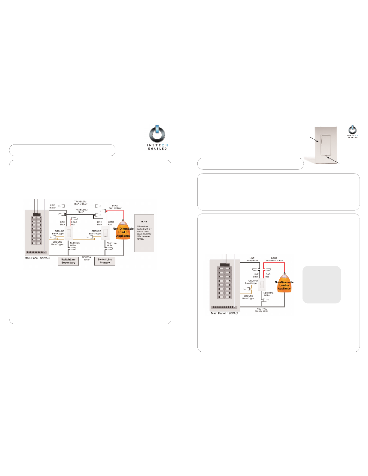
SWITCHLINC RELAY
SwitchLinc V2 Relay (#2476S)
Your new SwitchLinc Relay allows you to control lights and other non-dimmable
devices in your home at the touch of a button.
SET Button
PPrreeppaarraattiioonn
IInnssttaallllaattiioonn sshhoouulldd bbee ppeerrffoorrmmeedd oonnllyy bbyy aa qquuaalliiffiieedd eelleeccttrriicciiaann,, oorr bbyy aa hhoommeeoowwnneerr wwhhoo iiss ffaammiilliiaarr aanndd ccoommffoorrttaabbllee wwiitthh eelleeccttrriiccaall ccii