

INSTEON Smoke Bridge, 2982-222 Owner's Manual
Smoke Bridge
Owner’s Manual
2982-222
Page 1 of 14 2982-222 - Rev: 1/21/2014 8:34 AM

About Smoke Bridge ................................................................................................................................... 3
Features and Benefits ............................................................................................................................... 3
Installation ................................................................................................................................................... 3
First Alert Setup .......................................................................................................................................... 4
Pairing Smoke Bridge to First Alert Smoke Alarm .................................................................................... 4
INSTEON Setup ........................................................................................................................................... 4
INSTEON Controllers, Responders and Links .......................................................................................... 4
Configure INSTEON Settings .................................................................................................................... 4
Make Smoke Bridge a Controller .............................................................................................................. 5
Scenes ....................................................................................................................................................... 5
Make Smoke Bridge a Controller of Mult ip le Res po nder s ........................................................................ 6
Remove Smoke Bridge as a Controller ..................................................................................................... 6
Remove Smoke Bridge as a Controller of Multiple Responders ............................................................... 7
Local Control Operation and Testing ........................................................................................................ 8
Adjust Local Settings ................................................................................................................................. 9
INSTEON Blink on Traffic .......................................................................................................................... 9
Programming Lock .................................................................................................................................... 9
Resetting Smoke Bridge to its Factory Default Settings ........................................................................... 9
Specifications ............................................................................................................................................ 10
TROUBLESHOOTING ................................................................................................................................ 12
Certification and Warranty ....................................................................................................................... 14
Certification .............................................................................................................................................. 14
FCC and Industry Canada Compliance Statement ................................................................................. 14
ETL/UL Warning (Safety Warning) .......................................................................................................... 14
Limited Warranty ..................................................................................................................................... 14
Limitations................................................................................................................................................ 14
Page 2 of 14 2982-222 - Rev: 1/21/2014 8:34 AM
About Smoke Bridge
In the Box
Tools Needed
Optional Accessories
Smoke Bridge
None
Hub
Quick Start Guide
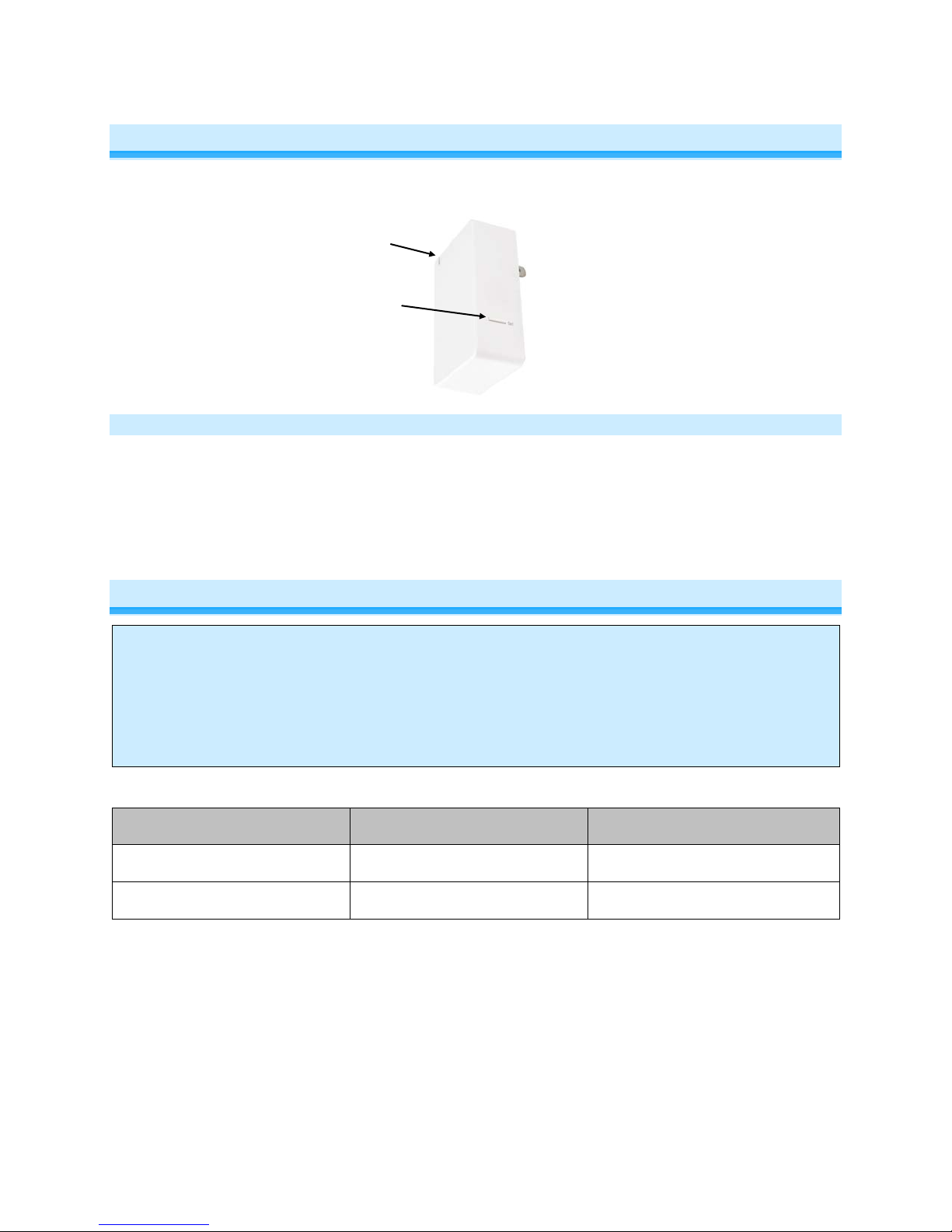
Set button
Status LED
Features and Benefits
- Bridges First Alert® ONELINK® Smoke and CO Alarms to the INSTEON network
- Can contain up to 400 controller/responder links
- All settings preserved in non-volatile memory, even through power failures
- Beeper for easy setup assistance
- Local programming lockout available via software
- 2-year warranty
Installation
CAUTION
Read and understand t hese instructions before installing and retain them for future reference.
Smoke Bridge is intended for installation in accordance with the National E lectric Code and l ocal regulations in the United
States or the Canadian Electrical Code and local regulations in Canada. Use indoors only. Smoke Bridge is not designed
nor approved for use on power lines other than 120V 60Hz, single phase. Attempt ing to use Smoke Br idge on nonapproved power lines may have hazardous consequences.
Note:
- The Smoke Bridge works with the First Alert® ONELINK® Smoke Alarm. This is a required
accessory.
- The Smoke Bridge does not have the ability to receive wireless RF signals from INSTEON devices.
Page 3 of 14 2982-222 - Rev: 1/21/2014 8:34 AM

First Alert Setup
Controller
Responder
Link
Pairing Smoke Bridge to First Alert Smoke Alarm
1) Press and hold Smoke Bridge set button until it beeps
Smoke Bridge LED will start blinking green
You will have four minutes to complete the next steps before linking mode times out
2) Press and hold First Alert Smoke Alarm test button until it beeps or says “testing”
First Alert Smoke Alarm will cycle through its test alert messages
Smoke Bridge LED will start blinking red, indicating traffic from the First Alert Smoke Alarm
Smoke Bridge LED will stop blinking when First Alert Smoke Alarm finishes sending message
3) Test pairing by pressing and holding Test button on First Alert Smoke Alarm
Smoke Bridge LED will blink red until the First Alert Smoke Alarm message is complete
INSTEON Setup
Some products have subtle differences in their setup procedures. Please refer to the other devices’
owner’s manuals for details.
INSTEON Controllers, Responders and Links
• The INSTEON “transmitter” is called a controller
• The INSTEON “receiver” is called a responder
• The association between the controller and responder is called a link
Note that a link is one way. If you wish to have control “the other way,” simply add a link “the other way.”
Configure INSTEON Settings
Most Smoke Bridge links and settings can be configured locally with the module’s Set button.
All Smoke Bridge settings can be managed remotely via software (sold separately).
Page 4 of 14 2982-222 - Rev: 1/21/2014 8:34 AM

Make Smoke Bridge a C ontr ol l er
1) Press and hold Smoke Bridge set button until it beeps
Smoke Bridge LED will start blinking green
You will have four minutes to complete the next steps before linking mode times out
2) Adjust responder to desired state
3) Press and hold responder set button until it double-beeps
Smoke Bridge will doubl e-beep and its LED will stop blinking
4) To test, first change the responder to a different state then the desired state
5) Test by tapping Smoke Bridge set button
The Set button will cycle through the following notifications with a brief delay between each
- Smoke detected
- Carbon Monoxide (CO) detected
- Low Battery detected
- Error
- All Clear
Smoke Bridge LED will blink red during these steps
~15 seconds after it sends the All Clear command, it will turn solid green
Responder will respond appropriately
1
2
Scenes
Devices in a scene can each have different settings. This provides for advanced scene creation. Software
is recommended for scene management.
Example of a scene with Smoke Bridge as a Controller:
1) Press and hold Smoke Bridge set button until it beeps
Smoke Bridge LED will start blinking green
2) Tap Smoke Bridge set button
Smoke Bridge LED will start double-blinking green
3) For each scene member:
a. Adjust member to desired scene state
b. Press and hold Set button until it double-beeps
4) Tap Smoke Bridge set button
Smoke Bridge will beep and LED will stop blinking
5) To test, first change the responder to a different state then the desired state
6) Test by tapping Smoke Bridge set button
The Set button will cycle through the following notifications with a brief delay between each
- Smoke detected
- Carbon Monoxide (CO) detected
- Low Battery detected
- Error
- All Clear
Smoke Bridge LED will blink red during these steps
1
If responder is a multi-scene device such as a KeypadLinc, tap scene button you wish to control until the LED is in the desired scene state (on or off).
2
If either controller or responder LED continues blinking, the addition failed. Tap device’s Set button until LED stops blinking and try linking again.
Page 5 of 14 2982-222 - Rev: 1/21/2014 8:34 AM
 Loading...