

INSTEON On/Off Outlet Owner's Manual

On/Off Outlet
On/Off Outlet
Owner’s Manual
Owner’s Manual

Contents
Getting Started
INSTEON Wall Outlet 4
On/O Outlet
Buttons
Tools Needed for Installation
Disconnect Power
Installation Timeline
Installation 6
Installation Diagrams
End-of-Run Outlet 10
Middle-of-Run Outlet 11
Switched Outlet 12
INSTEON Links
Understanding Linking 15
Adding to the INSTEON Hub 17
Software-Only Features
Beep on Button Press 19
Blink on Trac
Disable Local Programming
Error Blink
LED Brightness 20
Local Programming
Flow Chart 23
LED Brightness 24
RF Beacon
Load Sense 25
Soft Factory Reset 26
Factory Reset
Factory Reset 28
Appendix
Specications 30
Troubleshooting 33
Certications and Warnings 35
Product Warranty 36
Getting Started
Getting Started
Everything you need to quickly get up and running.
Everything you need to quickly get up and running.
3
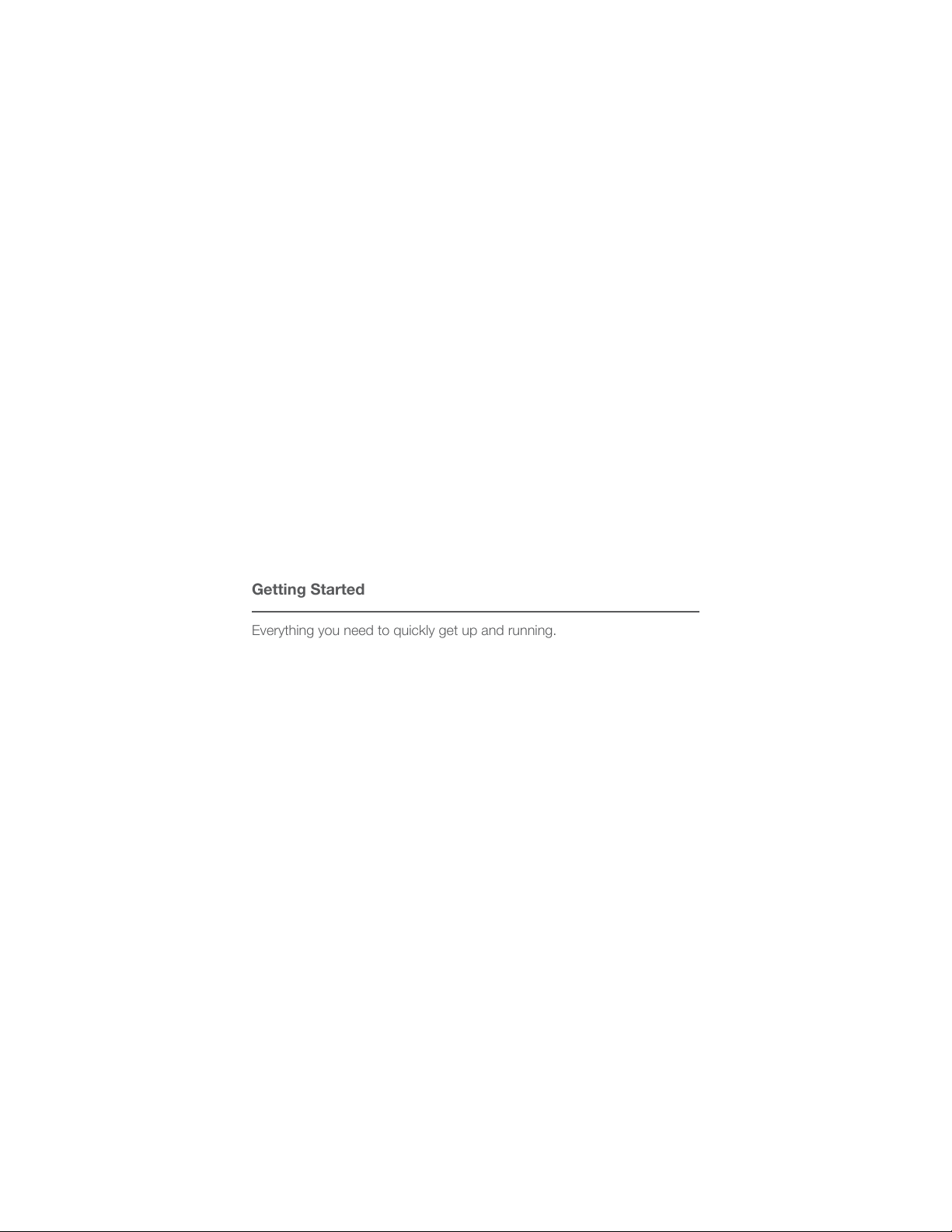
INSTEON Wall Outlet
Status LEDs
On
O
On/O &
Set Buttons
On/O Outlet
Upper
Outlet
Tamper
Resistant
Lower
Outlet
Tamper
Resistant
Upper
Lower
Buttons
Tap to turn the upper outlet on or o.
See sections on Basic Linking and
Local Programming for additional set
button functions.
Tap to turn the lower outlet on or o.
See sections on Basic Linking and
Local Programming for additional set
button functions.
Tools Needed for Installation Disconnect Power
Phillips Screwdriver
Flathead Screwdriver
Always disconnect power before
installation. Contact INSTEON
Voltage Detector
Support when uncertain about
installation.
1-866-243-8022
Wire Cutter / Stripper
4
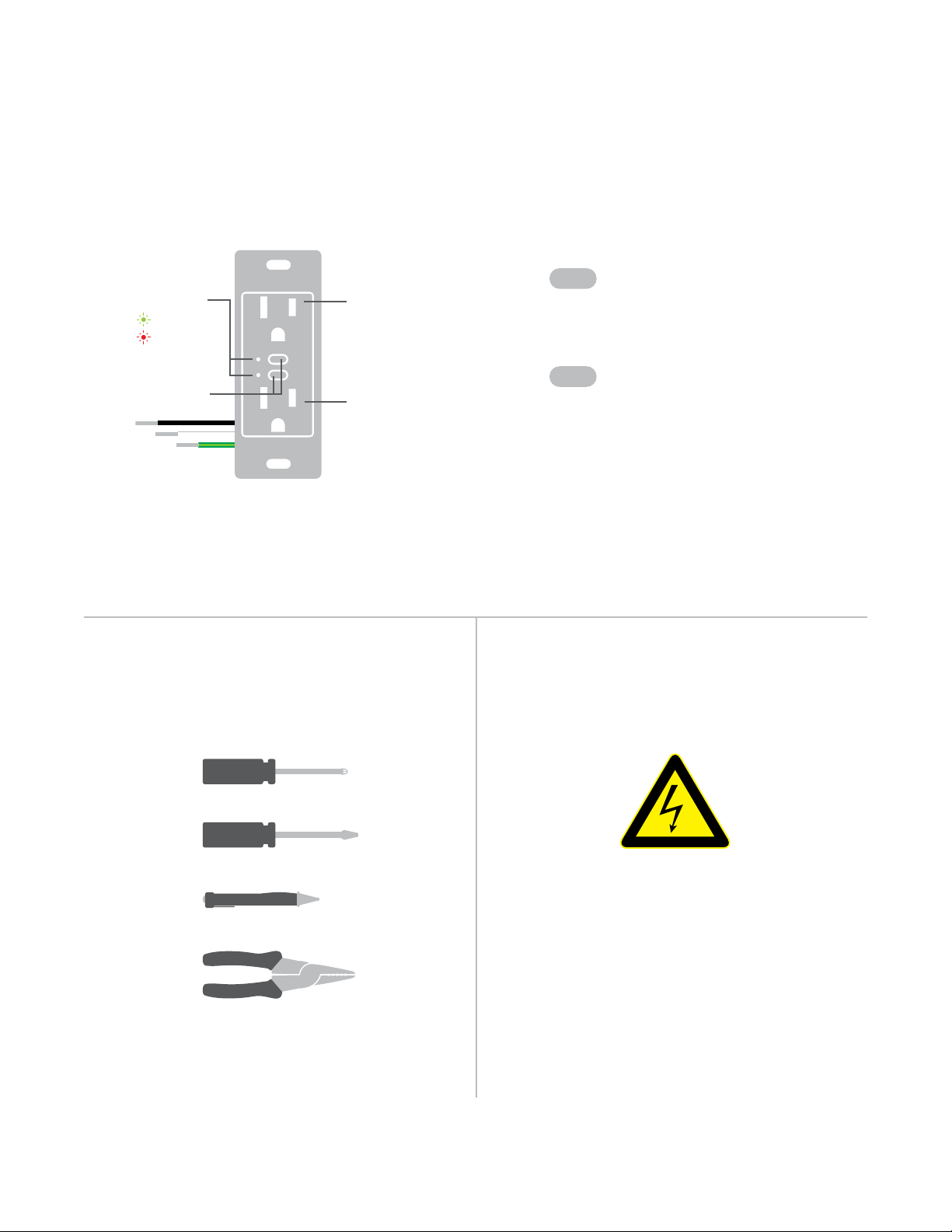
Installation Timeline
Installation Timeline
Disconnect Power
Disconnect Power
Reconnect Power
Reconnect Power
Disconnect Power
Disconnect Power
Unbox and read instructions
Unbox and read instructions
Remove the old outlet
Remove the old outlet
Identify Line wire
Identify Line wire
Reconnect Power
Reconnect Power
Connect the outlet wires to
Connect the outlet wires to
the junction box wires
the junction box wires
Carefully install the outlet into
Carefully install the outlet into
the junction box
the junction box
Test the outlet by tapping a
Test the outlet by tapping a
set button to turn on
set button to turn on
Install wall plate
Install wall plate
55
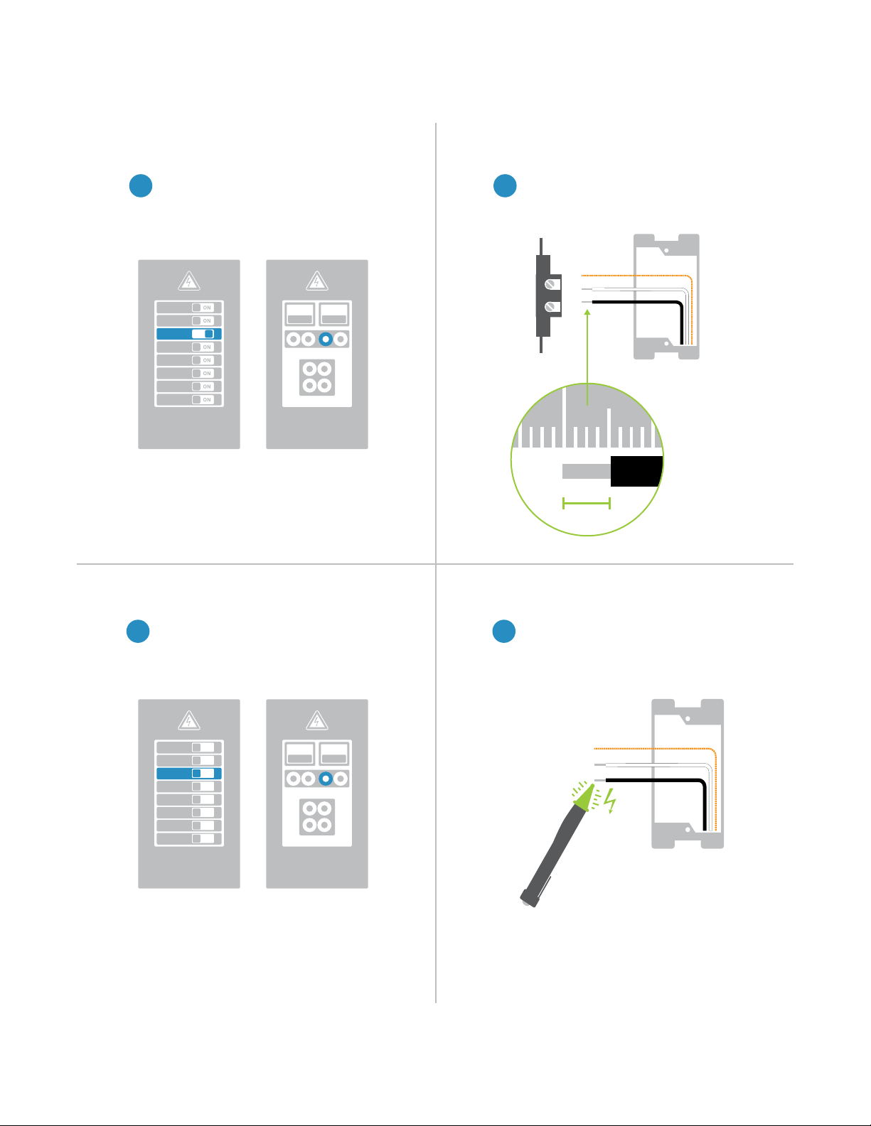
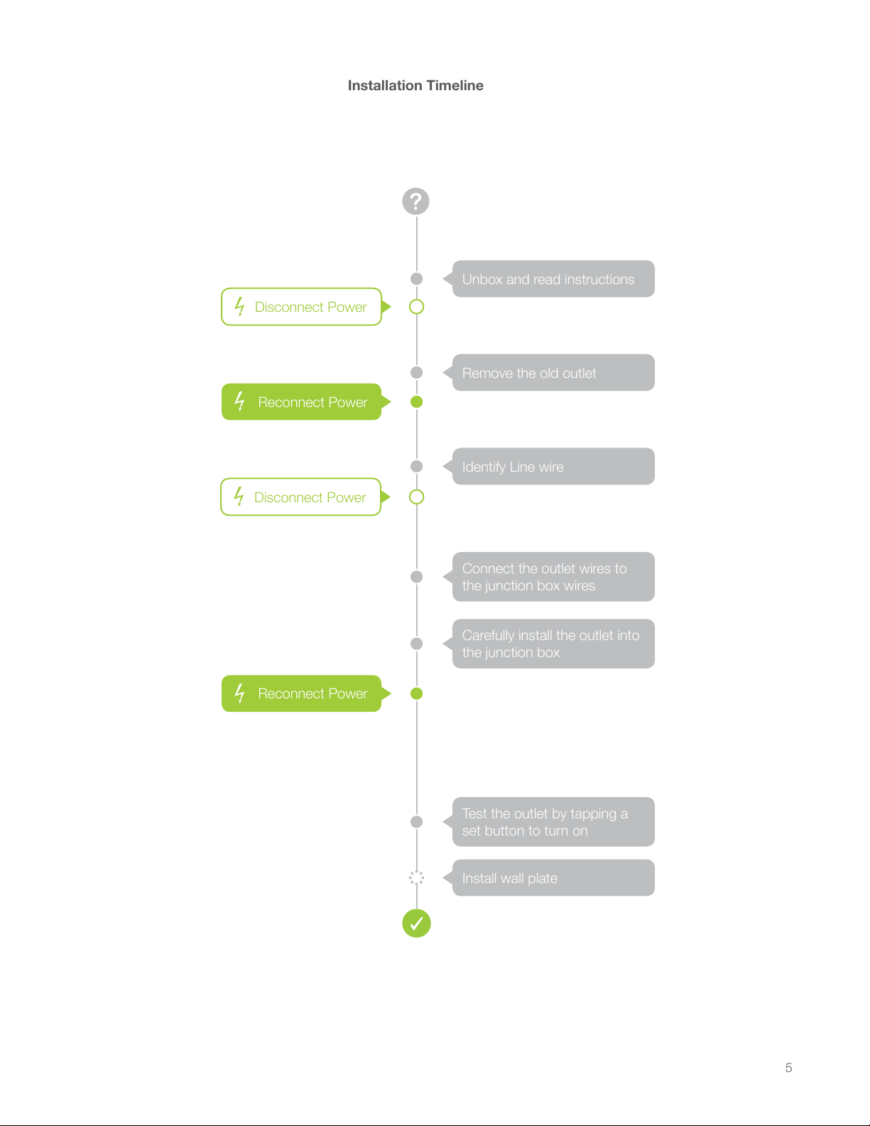
Installation
1 2
Disconnect Power Remove the Old Outlet
Turn o power to your outlet at the
1 2
electrical service panel.
ON ON
or
Remove the old outlet and disconnect
the wires.
Circuit Breakers
Fuse Panel
Turn on power at the circuit breaker.
ON
ON
ON
ON
ON
ON
ON
ON
or
ON ON
½”
12mm
Identify LineReconnect Power
Use a voltage detector to identify the
43
line wire. Line will be energized.
Circuit Breakers
Fuse Panel
6
Installation
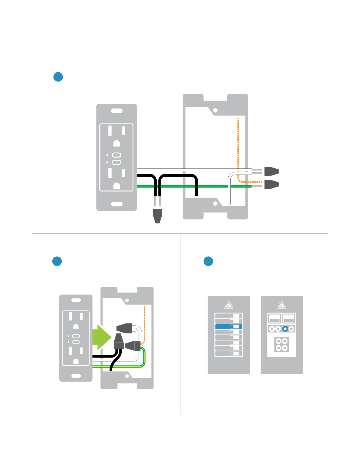
Wire-In the Outlet
Turn o power at the circuit breaker. Connect the Outlet wires to the identied wires in the junction box.
5
Verify that the wire nuts are secure and that no exposed copper wire is visible. Additional wiring diagrams
can be found in the Installation Diagrams section.
Neutral
Ground
Mount the Outlet into the junction box.
Line
Reconnect PowerInstall the Outlet
Turn power on to the outlet at the circuit
76
breaker panel.
ON
ON
ON
ON
ON
ON
ON
ON
or
Circuit Breakers Fuse Panel
ON ON
7
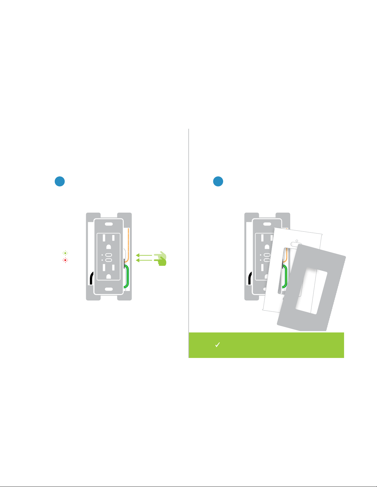
Test your Outlet by tapping one of the
set buttons to turn On and O.
Installation
Install Wall PlateTest the Outlet
Complete installation by reattaching
98
your wall plate. For the best look, us an
INSTEON Screwless Wall Plate.
On
O
Installation of your Wall Outlet is
now complete.
8
Installation Diagrams
Installation Diagrams
Use the installation diagrams in this section to help you wire
Use the installation diagrams in this section to help you wire
your Wall Outlet.
your Wall Outlet.
9
End-of-Run Outlet
Line
Neutral
Ground
10
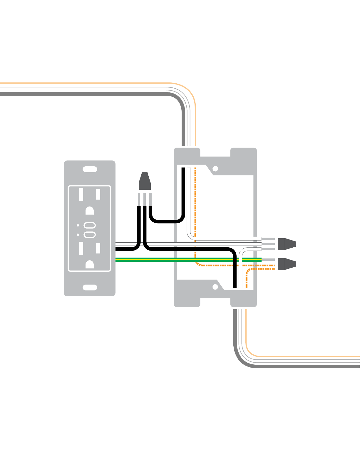
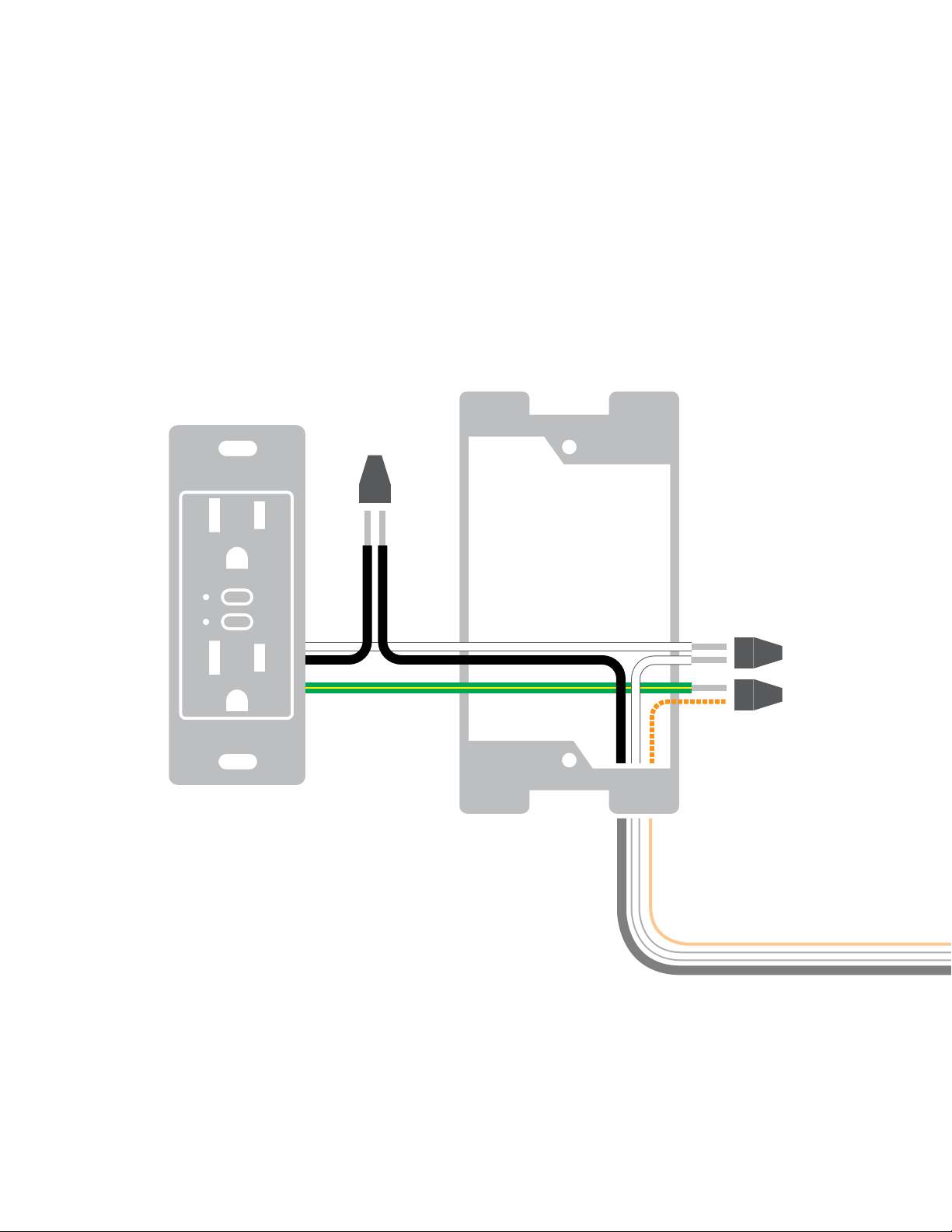
Middle-of-Run Outlet
Line
Neutral
Ground
11
 Loading...