

Page 1
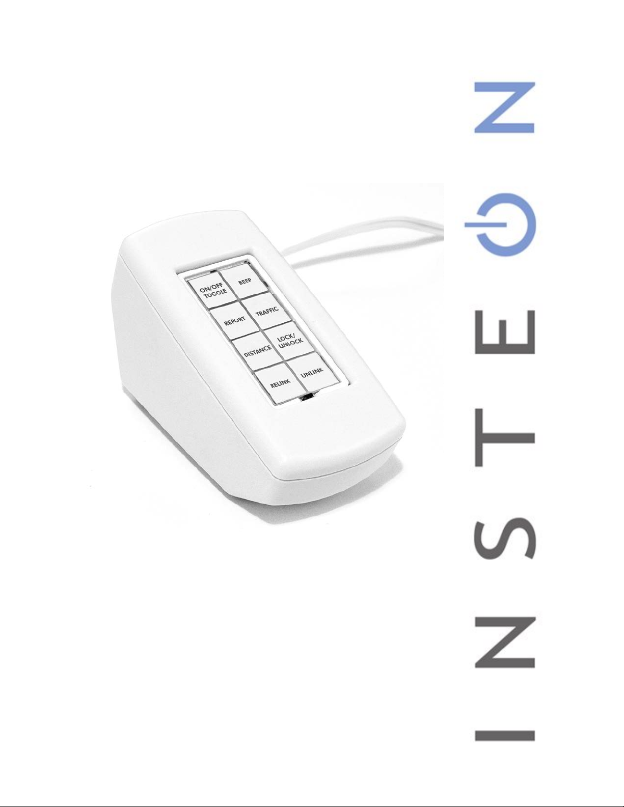
INSTEON Diagnostic Keypad
Owner’s Manual
2993-xx2
Page 1 of 10 2993-xx2 - Rev: 3/11/2014 9:21 AM 9:21:55 AM
Page 2

Features ......................................................................................................................................................................... 3
Installation ..................................................................................................................................................................... 3
Test Button Descriptions ............................................................................................................................................. 4
ON/OFF TOGGLE ....................................................................................................................................................... 4
BEEP ........................................................................................................................................................................... 4
REPORT* .................................................................................................................................................................... 4
TRAFFIC ...................................................................................................................................................................... 4
DISTANCE ................................................................................................................................................................... 4
LOCK/ UNLOCK* ......................................................................................................................................................... 4
RELINK* ...................................................................................................................................................................... 4
UNLINK* ...................................................................................................................................................................... 4
Directions ....................................................................................................................................................................... 4
ON/OFF TOGGLE – Control Test ............................................................................................................................... 5
BEEP – Signal Test ..................................................................................................................................................... 5
REPORT Mode ............................................................................................................................................................ 5
TRAFFIC – Corruption and Noise Monitor .................................................................................................................. 5
DISTANCE Mode ......................................................................................................................................................... 6
LOCK/UNLOCK ........................................................................................................................................................... 6
RELINK ........................................................................................................................................................................ 7
UNLINK ........................................................................................................................................................................ 7
Common Problem Solving Techniques ...................................................................................................................... 7
Testing RF-Only Devices for Access Point/Dual-Band Device Placement ................................................................. 7
Locating Noise Problems ............................................................................................................................................. 7
Determining Source of Signaling Problems ................................................................................................................. 8
Specifications ................................................................................................................................................................ 8
Certification and Warranty ......................................................................................................................................... 10
Certification ................................................................................................................................................................ 10
ETL/UL Warning (Safety Warning) ............................................................................................................................ 10
Limited Warranty ........................................................................................................................................................ 10
Limitations .................................................................................................................................................................. 10
Page 3
In the Box
Tools Needed
INSTEON Diagnostic Keypad
INSTEON controllers to be tested
Tabletop Enclosure
Manual
CAUTIONS AND WARNINGS
Read and understand these instructions before installing and retain them for future reference.
This product is intended for installation in accordance with the National Electric Code and local regulations in the United States or the Canadian
Electrical Code and local regulations in Canada. Use indoors only. This product is not designed or approved for use on power lines other than
120VAC- 60Hz, single phase. Attempting to use this product on non-approved power lines may have hazardous consequences. Use only
indoors.
Features
This INSTEON Diagnostic Keypad can be used to:
• Find and diagnose signaling issues
• Test the signaling quality of an installation
• “Stress” the house by running a distance test
• Intensively test signaling to a single device
• Remove guesswork for placement of Access Points specifically intended to communicate to RF-only devices
Installation
Before using the Diagnostic Keypad, follow the instructions that are included with the Keypad Tabletop Enclosure.
Page 3 of 10 2993-xx2 - Rev: 3/11/2014 9:21 AM 9:21:55 AM
Page 4

Test Button Descriptions
Diagnostic Keypad)**
ON/OFF
TOGGLE
Sends on/off broadcast
without confirmations to
unit under test
REPORT*
Monitors the quality of
control signals from the
device under test and
beeps upon receipt of
success reports
DISTANCE
Sends alternating fast-
ons and fast-offs to unit
under test, beeping
upon receipt
BEEP
Sends a beep message
to unit under test (some
responders will still
beep even after
unlinking from
TRAFFIC
Blink on valid traffic
and long-beep upon
collisions/noise
LOCK/
UNLOCK*
Disable local setup of
unit under test
Note: Unit under test = last responder linked
*This feature only works with INSTEON devices shipped after March 2012 (i2CS).
**Only applies to devices shipped prior to March 2012.
RELINK*
Relinks to last unit
under test
UNLINK*
Unlinks the unit under
test
Directions
Note:
- This manual presumes user has a moderate to expert understanding of INSTEON and INSTEON products.
- Diagnostic Keypad only contains a single link. When you are finished testing a device, be sure to UNLINK it from
Diagnostic Keypad before linking your nex t de vice. If you link a second device wit hout un link ing the firs t, it wil l
overwrite the existing link and the first device will still contain a half-link to Diagnostic Keypad. The first device
will have to be factory reset to remove the half-link.
- UNLINK device upon completion of test. Otherwise, the device under test will retain a responder link.
Page 4 of 10 2993-xx2 - Rev: 3/11/2014 9:21 AM 9:21:55 AM
Page 5

ON/OFF TOGGLE – Control Test
This button sends On and Off commands to unit under test.
1) Link Diagnostic Keypad as a controller of the unit under test.
2) Plug in Diagnostic Ke ypad at a test location.
3) Tap ON/OFF TOGGLE button.
Responder will turn on or off.
4) Move Diagnostic Ke ypad to other outlets if/as desired.
5) If unit testing is complete, UNLINK device.
BEEP – Signal Test
This button sends a beep command to unit under test. This allows you to test devices you don’t
wish to toggle on and off and/or from locations where you can hear the responder’s beep but
cannot see the unit under test.
1) Link Diagnostic Keypad as a controller of the unit under test.
2) Plug in Diagnostic Keypad at a test location.
3) Tap BEEP button.
Responder will beep (unless signal does not reach responder).
4) Move Diagnostic Ke ypad to other outlets if/as desired.
5) If unit testing is complete, UNLINK device.
REPORT Mode
ON/OFF
TOGGLE
REPORT TRAFFIC
DISTANCE
RELINK UNLINK
ON/OFF
TOGGLE
REPORT TRAFFIC
DISTANCE
RELINK UNLINK
BEEP
LOCK/
UNLOCK
BEEP
LOCK/
UNLOCK
This test allows you to monitor the quality of control signals from the device under test and is
commonly used to commission an installation. This mode does not require any links.
ON/OFF
TOGGLE
BEEP
1) Plug in Diagnostic Ke ypad at a test location.
2) Tap REPORT button until its LED is illuminated.
REPORT TRAFFIC
3) Activate scenes from as many devices as you wish.
Keypad will beep at beginning of scene message.
Keypad will double-beep upon receipt of success report with no errors.*
Keypad will long-beep upon receipt of success report with errors.*
DISTANCE
LOCK/
UNLOCK
*The success report feature was released in devices shipped after March 2012.
RELINK UNLINK
A small number of INSTEON devices do not support this feature.
The delay between the beep and double-be ep will vary depending on the number of responders in the scene.
o The delay for each responder is approximately 0.2 seconds (10 responders ~ 2 seconds).
o If the delay is longer, it may be an indication of difficulty in communications to one or more
responders.
TRAFFIC – Corruption and Noise Monitor
This test allows you to monitor in-band noise and INSTEON traffic on the powerline. This does not
require any links.
1) Plug in Diagnostic Ke ypad at a test location.
2) If button LED is not illuminated, tap the TRAFFIC button.
3) Observe TRAFFIC button LED for a few moments or minutes.
LED blinks indicate valid INSTEON mess ages .
Keypad will emit a long beep upon each corrupted message (commonly caused by
collisions/noise).
4) Initiate a scene from an INSTEON controller.
LED will blink during valid INSTEON traffic.
Excessive blinking is caused by message failures, commonly from a scene responder
Page 5 of 10 2993-xx2 - Rev: 3/11/2014 9:21 AM 9:21:55 AM
ON/OFF
TOGGLE
REPORT TRAFFIC
DISTANCE
RELINK UNLINK
BEEP
LOCK/
UNLOCK
Page 6

member that is no longer active.
5) Move Diagnostic Ke ypad to other outlets if/as desired.
If beeping is frequent, you may have a device generating noise. Move Diagnostic Keypad around until the beeping
occurs most frequently and you should be close to the source. Try turning off devices one at a time until noise
subsides, then install a FilterLinc to isolate network from noise source.
Another means of locating a noise source is to add the DISTANCE test (see below) to a TRAFFIC test. This is
especially helpful in locating noise sources in smaller and less busy installations.
DISTANCE Mode
1) Plug in Diagnostic Ke ypad at a test location.
2) Tap REPORT and TRAFFIC buttons until their LEDs are off.
ON/OFF
TOGGLE
BEEP
3) Tap DISTANCE button until its LED is off.
4) Link the Diagnostic Keypad as a controller of the unit under test.
5) If unit under test should not be turned on and off rapidly, tap UNLINK button.
REPORT TRAFFIC
6) Tap DISTANCE button unt il LED is on.
Keypad will send fast-on and fast-off commands as quickly as possible.
Unit beeps upon rec e ipt of acknowledged commands.
DISTANCE
LOCK/
UNLOCK
Faster beeping means better communication.
Four beeps/second indicate responder hearing message directly (0 hops).
RELINK UNLINK
Two beeps/second indicate responder 3 hops away.
7) Important: upon test completion, tap DISTANCE button until LED is off.
8) If testing the unit under test is complete, UNLINK device.
LOCK/UNLOCK
This button allows you to disable (or re-enable) local setup of unit under test. (This feature is in all products shipped
after March 2012.) LOCK/UNLOCK prevents accidental changes being made to on-level, ramp rates, etc. To
determine whether local setup is enabled on a device, press and hold its Set button for 5 seconds. If its LED starts
blinking, local setup is enabled; tap Set button until LED stops blinking.
1) Link Diagnostic Keypad as a controller of the unit under test (device to be locked or
unlocked).
Note: You cannot UNLINK a device from Diagnostic Keypad unless it was the last
device linked before programming lock was en abled. If another dev ice is still linked to
Diagnostic Keypad, remove the link by using home automation software (such as
HouseLinc) or performing a factory on the device.
2) Tap LOCK/UNLOCK button.
a. If LED is on, you have locked/disabled local setup.
b. If LED is off, you have unlocked/re-enabled local setup.
3) Tap again if device is not in the desired mode.
4) If unit testing is complete, UNLINK device.
Note: If you LOCK a unit under test and th en link Diagnostic Keypad to an other device, Diagnostic Key pad cannot
UNLOCK the first unit under test. You will need to use software (such as HouseLinc) to UNLO CK it or perform a
factory reset.
ON/OFF
TOGGLE
REPORT TRAFFIC
DISTANCE
RELINK UNLINK
BEEP
LOCK/
UNLOCK
Page 6 of 10 2993-xx2 - Rev: 3/11/2014 9:21 AM 9:21:55 AM
Page 7

RELINK
This is a convenient feature that quickly relinks a device under test when you hav e unlinked it and
disabled its local setup. It is also handy to re-link to a device at a different level/state.
1) Tap RELINK button to relink Diagnostic Keypad to unit under test.
UNLINK
Unlinking is important when testing is complete on any device.
1) Tap UNLINK button to remove link from unit under test.
ON/OFF
TOGGLE
REPORT TRAFFIC
DISTANCE
RELINK UNLINK
ON/OFF
TOGGLE
REPORT TRAFFIC
DISTANCE
RELINK UNLINK
BEEP
LOCK/
UNLOCK
BEEP
LOCK/
UNLOCK
Common Problem Solving Techniques
Testing RF-Only Devices for Access Point/Dual-Band Device Placement
• Place the RF-only device in the desired location.
• Plug Diagnostic Keypad into the desired outlet.
• Link Diagnostic Keypad as a controller of the RF-only device.
• Put the RF-only device into linking mode again.
o It will remain in that mode and be testable for approximately 4 minutes.
• Use DISTANCE mode to test communications to the RF-only device.
o If the communications are consistent, the Access Point/dual-band device is in a good location.
o If the communications are not consistent, relocate either the RF-only device or the Access
Point/dual-band device and retest.
If you relocate the Access Point/dual-band device, move Diagnostic Keypad with it.
Locating Noise Problems
• Enable TRAFFIC mode (disable REPORT and DISTANCE).
• Activate scenes from various locations (or activate DISTANCE mode to create traffic).
• If you hear more beeps, that means more noise in the INSTEON band.
o Beeping indicates bad CRC (a message in which the Cyclic Redundancy Check indicates that there
is at least one incorrect bit in the message).
• Move the tester to different outlets throughout the house to find the outlet with the closest proximity to the
noise source (Diagnostic Keypad will emit the fastest beeping).
• With the tester plugged in, try removing devices that might be a source of noise (e.g., power supplies,
laptops, chargers or video game consoles).
Page 7 of 10 2993-xx2 - Rev: 3/11/2014 9:21 AM 9:21:55 AM
Page 8

• When you have identified the noise source, install a FilterLinc to isolate the noise source from the INSTEON
General
Product name
INSTEON Diagnostic Keypad
Brand / manufacturer
INSTEON
US: 2993-222
UPC
813922012699
FCC ID
SBP23342
Industry Canada
5202A-23342
Warranty
2 years, limited
INSTEON
INSTEON powerline mesh repeater
Yes
INSTEON RF mesh repeater
N/A, powerline only
INSTEON controller
Yes
network.
Determining Source o f Signaling Problems
• A problem area would be an outlet in whic h the tester has difficulty talking to the unit under test.
• Enable DISTANCE mode.
• Search the following list for your situation:
o No beeping and no On/Off of the device under test.
Make sure device under test is linked as responder to Diagnostic Keypad.
There may not be a signal path between Diagnostic Keypad and device under test.
• Confirm phases are coupled.
• Add dual-band INSTEON products if necessary.
There may be noise at/near the de vice und er test.
• Find and filter the noise-making device with a FilterLinc.
o No beeping, but the device under test goes on and off.
The device under test is receiving the commands but the Diagnos tic Keypad is not receiving
the device’s positive acknowledgement that the command was received.
Look for noise at the Diagnostic Keypad’s location. Move Diagnostic Keypad if necessary.
o Beeping, but the device under test doesn’t go on or off.
Acknowledgement may be coming from a different unit. Link to intended device under test.
Try moving Diagnostic Keypad to a different location and using ON/OFF TOGGLE to turn the
device on and off.
Confirm that the device was not linked at off. Turn the device on using its local switch, then
press the ON/OFF TOGGLE button and verify if the device under test turns off but not on. If
linked to off, relink Diagnostic Keypad with device under test set to on.
o The beeping on/off cadence is slower than other out let s .
The path to the device under test is longer, but this may not be a problem.
If the beep cadence is consistent, it’s likely not a problem.
As you use the Diagnostic Keypad, you will be able to more easily recognize the beep
patterns.
o The on/off beeping is spott y at best.
The path to the device under test is poor.
Add additional dual-band INSTEON devices to couple the phases.
There may be noise in the path. Find and filter the noise-making device with a FilterLinc.
Specifications
Manufacturer product number
Page 8 of 10 2993-xx2 - Rev: 3/11/2014 9:21 AM 9:21:55 AM
EU: 2993-422
Page 9

INSTEON responder
N/A
Maximum links / scenes
1
LED
White when a particular test mode is active.
LED brightness
Constant
Local control
N/A, not a load controller
Commands supported as controller
On, Off, Beep
Commands supported as responder N/A, not a load controller
RF range
N/A, powerline only
Phase bridge detect beac o n
N/A, powerline only
X10 – not supported
Mechanical
Mounting
Wires
Screw clamp connections
N/A
Case color
White
Set button
1
Plastic
UV stabilized polycarbonate
Beeper
Yes
Beep on button press
N/A
LED
White
Operating environment
Indoors
Operating humidity range
0-85% relative humidity
Electrical
2993-222: 110VAC (+/- 10%)
Frequency
50/60Hz
Load type(s)
N/A, not a load controller
Minimum load
N/A, not a load controller
User replaceable fuse
N/A
Hardwired remote control
N/A
Retains all settings without power
Yes, saved in non-volatil e EE P RO M
Standby power consumption
< 1 watt
FCC ID
N/A, powerline only
Safety approval(s)
ETL (Intertek Testing Services)
Tabletop enclosure
Standard lamp cord
Operating temperature range
32 o to 104 o F
Voltage
2993-422: 240VAC (+/- 10%)
Maximum load N/A, not a load controller
Page 9 of 10 2993-xx2 - Rev: 3/11/2014 9:21 AM 9:21:55 AM
Page 10

Certification and Warranty
Certification
This product has b een th orou ghly tes te d by ITS ETL SE MK O, a nati onal ly rec ogni zed ind epend ent third-pa rt y testi ng labo rator y. The N ort h Americ an ET L L isted m ark
signifies that th e device has been te sted to and has me t the requi rements of a widely reco gnized con sensus of U .S. and C anadian dev ice saf ety standar ds, that th e
manufacturing site has been audited, and that the manufacturer has agreed to a program of quarterly factory follow-up inspections to verify continued conformance.
ETL/UL Warning (Safety Warning)
CAUTION: To reduce the ri sk of o verh eati ng and p ossi ble dam age to ot her e quipme nt, d o not inst all thi s devic e to c ontrol a r ece ptacle, a motor-operat ed appl iance , a
fluorescent lighting fixture, or a transformer-suppli ed ap pl ia nce.
Gradateurs comm andant une lam pe a fil ament de tungsten e – afin de reduir e le ris qué de s urchauf fe et la possibil ite d’ endomm agement a d’autres mate riels, n e pas
installer pour commander une prise, un appareil a moteur, une lampe fluorescente ou un appareil alimente par un transformateur.
Limited Warranty
Seller warrants to the ori ginal consumer purch aser of this product that, f or a period of two years from the date of purchase, this p roduct will be free from defects in
material and work m anship and will perform in substantial conf orm ity to the descripti on of t h e p ro duct in this Owner’s Man ual. This warranty sh all no t ap ply to defects or
errors caused by misuse or neglect. If the prod uc t is f ou nd t o be d efective in material or workmanship, or if the produ ct does not perform as warranted above duri ng th e
warranty period, Sel ler will ei ther r epair it, replac e it, or refu nd th e purcha se price, at its opti on, upo n receipt of the pr oduc t at the add ress bel ow, post ag e prepai d, with
proof of the date of pur chase a nd a n explan ation of t he defect o r error. T he repai r, repla cement, o r refund th at is pr ovided fo r above shal l be the f ull ext ent of Seller’s
liability with resp ect to this product. Fo r rep ai r or r epl ac em e nt d uring the warrant y period, call INSTEON a t 80 0-762-7845 with the Mo del # an d Rev i si on # of the device
to receive an RMA# and send the product, along with all other required materials to:
INSTEON
ATTN: Receiving
16542 Millikan Ave.
Irvine, CA 92606-5027
Limitations
The above warranty is in l ie u of and Seller disclaim s all othe r wa rra ntie s, whet her o ral o r writt en, e xpress or implied, incl udi ng a n y warr ant y o r m erc han ta bi li t y or fitn ess
for a particular pu rpose . An y implie d warr ant y, incl uding any w arran ty of m erchan tabili t y or fitness for a partic ula r purpos e, which may not be disc laimed or sup planted
as provided above shall be limi ted to the two-year of the express warr anty abov e. No other r epresent ation or cl aim of an y nature by an y person sh all be bin ding upo n
Seller or modify the terms of the above warranty and disclaimer.
Home automatio n devices have t he risk of failure to operate, in correct operati on, or electrical or mechanical tam pering. For optim al use, manu ally verify the device
state. Any home automation device should be viewed as a convenience, but not as a sole method for controlling your home.
In no event shall Seller b e liable for special, i ncidental, consequ ential, or other dam ages resulting from possession or use of thi s device, includin g without limitation
damage to property and, to the extent permitt ed b y la w, perso nal injur y, ev en if S ell er kne w or s houl d hav e kno wn o f the p ossi bilit y of suc h d amag es. S ome st ates d o
not allow limitati o ns on ho w lon g an implied wa rra nt y las ts a nd/or the exclusio n o r li m itation of damages, in which case the ab ove l im itations and/or e xcl usi o ns m a y not
apply to you. You may also have other legal rights that may vary from state to state.
U.S Patent No. 7,345,998, International patents pending (see www.inste on. c o m ).
© Copyright 2014 INSTEON, 16542 Millikan Ave., Irvine, CA 92606, 800-762-7845, www.insteon.com
Page 10 of 10 2993-xx2 - Rev: 3/11/2014 9:21 AM 9:21:55 AM
 Loading...