

Page 1
Smoke Bridge
Owner’s Manual
2982-222
Page 1 of 14 2982-222 - Rev: 1/21/2014 8:34 AM
Page 2

About Smoke Bridge ................................................................................................................................... 3
Features and Benefits ............................................................................................................................... 3
Installation ................................................................................................................................................... 3
First Alert Setup .......................................................................................................................................... 4
Pairing Smoke Bridge to First Alert Smoke Alarm .................................................................................... 4
INSTEON Setup ........................................................................................................................................... 4
INSTEON Controllers, Responders and Links .......................................................................................... 4
Configure INSTEON Settings .................................................................................................................... 4
Make Smoke Bridge a Controller .............................................................................................................. 5
Scenes ....................................................................................................................................................... 5
Make Smoke Bridge a Controller of Mult ip le Res po nder s ........................................................................ 6
Remove Smoke Bridge as a Controller ..................................................................................................... 6
Remove Smoke Bridge as a Controller of Multiple Responders ............................................................... 7
Local Control Operation and Testing ........................................................................................................ 8
Adjust Local Settings ................................................................................................................................. 9
INSTEON Blink on Traffic .......................................................................................................................... 9
Programming Lock .................................................................................................................................... 9
Resetting Smoke Bridge to its Factory Default Settings ........................................................................... 9
Specifications ............................................................................................................................................ 10
TROUBLESHOOTING ................................................................................................................................ 12
Certification and Warranty ....................................................................................................................... 14
Certification .............................................................................................................................................. 14
FCC and Industry Canada Compliance Statement ................................................................................. 14
ETL/UL Warning (Safety Warning) .......................................................................................................... 14
Limited Warranty ..................................................................................................................................... 14
Limitations................................................................................................................................................ 14
Page 2 of 14 2982-222 - Rev: 1/21/2014 8:34 AM
Page 3
About Smoke Bridge
In the Box
Tools Needed
Optional Accessories
Smoke Bridge
None
Hub
Quick Start Guide
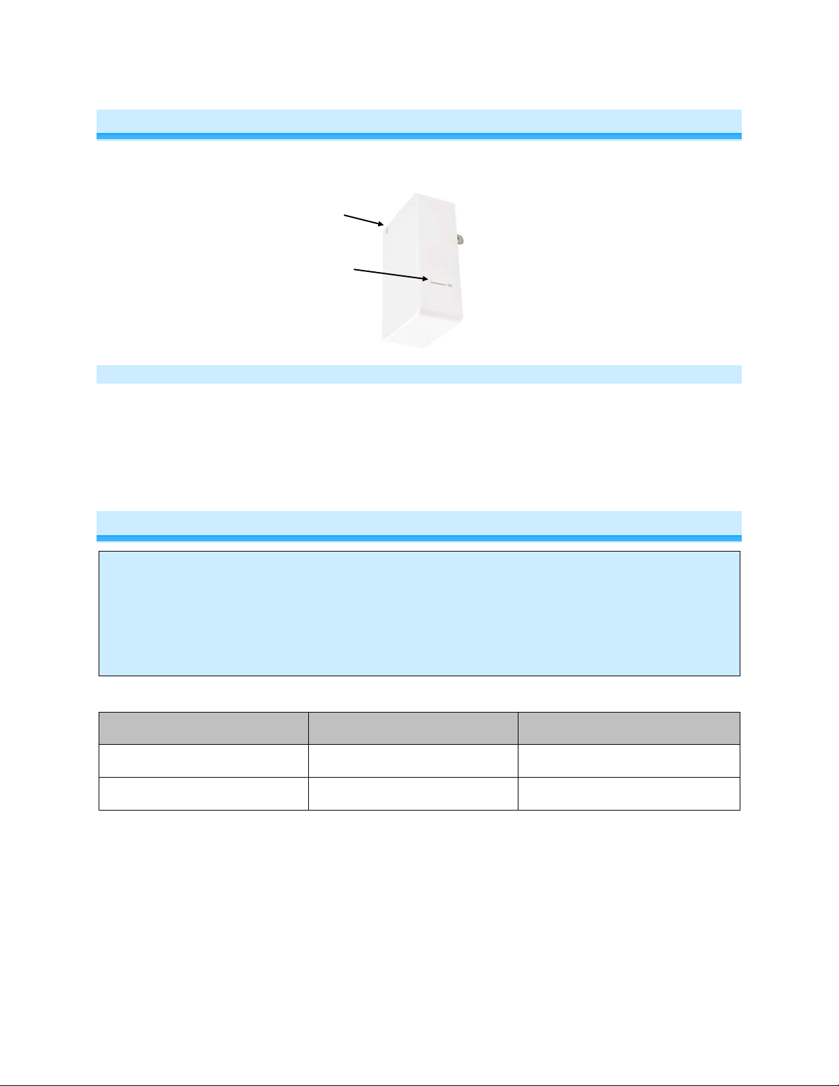
Set button
Status LED
Features and Benefits
- Bridges First Alert® ONELINK® Smoke and CO Alarms to the INSTEON network
- Can contain up to 400 controller/responder links
- All settings preserved in non-volatile memory, even through power failures
- Beeper for easy setup assistance
- Local programming lockout available via software
- 2-year warranty
Installation
CAUTION
Read and understand t hese instructions before installing and retain them for future reference.
Smoke Bridge is intended for installation in accordance with the National E lectric Code and l ocal regulations in the United
States or the Canadian Electrical Code and local regulations in Canada. Use indoors only. Smoke Bridge is not designed
nor approved for use on power lines other than 120V 60Hz, single phase. Attempt ing to use Smoke Br idge on nonapproved power lines may have hazardous consequences.
Note:
- The Smoke Bridge works with the First Alert® ONELINK® Smoke Alarm. This is a required
accessory.
- The Smoke Bridge does not have the ability to receive wireless RF signals from INSTEON devices.
Page 3 of 14 2982-222 - Rev: 1/21/2014 8:34 AM
Page 4

First Alert Setup
Controller
Responder
Link
Pairing Smoke Bridge to First Alert Smoke Alarm
1) Press and hold Smoke Bridge set button until it beeps
Smoke Bridge LED will start blinking green
You will have four minutes to complete the next steps before linking mode times out
2) Press and hold First Alert Smoke Alarm test button until it beeps or says “testing”
First Alert Smoke Alarm will cycle through its test alert messages
Smoke Bridge LED will start blinking red, indicating traffic from the First Alert Smoke Alarm
Smoke Bridge LED will stop blinking when First Alert Smoke Alarm finishes sending message
3) Test pairing by pressing and holding Test button on First Alert Smoke Alarm
Smoke Bridge LED will blink red until the First Alert Smoke Alarm message is complete
INSTEON Setup
Some products have subtle differences in their setup procedures. Please refer to the other devices’
owner’s manuals for details.
INSTEON Controllers, Responders and Links
• The INSTEON “transmitter” is called a controller
• The INSTEON “receiver” is called a responder
• The association between the controller and responder is called a link
Note that a link is one way. If you wish to have control “the other way,” simply add a link “the other way.”
Configure INSTEON Settings
Most Smoke Bridge links and settings can be configured locally with the module’s Set button.
All Smoke Bridge settings can be managed remotely via software (sold separately).
Page 4 of 14 2982-222 - Rev: 1/21/2014 8:34 AM
Page 5

Make Smoke Bridge a C ontr ol l er
1) Press and hold Smoke Bridge set button until it beeps
Smoke Bridge LED will start blinking green
You will have four minutes to complete the next steps before linking mode times out
2) Adjust responder to desired state
3) Press and hold responder set button until it double-beeps
Smoke Bridge will doubl e-beep and its LED will stop blinking
4) To test, first change the responder to a different state then the desired state
5) Test by tapping Smoke Bridge set button
The Set button will cycle through the following notifications with a brief delay between each
- Smoke detected
- Carbon Monoxide (CO) detected
- Low Battery detected
- Error
- All Clear
Smoke Bridge LED will blink red during these steps
~15 seconds after it sends the All Clear command, it will turn solid green
Responder will respond appropriately
1
2
Scenes
Devices in a scene can each have different settings. This provides for advanced scene creation. Software
is recommended for scene management.
Example of a scene with Smoke Bridge as a Controller:
1) Press and hold Smoke Bridge set button until it beeps
Smoke Bridge LED will start blinking green
2) Tap Smoke Bridge set button
Smoke Bridge LED will start double-blinking green
3) For each scene member:
a. Adjust member to desired scene state
b. Press and hold Set button until it double-beeps
4) Tap Smoke Bridge set button
Smoke Bridge will beep and LED will stop blinking
5) To test, first change the responder to a different state then the desired state
6) Test by tapping Smoke Bridge set button
The Set button will cycle through the following notifications with a brief delay between each
- Smoke detected
- Carbon Monoxide (CO) detected
- Low Battery detected
- Error
- All Clear
Smoke Bridge LED will blink red during these steps
1
If responder is a multi-scene device such as a KeypadLinc, tap scene button you wish to control until the LED is in the desired scene state (on or off).
2
If either controller or responder LED continues blinking, the addition failed. Tap device’s Set button until LED stops blinking and try linking again.
Page 5 of 14 2982-222 - Rev: 1/21/2014 8:34 AM
Page 6

~15 seconds after it sends the All Clear command, it will turn solid green
Responder will respond appropriately
Make Smoke Bridge a Controller of Multiple Responders
1) Press and hold Smoke Bridge set button until it beeps
LED will start blinking green
2) Tap Smoke Bridge set button
LED will start double-blinking green
3) For each responder you are adding:
- Adjust responder to desired scene state
- Press and hold Set button until it double-beeps
4) Tap Smoke Bridge set button
Smoke Bridge will beep and LED will stop blinking
5) To test, first change the responder to a different state then the desired state
6) Test by tapping Smoke Bridge set button
The Set button will cycle through the following notifications with a brief delay between each
- Smoke detected
- Carbon Monoxide (CO) detected
- Low Battery detected
- Error
- All Clear
Smoke Bridge LED will blink red during these steps
~15 seconds after it sends the All Clear command, it will turn solid green
Responder will respond appropriately
Remove Smoke Bridge as a Controller
If you no longer want Smoke Bridge to control another device (or are removing Smoke Bridge from your
network) it is important that you follow the instructions below for each responder.
1) Press and hold Smoke Bridge set button until it beeps
LED will start blinking gree n
2) Press and hold Smoke Bridge set button until it beeps aga in
LED will start blinking red
3) Press and hold responder set button until it double-beeps
Smoke Bridge will double-beep and LED will stop blinking
4) To test, first change the responder to a different state then the desired state
5) Test by tapping Smoke Bridge set button
The Set button will cycle through the following notifications with a brief delay between each
- Smoke detected
- Carbon Monoxide (CO) detected
- Low Battery detected
- Error
- All Clear
Smoke Bridge LED will blink red during these steps
~15 seconds after it sends the All Clear command, it will turn solid green
Responder will not respond
Page 6 of 14 2982-222 - Rev: 1/21/2014 8:34 AM
Page 7

Remove Smoke Bridge as a Controller of Multiple Responders
1) Press and hold Smoke Bridge set button until it beeps
LED will start blinking green
2) Press and hold Smoke Bridge set button until it beeps again
LED will start blinking red
3) Tap Smoke Bridge set button
LED will start double-blinking red
4) For each responder you are removing:
a. Press and hold Set button until it double-beeps
5) Tap Smoke Bridge set button
Smoke Bridge will beep and LED will stop blinking
6) To test, first change the responder to a different state then the desired state
7) Test by tapping Smoke Bridge set button
The Set button will cycle through the following notifications with a brief delay between each
- Smoke detected
- Carbon Monoxide (CO) detected
- Low Battery detected
- Error
- All Clear
Smoke Bridge LED will blink red during these steps
~15 seconds after it sends the All Clear command, it will turn solid green
Responder will not respond
Page 7 of 14 2982-222 - Rev: 1/21/2014 8:34 AM
Page 8

Tap Set Button Once Cycles
Responders
LED
Smoke detected
Responders for each group will
Blinking Red until ~10
Local Control Operati on and Test ing
through following:
Carbon Monoxide (CO) Detected
be activated as it cycles
through the various notifications
seconds after All Clear, then
Solid Green
Low Battery Detected
Error
All Clear
Notes:
If you link to other INSTEON devices using the Set button, only the “Smoke Detected” signal will trigger
the INSTEON devices. To verify Smoke Bridge puts the responders in the correct state, you must put the
responders into a different state and then use Set button to test.
If you are using software, such as HouseLinc to manage Smoke Bridge, you can create scenes for any of
the above groups.
The Smoke Detector Test group is only initiated by pressing and holding the Test button on the First Alert
smoke alarm.
Page 8 of 14 2982-222 - Rev: 1/21/2014 8:34 AM
Page 9

Adjust Local Settings
INSTEON Blink on Traffic
Default = disabled
This setting is only adjustable via software or a central controller. Smoke Bridge LED will blink green if it
detects noise that could disrupt communication. It will blink red when it sees traffic to it from its paired
First Alert Smoke Alarm.
Programming Lock
Default = disabled
This setting is only adjustable via software or a central controller. When enabled, Programming Lock will
disable the Set button so that a user can not adjust settings or modify links. This is typically used in
commercial or installer applications.
Resetting Smoke Bridge to its Factory Default Settings
All settings and scenes will be erased, including the link between the First Alert Smoke Alarm and the
Smoke Bridge. To continue to use the Smoke Bridge with a First Alert Smoke Alarm, you must relink
them using the steps in “Pairing Smoke Bridge to First Alert Smoke Alarm” above.
1) Unplug Smoke Bridge to remove power
2) Wait 5 seconds
3) Press and hold Set button while plugging in Smoke Bridge. Do not let go.
Smoke bridge will emit a long beep
4) When long beep stops, release Set button
A few seconds will pass
Smoke Bridge will double-beep
5) Relink Smoke Bridge and First Alert Smoke Alarm
Page 9 of 14 2982-222 - Rev: 1/21/2014 8:34 AM
Page 10

Specifications
General
Product name
INSTEON Smoke Bridge
Brand / manufacturer
INSTEON
Regions
North America
Manufacturer product number
2982-222
813922013450
Warranty
2 years
INSTEON
INSTEON controller
Yes
INSTEON responder
No
Bridging compatibility
First Alert® ONELINK® Responder
Maximum links
400
Smoke Sensed
Carbon Monoxide Sensed
Low Battery
Sensor Malfunction
All Clear
Blinks red when receiving data from First Alert OneLink
Setup LED brightness
Adjustable, from off to bright
Local control
None
Software Configurable
Yes
Up to 50 meters (150 feet) open air*
INSTEON Device Subcategory
0x0A
Mechanical
Plug in to polarized Type A socket
Enclosure color
INSTEON White
Specifications
UPC
Control groups/commands
Setup LED
Blinks green when INSTEON signals are detected
Commands Supported as responder Beep, status
First Alert ONELINK to Smoke
Bridge RF Range
INSTEON Device Category
*Range may vary due to local interference/building construction
0x10
Mounting
Page 10 of 14 2982-222 - Rev: 1/21/2014 8:34 AM
Page 11

Set button
1 on right side of case
Control buttons
None
Enclosure
ABS, UV stabilized, gloss finish
ID same as 2457 except blank out replaces receptacle and
Beeper
Yes
Beep on button press
Yes
Dimensions
3.2" H x 2.05" W x 1.05" D
Weight
2.4oz (.15lbs.), 68g
Operating environment
Indoors
Operating temperature range
32°F to 104°F (0°C to 40°C)
Operating humidity range
0-85 % relative
Storage temperature range
INSTEON ID labe l loc ation
On backside below unit label
Electrical
Ratings
120VAC ± 10%, 60Hz
Standby Power Consumpti on
0.8 Watts
Retains settings without power
Yes, saved in non-volatil e EE P RO M
Conforms to ANSI/UL Std. 508-2008
FCC ID: SBP2457D2A
up/down arrows are removed
-4 o to 158 o F (-20 o to 70 o C)
Safety approval(s)
Certified to CAN/CSA Std. C22.2#14-2008
FCC ID
IC: #5202A-2457D2A
All product specifications are subject to change.
Page 11 of 14 2982-222 - Rev: 1/21/2014 8:34 AM
Page 12

Problem
Possible Cause
Solution
The Status LED on
The Responder might
The responder and Smok e
Add additional INSTEON devices or move around
Large appliances, such as
Unlink any unused responders from Smoke Bridge.
If the above doesn’t work, perform a factory reset
TROUBLESHOOTING
Smoke Bridge is not
turning on.
Smoke Bridge won’t
Link or work with a
responder.
Smoke Bridge may not be
getting power.
have been reset without
Unlinking Smoke Bridge
from it.
Bridge may be on
opposite power line
phases.
The INSTEON signal may
be too weak.
refrigerators or air
conditioners, m a y be
producing electrical noise
on the power line.
Make sure Smoke Bridge is not plugged into a
switched outlet that is turned off.
Re-Link Smoke Bridge to the Responder.
Make sure two dual-band INSTEON devices are
properly installed to bridge the two power line
phases.
existing INSTEON devices. All INSTEON devices
act as INSTEON network repeaters.
Other electrical devices,
such as computers,
televisions, or power
strips, may be absorbing
the INSTEON signal.
Smoke Bridge m a y be
sending commands to a
Responders are taking
a long time to respond
to Smoke Bridge.
responder that is no
longer in use. Commands
for the unused responder
are being resent and
loading down the signal.
Page 12 of 14 2982-222 - Rev: 1/21/2014 8:34 AM
Install a power line noise filter (#1626-10) to filter
electrical noise and minimize signal attenuation.
HINT: If you are using home automation software,
you can easily check scene membership and
eliminate unnecessary Links.
on Smoke Bridge. See Resetting Smoke Bridge to
its Factory Default Settings.
Page 13

Problem
Possible Cause
Solution
Smoke Bridge can
Re-Link the responder to smoke bridge, while the
When I press Test on
Using the Set button to
Unplug Smoke Bridge for 10 seconds and then
If the above doesn’t work, perform a factory reset.
turn off a Responder,
rather than on.
The responder may be
linked at its off state.
responder’s load is on. See the Responder’s
Owner’s Manual for more detailed linking
instructions.
smoke alarm, the
Smoke Bridge
responders are not
turning on.
Smoke Bridge is
locked up.
create a link to a
responder links it to the
Smoke Detected group
only.
A surge or excessive
noise on the power line
may have glitched it.
To link to the test button group, you must use
software or a smart device (iOS or Android) app.
reinstall.
See Resetting Smoke Bridge to its Factory Default
Settings.
If you have tried these solutions, reviewed th is Owner’s Manual, and sti ll cannot res olve an issue you are
having with Smoke Bridge, please call:
INSTEON Support Line
866-243-8022
Page 13 of 14 2982-222 - Rev: 1/21/2014 8:34 AM
Page 14

Certification and Warranty
Certification
This product h as been t horoug hly test ed by ITS ETL S EMKO, a nati onally r ecogni zed inde pendent third-part y testi ng labo ratory. T he No rth Ameri can
ETL Listed mark signifies that the device has been tes ted to an d has met the requi rements o f a widel y recogni zed conse nsus of U.S. and Canadian
device safety sta ndards, t hat th e manu facturing s ite has b een audi ted, an d that th e manuf acture r has agr eed to a program of quarterly factor y followup inspections to verify will continued conformance.
FCC and Industry Canada Compliance Statement
This device complies with FCC Rules Part 15 and Industry Canada RSS-210 (Rev. 7). Operation is subject to the following two conditions:
(1) This device may not cause harmful interference, and
(2) This device must accept any interference, including interference that may cause undesired operation of the device.
Le present appareil est conforme aux CN R d’Industrie Canad a ap pli ca bles a u x appa rei ls r adio exempts de lic en ce. L’e xpl oitation est autoris e aux deux
conditions suivantes :
(1) l’appareil ne doit pas pro duir e de br oui ll a ge, et
(2) l’utilisateur de l’appareil doit accepter tout brouillage radiolectrique subi, mme si le brouillage est susceptible d’en compromettre le
fonctionnement.
The digital circuitry of this device has been tested and found to comply with the limits for a Class B digital device, pursuant to Part 15 of the FCC Rules.
These limits are designed to pro vide reasonable protection agai nst harmful inte rference in resid ential installatio ns. This equipm ent generates , uses,
and can radiate radio freque ncy energ y and, if not installe d and used in acco rdance with the instruct ions, may cau se harmful interference to radio and
television reception. However, there is no guarantee that interference will not occur in a particular installation. If this device does cause such
interference, whic h ca n be ve ri fie d by turning the device off a nd o n, th e us e r is enc o ur age d to el im i na te th e i nte rfe re nce b y o ne o r m ore of th e fol lo wi ng
measures:
- Re-orient or relocate the receiving antenna of the device experiencing the interference
- Increase the distance between this device and the receiver
- Co nnect the device to an AC outlet on a circuit different from the one that supplies power to the receiver
- Consult the dealer or an experienced radio/TV technician
WARNING: Chang es or m odificati ons t o this device not expr essly ap proved by th e part y responsi ble for compli ance c ould voi d the us er’s auth ority t o
operate the equipment.
ETL/UL Warning (Safety Warning)
CAUTION: To reduc e the risk of overheating and possible damag e to other equipment, d o not install this devic e to control a receptac le, a motor-
operated appliance, a fluorescent lighting fixture, or a transformer-supplied ap pli anc e.
Gradateurs comman dant une lampe a filam ent de tungstene – afin de r eduire le risqué de surc hauffe et la possibil ite d’endommagem ent a d’autres
materiels, ne pas installer pour commander une prise, un appareil a moteur, une lampe fluorescente ou un appareil alimente par un transformateur.
Limited Warranty
Seller warrants to the origin al consumer pur chaser of thi s product th at, for a peri od of two ye ars from the date of purcha se, this product will be free
from defects in mate rial and workmanship a nd will perform in substan tial conformity to the descri ption of the product in t his Owner’s Manual. This
warranty shall not appl y to defec ts or errors caus ed by misuse o r neglect. If the product is f ound to be defective in material or w orkmanship, or if the
product does not perform as warr anted above during the warranty perio d, Seller will either repair it, replace it, or refund the purch ase price, at its
option, upon receip t of the p roduct at t he addr ess belo w, pos tage p repai d, with pr oof of th e date of purcha se and a n e xplana tion of the de fect or e rror.
The repair, replacem ent, or refund that is provided for ab ove shall be the full extent of Seller’s lia bility with respect to this product. For repair or
replacement during th e wa rr ant y pe ri o d , cal l t he I NS TE ON Gol d S u pp ort line at 800-762-7845 with th e Model # and Rev isi o n # of t he device to receive
an RMA# and send the product, along with all other required materials to:
INSTEON
ATTN: Receiving
16542 Millikan Ave.
Irvine, CA 92606-5027
Limitations
The above warrant y is in lieu of and Seller discl aims all other warranties, w hether oral or written, express or implied, including any warr anty or
merchantability or fitness for a p articular pur pose. Any implie d warranty, incl uding any warra nty of mercha ntability or fit ness for a partic ular purpose,
which may not be di sclaim ed o r su ppla nted as prov ided above sh all be l imited to t he two-year of the express warrant y above. No other re presenta tion
or claim of any nature by any person shall be binding upon Seller or modify the terms of the above warranty and disclaimer.
Home automation devices have the risk of failure to operate, incorrect operation, or electrical or mechanical tampering. For optimal use, manually verify
the device state. Any home automation device should be viewed as a convenience, but not as a sole method for controlling your home.
In no event shall Seller be liable f or special, inci dental, conseque ntial, or other dam ages resulting f rom possession or use of this device, i ncluding
without limitation damage to pr op ert y a nd, to t he e xt ent p erm i tte d by law, personal inj u r y, ev e n if Seller knew or s ho uld have known of the possibil ity of
such damages. Som e st at es d o n ot all ow limitations on ho w l on g an im pl i ed warranty lasts an d/o r th e exclusion or lim itat ion of d am ages, in which case
the above limitations and/or exclusions may not apply to you. You may also have other legal rights that may vary from state to state.
Protected under U.S. and foreign patents (see www.insteon.com)
© Copyright 2013 INSTEON, 16542 Millikan Ave., Irvi ne, CA 9260 6, 866-243-8022, www.insteon.com
Page 14 of 14 2982-222 - Rev: 1/21/2014 8:34 AM
 Loading...