

Page 1
Quick-5tart
Guide
ICON IN-WALL ON/OFF SWITCH (#28765)
Your new
ble devices in your homeatthe
ICON
On/Off
Switch allows you to control lights and other non-dimma- "X.
touchofa button.
Need Help? For assistance call your friendly support
representative
Preparation
Installation should be performed only by a qualified electrician,orby
cuitry.
If
there are any questions, consultan electrician. For setup questions contact Tech SupportatSmarthome
Tools you will need:
•A standard screwdriver.
•A Phillips screwdriver.
•A wire cutter/stripper.
Installing
Step
1.
Your
Two
Signal Extenders (#2842P)
@ 800-SMARTHOME (800-762-7846)
a homeowner who is familiar and comfortable with electrical cir-
#1
•Optional: A
• Optional: A voltage tester
• Optional: A decora wall plate if
On/Off
Switch
Phillips screwdriver
must
to
be installed if your home does not already have them.
"\.0
change the paddle color (sold separately)
identify wires inside thejunction box
you
are replacing a toggle switch
Status
LED""
r
INSTEl
I
~SETButton
for
guidance.
Step
2.
At
Step
3.
Remove the faceplate from the switch junction box, then unscrew the switch and pull it out from the junction box.
Step
4.
Disconnect the wires from the switch
Step
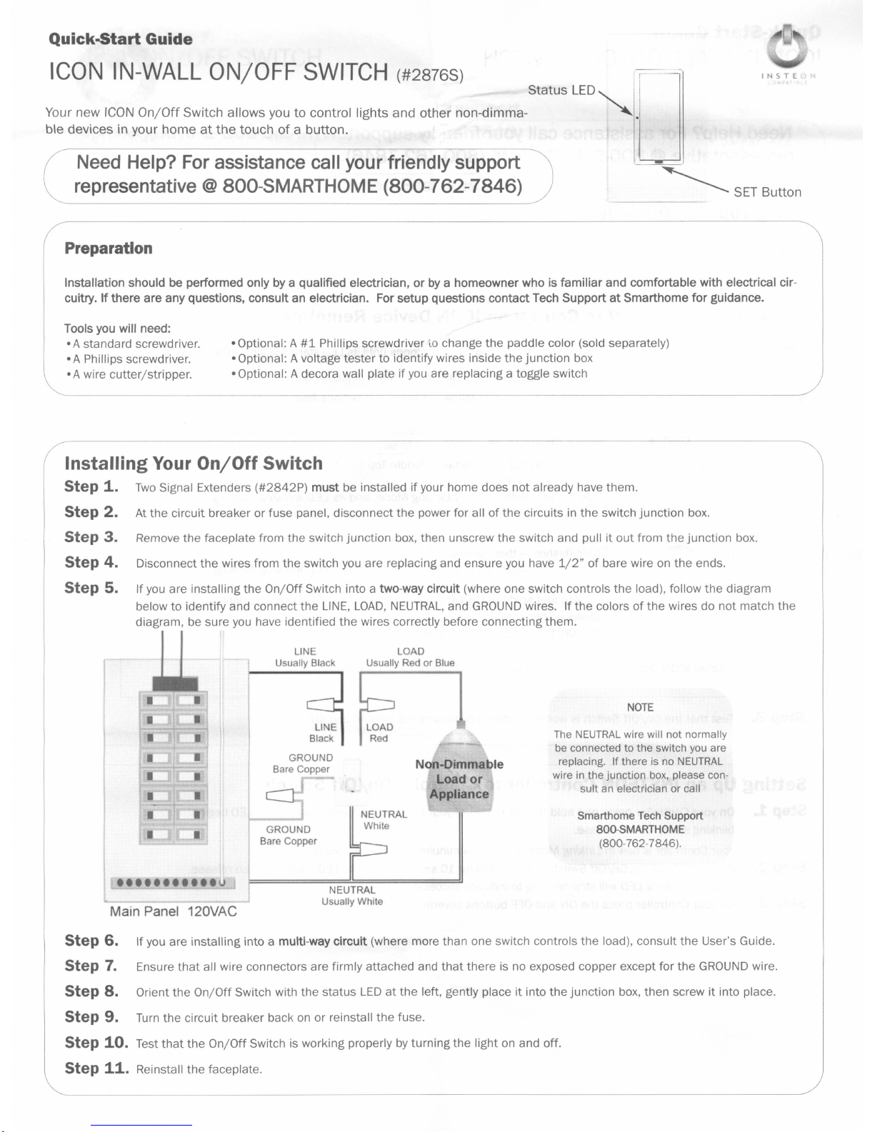
5. Ifyou are installing
below to identify and connect the
diagram,
•••••••••••
Main Panel 120VAC
the circuit breaker or fuse panel, disconnect the power for allofthe circuitsinthe switch junction box.
you
are replacing and ensure
the
On/Off
Switch into a two-way circuit (where one switch controls the load), follow the diagram
LINE,
LOAD,
be
sure
NEUTRAL,
you
have identified the wires correctly before connecting them.
LINE
Usually Black
GROUND
Bare
Copper
Usually
LOAD
RedorBlue
and
Non-Dimmable
Load
Appliance
GROUND
Bare
Copper
u
-
NEUTRAL
Usually White
GROUND
or
you
have
1/2"ofbare wire on
wires. If the colorsofthe wires do
NOTE
The
NEUTRAL
be connected
replacing.
wire in
sult
Smarthome Tech Support
wire will not normally
to
the
If
the
junction
an electricianorcall
800-SMARTHOME
(800-762-7846)
switch you are
there
is no
box, please con-
the
ends.
NEUTRAL
.
not
match the
Step
6.
If you are installing into a multi-way circuit (where more than one switch controls the load), consult the User's Guide.
Step
7.
Ensure
that
all wire connectors are firmly attached and
Step
8.
Orient the
Step
9.
Turn
Step
10.
Test
Step
11.
Reinstall the faceplate.
On/Off
Switch with the status
the circuit breaker backonor reinstall the fuse.
that
the
On/Off
Switch is working properlybyturning the light on and off.
that
there is no exposed copper except for the
LEDatthe left, gently place it into the junction box, then screw it into place.
GROUND
wire.
Page 2
Qulck-5tart
Guide
ICON
IN-WALL
ON/OFF
SWITCH
Need Help? For assistance call your friendlysupport
representative
Using Your
•
Tap
the Paddle
•Tap the Paddle Bottom to turn your load off.
Setting
Step
1.
Step
2.
Top
Up Your
Press and hold the On/Off Switch's Paddle
Your
Select the device you would like to control and follow the setup instructions from thetable below:
In-Wall Dimmer • Press and hold the Dimmer's Paddle
PIUg-ln;,~~.mmer
On/Off Adapter • Press and hold the
@ 800-SMARTHOME (800-762-7846)
On/Off
to turn your load on.
On/Off
DevIce
'li0£:;:;,.
~:,r~
Switch
On/Off
Switch'sisnow in Linking Mode.
~:c";'
'~
t~
i\,;c'
,L
to
Control an
setup Instructions
flashes - then release.
The
On/Off
• Press and hold
trois flashes -
The
On/Off
blinks - then release.
The
On/Off
Switch will exit Linking Mode,
Switch will exit Linking Mode,
Switch will exit Linking Mode,
ICON
Top
for10seconds until its
You
the
Plug-In Dimmer's
then
release.
On/Off
have 4 minutestocomplete Step 2.
Adapter's
Device Remotely
LED
starts blinking - then release.
Top
for10seconds until the light itcontrols
and
its
LED
will stop blinking.
SET
button for 3 seconds until the lampitcon-
and
its
LED
will stop blinking.
SET
button for 3 seconds until its Status
and
its
LED
will stop blinking.
INSTEc>N
COMPATlBLE
LED
Other
ICON
Devices See device's QUick-Start GuideorUser's Guide
Step
3.
Test
that
the
On/Off Switch is working properlybyturning the load on and off.
Setting
Step
Step
Step
Up an
1.
On
blinking slowly - then release.
Your
2.
Press and hold the On/OffSwitch's Paddle
Your
3.
On
INSTEON
your Controller press and hold
Controllerisnow in Linking Mode.
Controller's
your Controller press theONand
LED
Controller
will stop blinking to indicate successful linking.
to
Control a
theONbuttonofyour choice for10seconds until the
You
have 4 minutes to complete step
Top
for10seconds until the
OFF
buttons several timestomake sure everything is working properly.
On/Off
Switch
LED
2.
LED
flashes - then release.
begins
Page 3

Qulck-5tart Guide
IN-WALL
Need
ON/OFF
Help?
For
SWITCH
assistance
call
representative@800-SMARTHOME
Using
To
1. Press and hold the Paddle Top for
2. Press and hold
3.
To
1. Press and hold
2.
3.
Notes
• Pressing
Any
•
Your
unlink a device from yourOn/OffSwitch
On
the
device you wish to unlink, press and hold theONButton for10seconds or
factory resetyour On/Off Switch
Tap
the
Push
the
paddle press will exit Linking Mode early.
SET
SET
the
On/Off
the
Paddle Top again for10seconds - then release.
the
Paddle Top for10seconds - then release.
Button all
Button all
SET
Button after going into Linking Mode will change Linking Mode to Scene Setup (Multi-link) Mode
Switch's Advanced Features
10
seconds - then release.
the
way in - then release.
the
way In and hold for10seconds - then release.
For
detailed instructions on howtooperate all
please refer to the User's Guide
your
friendly
(800-762-7846)
at
http://www.smarthome.com/2876s.html
support
the
SET
Button for 3 seconds.
Xl0 with your
the
featuresofyour On/Off Switch,
NOTE
ICON
products are Xl0 ready. Please
consult
the
user's guide on howtouse
ICON
products.
INSTEc>N
COMPATIBLE
Page 4

Qulck-5tart Guide
ICON
IN-WALL
ON/OFF
SWITCH
Need Help? For assistance call your friendly support
representative
Using
the
On/OffSwitch Virtual Two-way and Multiway Circuits
In
a virtual multi-way circuit, only one On/Off Switch, called the Primary, actually controls the
@ 800-SMARTHOME
tional On/Off Switches, called Secondaries, are not connected to the
NEUTRAL).
All
of the On/Off Switches can communicate with one another using
the On/Off Switches, you create the virtual multi-way circuit
The
diagram below shows how
you
convert a wired-in three-way circuit into a virtual three-way circuit using two On/Off Switches.
LINE
r---1~
Black'
'--.J
LINE
Black
GROUND
Bare Copper
~
I
(800-762-7846)
by
setting up allofthe
TRAVELER
Red'orBlue'
TRAVELER
~~u
1
2
Btack'
Bare Copper
LOAD,
~r---,
L---'
GROUND
but only to the powerline
c:::J::;-
GROUND
Bare Copper
Ii
'f
LOAD
in the multi-way circuit. Anyaddi-
(by
being wired to
INSTEON
networking on the powerline. After wiring in
On/Off Switches to control one another.
LOAD
Red'orBlue'
LOAD
Red
NOTE
Wirecotors
mark.ed with a '
are the usual
and
colors
differIn some
bomes
•..
INSTEc>N
COMPATIBlE
the
LINE
may
and
Main Panel
Notice that one of the
The
other
TRAVELER
TRAVELER2to
TRAVELER
The
Primary's
The
LOAD
the existing
2 to the Primary's
LOAD
wire for any Secondaries
120VAC
TRAVELER
(number 2, the black one)
wire gets connected to the actual lights
wires (number 1, the red one)isnot used, so
LINE
and also to the Secondary's
LINE
wire.
that
you will be installing will not be connected to anything, so cap those
wire nut.
All
On/Off Switches, whether they are Primaries or Secondaries, must be connectedtoNEUTRAL
you
switches
consult an electrician or call Smarthome
Smarthome
Smarthome
form in substantial conformity
C Copyright
aooSMART.HOME .
are replacing will not normally have a connection to
Tech
Um~ed
Warranty
warrantstothe
2005
original consumerofthis product that,
to
the descriptionofthe product in
Smarthome.
16542
949.221.9200
Millikan
• www.smarthome.com
Ave.•Irvine.CA92606-5027
Secondary
you
will convert to a
NEUTRAL
White'
LINE
that
I
Primary
1...-
LINE
wire.Inthe junction box where the Secondary
wire.Inthe other junction boxatthe other end,
are being controlled.
---..1
you
will capitoffatboth ends with a wire nut.
LOAD
andtoGROUND.
NEUTRAL.
Ifthere is no
NEUTRAL
wire in
the
junction
Support, 800-SMARTHOME (800-762-7846).
for
a periodofone year from the dateofpurchase, this product will be free from defects in material and workmanship
the
owner's manual. This warrantyshall
not
apply to defectsorerrors causedbymisuseorneglect.
you
will connect
wires
Note
is,
off
that
box,
connect
with a
the
please
and
will per-
rev.
121905
 Loading...