

Page 1
®
INSTEON Door Sensor 2845-x22
®
INSTEON Door Sensor 2845-x22
Owner’s Manual
Owner’s Manual
Page 2

Contents
Getting Started
INSTEON Hidden Door Sensor 4
Device Overview
Tools Needed for Installation
Test Your Location First
Install in a Window Frame
Installation
Link First 6
Locate the Hole
Drill the Hole
Test the Fit
Using the Spacer 7
INSTEON Links
Understanding Linking 9
Linking to the INSTEON Hub 11
Linking to Control Another Device 12
Already Installed Linking 13
Multi-Linking or Making a Scene 15
Unlinking a Device 16
Multi-Unlinking or Removing a Scene 17
Local Programming
Local Programming 20
Factory Reset
Factory Reset 23
Software-Only Features
Enable Group 1 & 2 Broadcast 25
Disable Local Programming
Disable LED and Beeper
Adjust Heartbeat Interval
Low Battery Warning 26
Appendix
Specications 29
Troubleshooting 32
Certications and Warnings 33
Product Warranty 35
Page 3
Getting Started
Getting Started
Everything you need to quickly get up and running.
Everything you need to quickly get up and running.
3
Page 4
X
X
Contact
Plunger
Set
Button
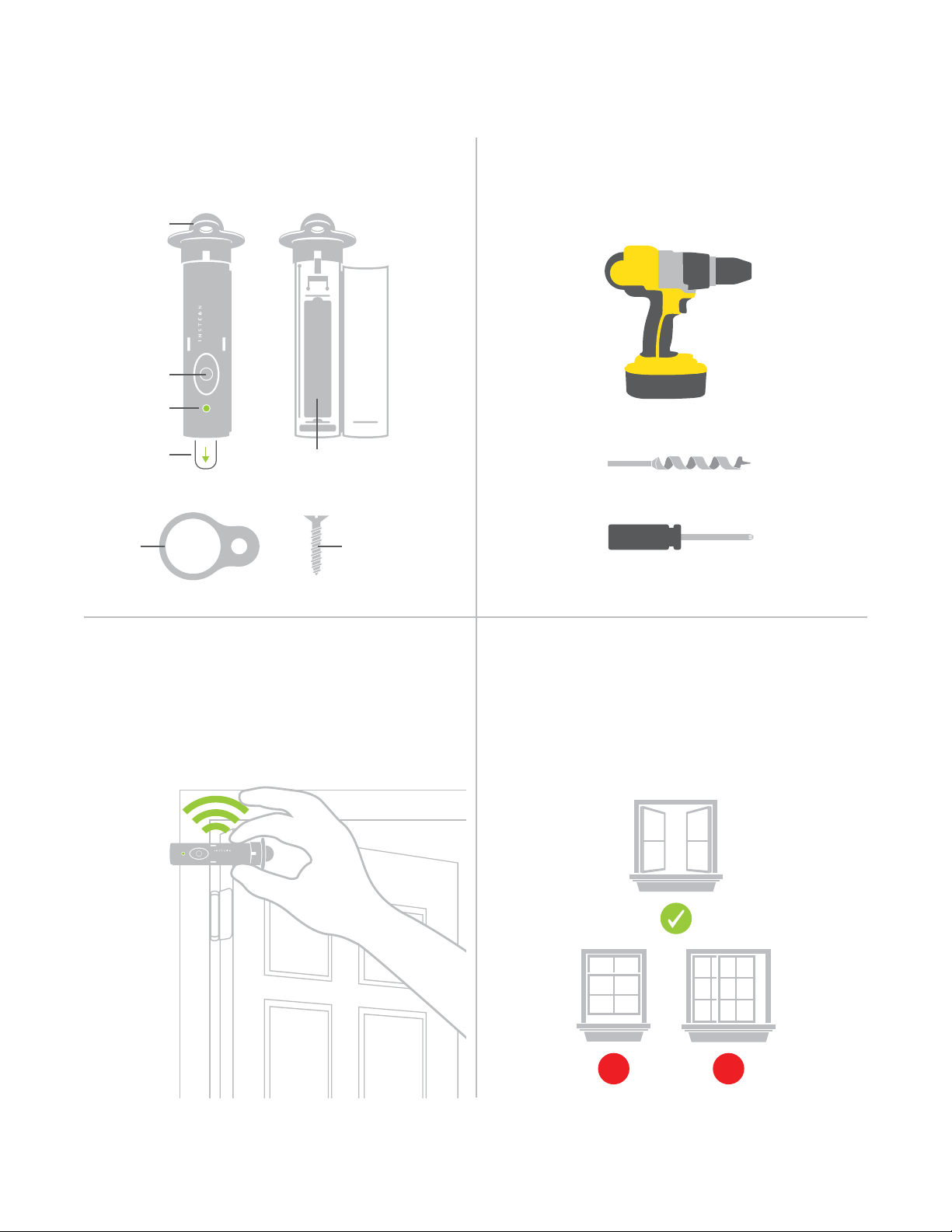
INSTEON Hidden Door Sensor
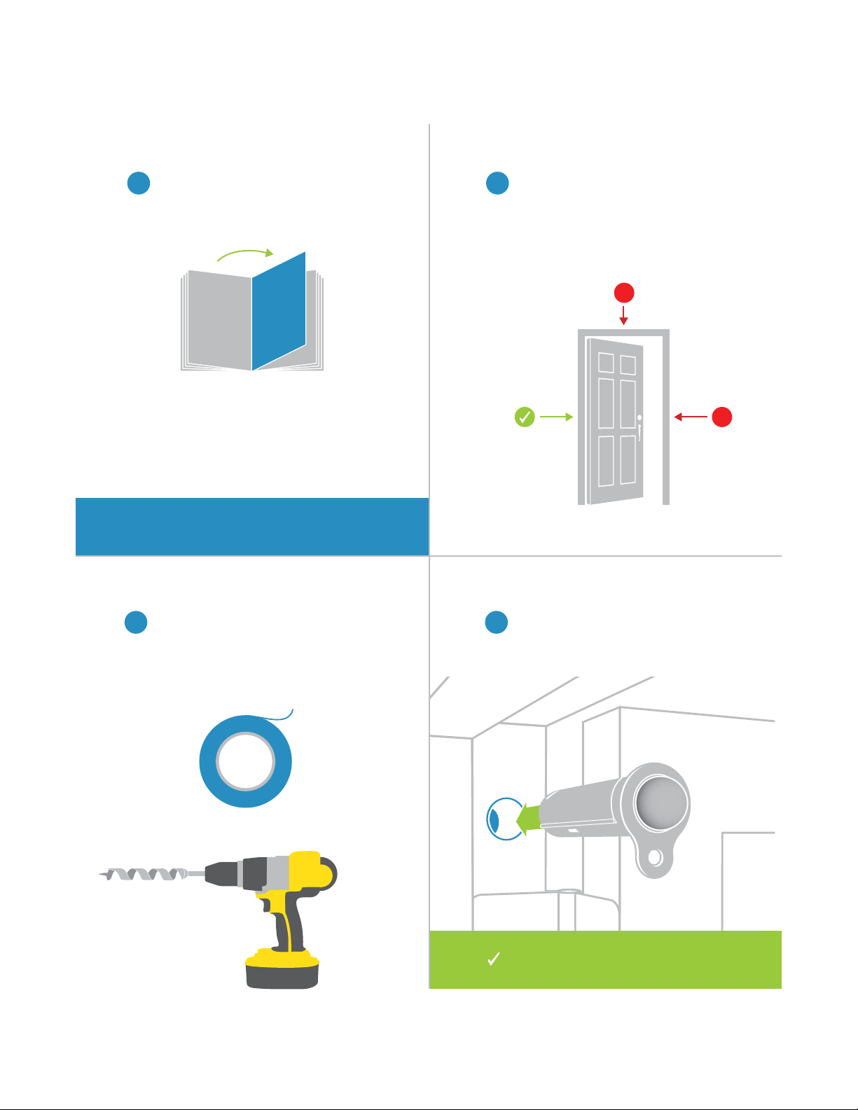
Device Overview Tools Needed for Installation
®
Model: 2845-222
Door Sensor
Status
LED
Battery Isolation Tab
(Remove before rst use)
Spacer Spacer Screw
Test your desired location rst. Hold the
Door Sensor in it’s intended location and try
linking to your Hub or responder. If linking is
unsuccessful, try repositioning the sensor or
add a Range Extender.
Power Drill
AAA Battery
(Included)
3/4-inch Auger Drill Bit
(Recommended)
Phillips Screwdriver
Test Your Location First Install in a Window Frame
If installing in a window frame, Door Sensor
works best with casement windows. Follow
the same installation steps. INSTEON
recommends using Open/Close Sensor
(2843-222) for sash windows.
®
Door Sensor
Model: 2845-222
4
Page 5
Installation
Installation
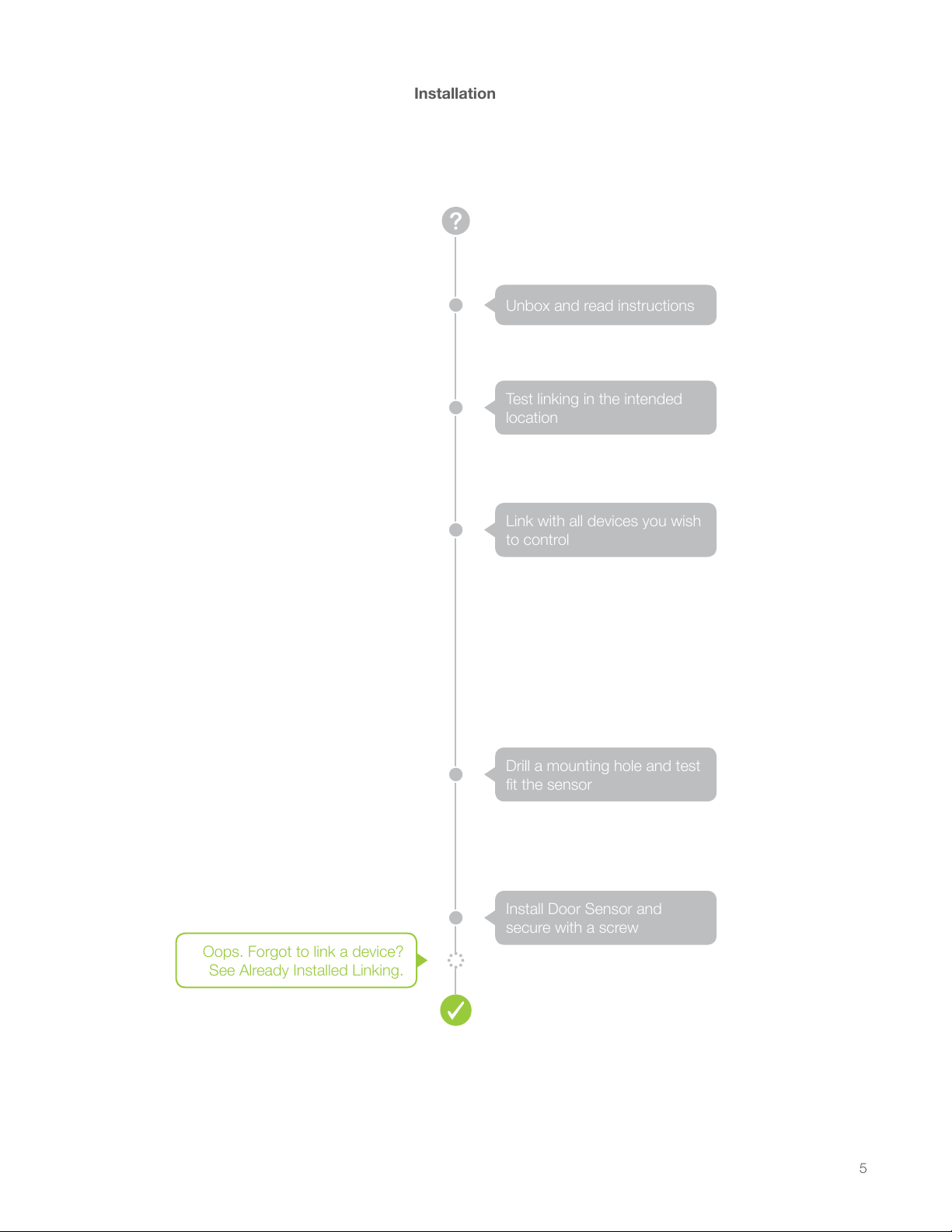
Unbox and read instructions
Unbox and read instructions
Test linking in the intended
Test linking in the intended
location
location
Link with all devices you wish
Link with all devices you wish
to control
to control
Oops. Forgot to link a device?
Oops. Forgot to link a device?
See Already Installed Linking.
See Already Installed Linking.
Drill a mounting hole and test
Drill a mounting hole and test
t the sensor
t the sensor
Install Door Sensor and
Install Door Sensor and
secure with a screw
secure with a screw
5
Page 6
Installation
X
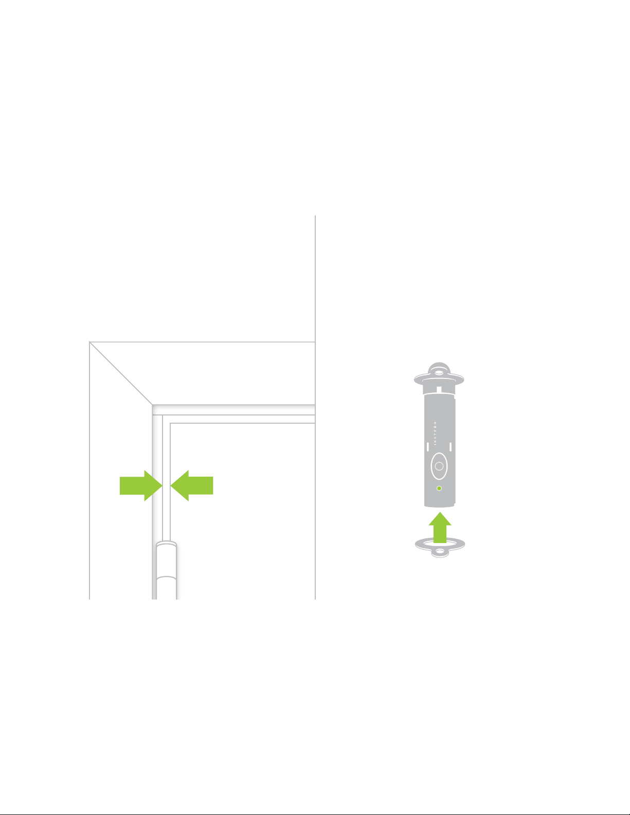
Link First Locate the Hole
As installing Door Sensor obscures its
1 2
set button, perform any linking now
before you install the sensor.
For linking instructions, turn to Page 9.
Find a location for Door Sensor in
either the hinge-side of the door frame
or the hinge-side of the door itself.
Higher is better for wireless range but
low will still work.
X
If you skip linking now, you can link
?
later using Five-Tap linking.
Place masking tape over any surfaces
that may be marred by the drill chuck
and drill a 4-inch deep, ¾-inch diameter
hole. If drilling into the door, have an
assistant hold the door steady.
Test the FitDrill the Hole
Clean out any wood shavings with a
43
vacuum and test t the sensor. When
ready, insert the sensor into the hole
and fasten with the included screw.
Installation of your Door Sensor is
now complete.
6
Page 7
Using the Spacer
If the gap between your door and door
frame is too wide to depress the contact
plunger, try using the spacer.
Slide the spacer over Door Sensor to
increase the thickness of the collar. Fasten
with the screw provided.
®
Model: 2845-222
Door Sensor
7
Page 8
INSTEON Links
INSTEON Links
INSTEON devices can stand alone and function as a local switch or
INSTEON devices can stand alone and function as a local switch or
dimmer, but their real power comes when they are connected together to
dimmer, but their real power comes when they are connected together to
form a control system. Most INSTEON devices can control one another
form a control system. Most INSTEON devices can control one another
and be the recipient of control. The process of associating multiple
and be the recipient of control. The process of associating multiple
INSTEON devices to one another is called Linking.
INSTEON devices to one another is called Linking.
8
Page 9
NEW
NEW
75%
NEW
NEW
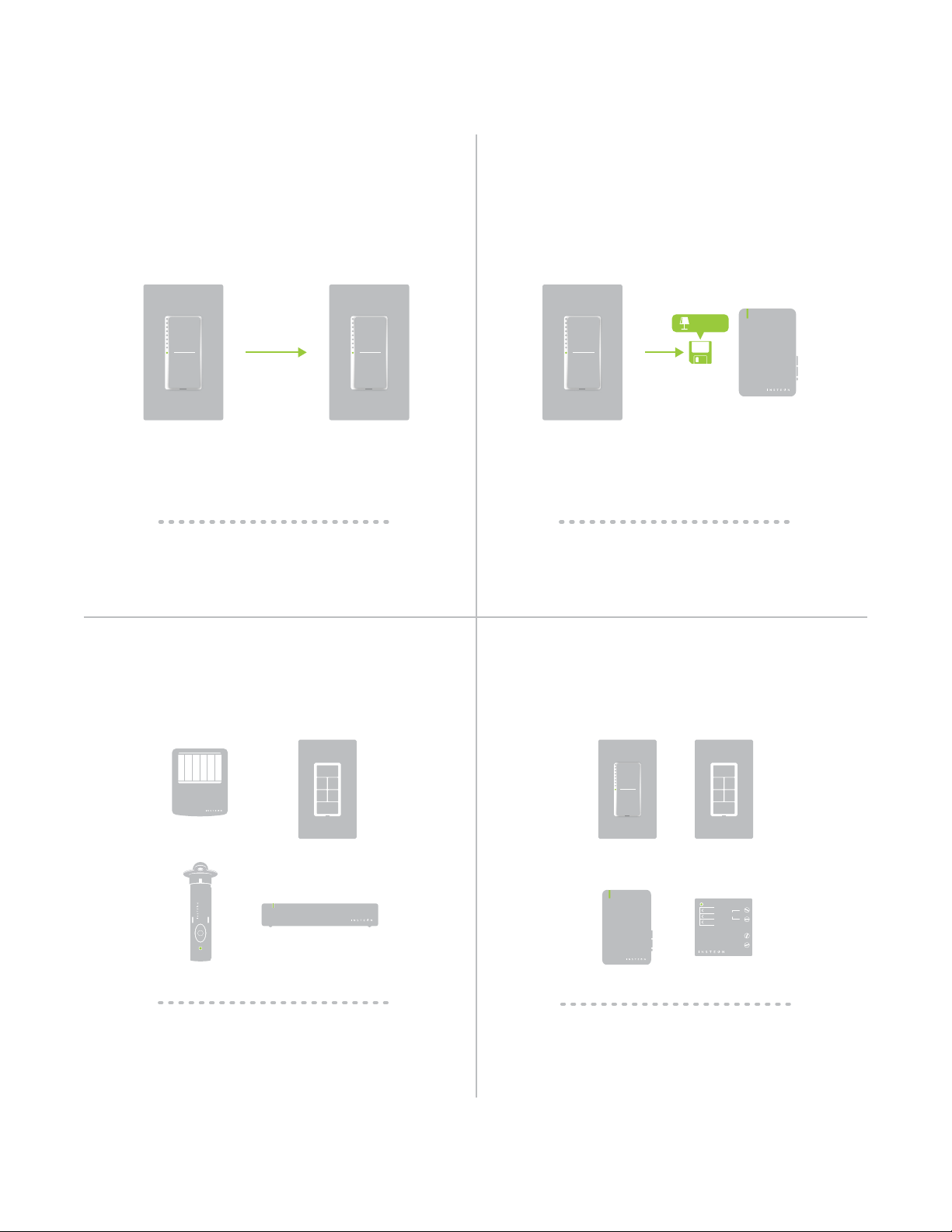
Understanding Linking
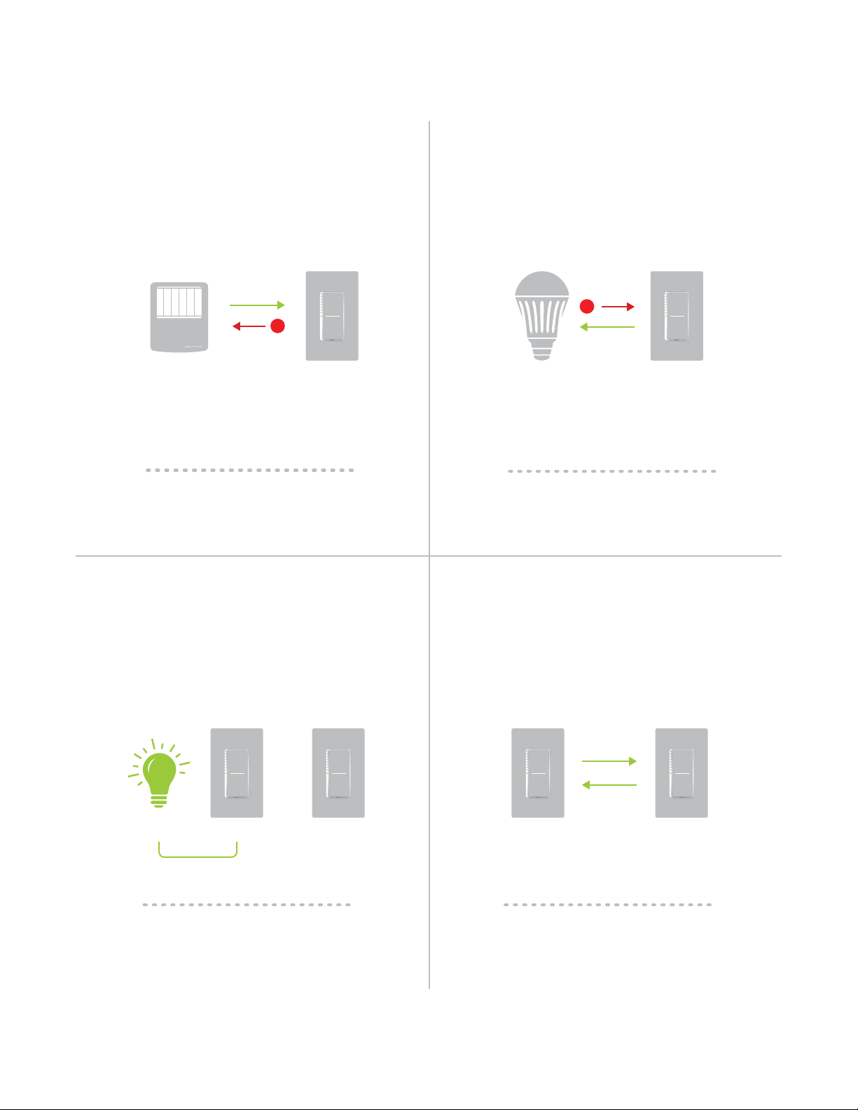
Links Remember a Device’s StateLinks are One-Way
When linking INSTEON devices, the links that
are created are one-way.
A SwitchB Lamp Dimmer
The current state of the controlled device is
stored in the link: On, off or dimmed.
®
Switch A will turn Switch B on and off but
Switch B cannot turn Switch A on or off.
INSTEON devices that can turn other devices
on or off are called controllers.
®
®
Model: 2845-222
Door Sensor
®
The switch will turn on the Lamp Dimmer to
75% brightness.
RespondersControllers
INSTEON devices that receive the command of a
controller are called responders.
N
On
Neutral
Off
N
Set
Load L1
Line L
®
®
Sensors, Switches, Keypads and the
Hub are common controllers.
Switches, Keypads, Plug-In Modules and
In-Line Modules are common responders.
9
Page 10
NEW
NEW
X
Understanding Linking
NEW
NEW
X
Controller-Only
Some devices, like sensors, can only control
other devices.
®
Motion Sensor
The Motion Sensor will turn on the Switch
but the switches cannot control the Motion
Sensor.
Dimmer Switch
Responder-Only
Some devices cannot control other devices;
these devices only receive INSTEON commands.
LED Bulb Dimmer Switch
Some devices can only link as
responders to devices and scenes.
Grouping Devices Use Cross Linking
You may want to group together two
devices, for example, in a virtual-three way
conguration. For INSTEON, this is called
Cross Linking.
A BLoad
To mirror Switch A and B so that they each
control one another and the connected
load, Cross Linking is necessary.
To Cross Link, simply turn on the devices and
perform the linking process twice, once in
each direction.
A B
Link Switch A to Switch B and repeat to link
Switch B to Switch A.
10
Page 11
Linking to the INSTEON Hub
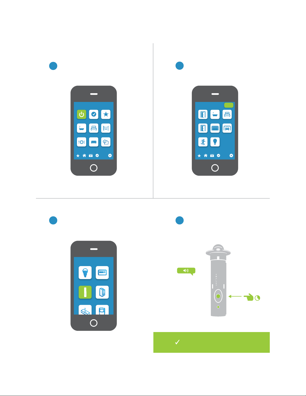
From Rooms, navigate to All Devices.
1
Rooms
All Devices Check-In Favorites
Bathroom Bedroom Hallway
Kitchen Living Room Outside
72º
Tap the Add button.
2
Back Door Bathroom Bedroom
Font Door Garage Door Garage Light
Motion Sensor Outside Lights
All Devices
Add
72º
Select Door Sensor from the list of
3 4
devices.
Add Device
LED Bulb Thermostat
Door Sensor
Open/Close
Sensor
When prompted, press and hold the
set button on your Door Sensor until
the device beeps.
®
Model: 2845-222
Door Sensor
Your Door Sensor is now added
to your INSTEON Hub.
11
Page 12

Linking to Control Another Device
On your Door Sensor, press and
1
hold the set button until the device
beeps.
®
Model: 2845-222
Door Sensor
Adjust your responder to the desired
2
state: On, off, or brightness level if
dimming, and then press and hold the set
button until the device double-beeps.
®
®
Model: 2845-222
Door Sensor
®
Your INSTEON controller will now
control your On/Off Module.
12
Page 13

Already Installed Linking
Link Hidden Door Sensor without removing from your door frame
If Your Door Is Already Open If Your Door Is Closed
Press and release Door Sensor’s contact
1
plunger twice then hold the contact
plunger until Door Sensor beeps.
Open your door and press and release
Door Sensor’s contact plunger twice. After
a pause, Door Sensor will beep.
OR
Once in linking mode, you can open
or close the door without exiting
linking mode.
You can cycle between Linking and
??
Unlinking by repeating the Five-Tap
Linking process.
Linking
Unlinking
Exit
13
Page 14

Link Hidden Door Sensor without removing from your door frame
Adjust your responder to the desired
2
state: On, off, or brightness level
if dimming, and then press and
hold the set button until the device
double-beeps.
Already Installed Linking
®
Model: 2845-222
Door Sensor
®
®
Your INSTEON controller will now
control your On/Off Module.
14
Page 15

Multi-Linking or Making a Scene
On your Door Sensor, press and
1
hold the set button until the device
beeps then tap the set button.
®
Model: 2845-222
Door Sensor
Adjust your scene members to
2
their desired state: On, off, or
brightness level if dimming.
50% 72%
Lamp 1
30%
Lamp 2
ON
A
B
Lamp 3
Appliance
One at a time, press and hold the
3 4
set button on each scene member
until it double-beeps.
®
Tap the set button on your Door
Sensor to nish building your scene.
®
Model: 2845-222
Door Sensor
ONCE
Your Door Sensor will now control
your scene.
15
Page 16

Unlinking a Device
X
On your Door Sensor, press and
1
hold the set button until the device
beeps.
®
Model: 2845-222
Door Sensor
Press and hold the set button
2
again until the device beeps .
®
Model: 2845-222
Door Sensor
Press and hold the controlled
3
device’s set button until the device
double-beeps.
®
®
Model: 2845-222
Door Sensor
®
Your Door Sensor will no longer
control your INSTEON device.
16
Page 17

Multi-Unlinking or Removing a Scene
On your Door Sensor, press and
1
hold the set button until the device
beeps.
®
Model: 2845-222
Door Sensor
Press and hold the set button
2
again until the device beeps.
®
Model: 2845-222
Door Sensor
Tap the set button. Press and hold the controlled
3 4
device’s set button until the device
double-beeps.
®
Model: 2845-222
Door Sensor
®
17
Page 18

Tap the set button on your Door
X
5
Sensor to exit Multi-Unlinking
mode.
Multi-Unlinking or Removing a Scene
®
®
Model: 2845-222
Door Sensor
®
Model: 2845-222
Door Sensor
®
®
Your Door Sensor will no longer
control your INSTEON responders.
18
Page 19

Local Programming
Local Programming
Encompassing all on-device programming options, use the local
Encompassing all on-device programming options, use the local
programming to set local properties and factory reset. For the best
programming to set local properties. For the best experience, use
experience, use software for managing device properties.
software for managing device properties.
19
Page 20

Local Programming is a visual representation
NEW
of the device’s settings. Many device features
can be congured using the ow chart. Some
devices have more options than others but the
programming wheel presents even the most
complicated devices with a straightforward,
navigable path.
Local Programming
NavigationAbout the Flow Chart
To move right, press and
hold the set button
To move down, tap the set
button
Status LED blinks green
Status LED double-blinks
green
Status LED blinks red
Status LED double-blinks
red
Local Programming Features
Linking Mode Readies the module for linking to another INSTEON module. As linking is directional,
the rst device placed into linking mode will become the controller in the controller/
responder relationship. The second device will become the responder. The device
automatically exits linking mode after a link has been made with another INSTEON
device.
Multi-Linking Mode Readies the module for linking to multiple INSTEON modules. The module will remain in
linking mode for 4 minutes or until the module’s set button is tapped. This mode is very
usefully for manually creating scenes.
Unlinking Mode Allows the removal of links from the INSTEON module. The device will automatically exit
unlinking mode after a link has been removed from another INSTEON device.
Multi-Unlinking Mode Allows the removal of multiple links from the INSTEON module. The device will stay in
unlinking mode for 4 minutes or until the device’s set button is tapped.
20
Page 21

Local Programming
®
Model: 2845-222
Door Sensor
Press
Tap
Multi-Linking
Linking Mode
Mode
Press
Exit
Unlinking
Mode
MultiUnlinking
Mode
Press
Exit
Tap
Press
Exit
TapTap
ExitExit
21
Page 22

Factory Reset
Factory Reset
A factory reset will erase all links stored in the device’s database as well as
A factory reset will erase all links stored in the device’s database as well as
any customized properties.
any customized properties.
22
Page 23

®
Door Sensor
Model: 2845-222
®
Door Sensor
Model: 2845-222
Factory Reset
Remove Door Rensor from the
1
door frame and take out the
sensor’s battery.
Press and hold the set button
2
while reinstalling the battery.
LONG
Continue to hold the set button
3
until the long beep stops. Let
go and Door Sensor will emit a
double-beep.
®
Model: 2845-222
Door Sensor
Your Door Sensor has been
restored to factory settings.
23
Page 24

Software-Only Features
Software-Only Features
Most INSTEON devices contain features that can only be enabled,
Most INSTEON devices contain features that can only be enabled,
disabled or modied using INSTEON control software such as HouseLinc
disabled or modied using INSTEON control software such as HouseLinc
and an INSTEON PowerLine Modem.
and an INSTEON PowerLine Modem.
24
Page 25

Software-Only Features
X
Enable Group 1 & 2 Broadcast Disable Local Programming
When enabled, Door Sensor will send a
separate On for opening and for closing.
Useful if you want a device to turn on when
the door closes, like a bathroom fan.
Prevents changing any settings using the set
button or tap-and-hold programming.
Group 1 ON Group 2 ON
®
Model: 2845-222
Door Sensor
Disable LED and Beeper Adjust Heartbeat Interval
The status LED will not blink when the
sensor is triggered and the beeper will not
respond to button presses.
®
Model: 2845-222
Door Sensor
Customize the duration of time between
sensor check-ins; by default, the sensor will
broadcast it’s state once every 24 hours.
®
Door Sensor
Model: 2845-222
25
Page 26

Low Battery Warning
Enable or disable a low battery broadcast
that can trigger events with software.
Software-Only Features
26
Page 27

Appendix
Appendix
Everything else you might need to know about your INSTEON product.
Everything else you might need to know about your INSTEON product.
27
Page 28

INSTEON Glossary
Controller The INSTEON transmitter
Responder The INSTEON receiver
Blinking LED turning on and off repeatedly
Dual-Band An INSTEON device that can send and receive both INSTEON powerline signals and
INSTEON radio frequency signals
Ramp Rate The speed at which the load fades on or off
On-Level The preset brightness level a device will return to when turned on
INSTEON A dual-band, mesh networking technology developed by Smarthome/INSTEON. The world’s
most reliable, expandable and simple home automation and control technology.
Link A one way association between a controller and responder
Linking A method for associating INSTEON controller buttons with groups of INSTEON responders
such that the responders instantly return to a memorized state when the button is pushed.
Links can be made manually with the set button or using software.
Unlinking The process by which an INSTEON device can remove stored links. Just as with linking,
unlinking is a one-way process and should be performed in both directions for devices that
are both controllers and responders of each other, as in a 3-way switch scenario.
Multi-Linking
/ Unlinking
Factory Reset A process that erases all stored links and recongures the device to factory defaults.
Load The device that you are controlling (e.g. a light bulb, ceiling fan, etc.)
On/Off A device that can control its connected load to turn on and off but cannot dim. Usually a
Retry A 2nd (or subsequent) attempt by a controller to send an INSTEON signal, usually after an
Scene Multiple devices respond to memorized states. For example, a dinner time scene turns
Set Button A button on an INSTEON device that is used for setting or changing its properties
Simulcast A method for increasing the reliability of message delivery in a network. When a node in
A special mode that allows more than one link to be either created or removed
simultaneously, without laborious set button presses. When in linking or unlinking mode, an
INSTEON device will continue to link to other devices until the set button is tapped or four
minutes have elapsed, whichever occurs rst.
relay-based device.
acknowledge is not received from the responder in the expected time-slot.
on the dining table light, dims the kitchen lights to 10%, backyard lights turn off and the
thermostat adjusts to 72º.
a network sends a message, every other node that hears the message retransmits it at
precisely the same time based on a global clock, provided that the message has not already
been retransmitted some maximum number of times. Message propagation is more robust
because each node adds its energy to the signal, much like voices in a choir. Simulcasting
is much simpler than message routing because there are no routing tables to maintain and
nodes can join the network without any installation procedure.
X10 A legacy powerline networking technology. Many INSTEON devices are backwards
compatible with X10 devices by setting a house and unit code.
28
Page 29

General
Specications
Available Colors White
Brand INSTEON
FCC ID SPB28452
Industry Canada 5202A-28452
Product Number. 2845-222 US
2845-422 EU
2845-522 AUS/NZ
Patent Protected under US and Freign Patents (see www.insteon.com/
patents)
UPC 813922013092 US
813922013603 EU
813922013610 AUS/NZ
Warranty 2 years, limited
Operation
Audio Alert Beeper, can be disabled through software
Operation Modes INSTEON only
Operational Gap Direct contact with contact plunger required
Setup Memory Non-volatile EEPROM
Status LED Red/Green LED
INSTEON Features
INSTEON Addresses 400
INSTEON Device Category 0x10
INSTEON Device Subcategory 0x11 US
INSTEON ID 1
INSTEON Links 417
0x14 EU
0x15 AUS/NZ
INSTEON Messages Repeated No
INSTEON Powerline Device No
INSTEON RF Device Ye s
Maximum Controlled Scenes 2
29
Page 30

Maximum Scene Memberships 1
Multi-Link Support Ye s
Multi-Unlink Support Ye s
Phase Detect Beacon No
Radio Frequency 915 MHz US
Radio Frequency Range 150 feet
Specications
869.85 MHz EU
921 MHz AUS/NZ
Scene Commands Supported as
Scene Commands Supported as
Responder
Software Congurable Ye s
Mechanical
Switch Type Momentary mechanical switch
Dimensions 0.75” diameter, 3.4” length
Enclosure Material Plastic
Operating Environment Indoors
On Off
Controller
None
15.9mm diameter, 87mm length
Mounting 0.75” diameter, 3.1” deep hole in door frame or door
19mm diameter, 79mm deep hole in door frame or door
Operating Humidity Range 0-90% relative humidity, non-condensing
Operating Temperature Range -40º to 104º F
-40º to 40º C
Set Button 1, recessed. Requires removal of sensor to access
Storage Temperature Range -40º to 104º F
-40º to 40º C
Weight 0.64 oz
20g
30
Page 31

Electrical
Battery Type AAA
Battery Life 6 months
Certication N/A, Battery-powered device
Power Consumption 60μA
Supply Voltage 1.5V DC (AAA Battery)
X10 Features (Powerline Only)
X10 Support No
Specications
31
Page 32

Troubleshooting
Door Sensor won’t link to other INSTEON Devices
Your Door Sensor may be out of range of a dual-band INSTEON device or your network may be powerline-only.
Try this:
• If your INSTEON network lacks any dual-band devices, add a Range Extender or other dual-band INSTEON
device near your Door Sensor to bridge the INSTEON RF and powerline networks.
• Door Sensor must be placed within 100’ of a dual-band device. Radio interference and building
construction may reduce range. Relocate a dual-band device or add a Range Extender to increase RF
coverage.
Status LED ashes rapidly after triggering Door Sensor’s contact plunger
While you can only see the Status LED when Door Sensor is removed from the door frame, this blinking
indicates that Door Sensor may have not received acknowledgment from one or more linked devices.
Try this:
• If you have removed any INSTEON devices from your network that were previously controlled by Door
Sensor, unlink them from Door Sensor. If the removed device is no longer available, use software to remove
the link from Door Sensor’s link table or perform a factory reset to clear all links.
• Door Sensor may be on the fringe of your INSTEON RF network. Add an additional INSTEON dual-band
device or Range Extender near Door Sensor for improved RF and powerline signal bridging.
Status LED does not ash when the set button is tapped or when the contact plunger is depressed
Your Door Sensor’s battery may be low and require replacement.
Try this:
• Remove Door Sensor from the retention collar and try a different AAA battery.
Hidden Door Sensor makes a hissing noise when installing a new battery
A faint hissing noise can often be heard when removing the battery isolation tab or installing a new battery.
Try this:
• This is normal operating behavior for Hidden Door Sensor. The noise is part of the startup diagnostics
performed by the sensor..
32
Page 33

Certications and Warnings
This device complies with FCC Rules and Industry Canada license-exempt RSS standard(s). Operation is
subject to the following two conditions: (1) this device may not cause harmful interference, and (2) this device
must accept any interference, including interference that may cause undesired operation of the device.
Le present appareil est conforme aux CNR d’Industrie Canada applicables aux appareils radio exempts
de licence. L’exploitation est autorise aux deux conditions suivantes: (1) l’appareil ne doit pas produire de
brouillage, et (2) l’utilisateur de l’appareil doit accepter tout brouillage radiolectrique subi, mme si le brouillage est
susceptible d’en compromettre le fonctionnement.
Changes or modications to this unit voids the user’s authority to operate this product and the manufacturer’s
warranty.
The digital circuitry of this device has been tested and found to comply with the limits for a Class B digital
device, pursuant to Part 15B of the FCC Rules. These limits are designed to provide reasonable protection
against harmful interference in residential installations. This equipment generates, uses, and can radiate
radio frequency energy and, if not installed and used in accordance with the instructions, may cause harmful
interference to radio and television reception. However, there is no guarantee that interference will not occur in a
particular installation. If this device does cause such interference, which can be veried by turning the device off
and on, the user is encouraged to eliminate the interference by one or more of the following measures:
- Re-orient or relocate the receiving antenna of the device experiencing the interference
- Increase the distance between this device and the receiver
- Connect the device to an AC outlet on a circuit different from the one that supplies power to the receiver
- Consult the dealer or an experienced radio/TV technician
WARNING: Changes or modications to this device not expressly approved by the party responsible for
compliance could void the user’s authority to operate the equipment.
DECLARATION OF CONFORMITY
Hereby, INSTEON declares that this device is in compliance with the essential requirements and other relevant
provisions of the following Directives:
1) Electromagnetic Compatibility Directive 2004/108/EC
2) Hazardous Substance Directive 2005/95/EC
Technical data and copies of the original Declaration of Conformity are available and can be obtained from
INSTEON; 16542 Millikan Ave, Irvine, CA, USA.
User Information for Consumer Products Covered by EU Directive 2002/96/EC on Waste Electric and Electronic
Equipment (WEEE)
This document contains important information for users with regards to the proper disposal and recycling of
INSTEON products. Consumers are required to comply with this notice for all electronic products bearing the
following symbol:
Environmental Information for Customers in the European Union
European Directive 2002/96/EC requires that the equipment bearing this symbol on the product and/or its
packaging must not be disposed of with unsorted municipal waste. The symbol indicates that this product
should be disposed of separately from regular household waste streams.
33
Page 34

Certications and Warnings
It is your responsibility to dispose of this and other electric and electronic equipment via designated collection
facilities appointed by the government or local authorities. Correct disposal and recycling will help prevent
potential negative consequences to the environment and human health.
For more detailed information about the disposal of your old equipment, please contact your local authorities,
waste disposal service, or the shop where you purchased the product.
DECLARATION OF CONFORMITY TO R&TTE DIRECTIVE 1999/5/EC for the European Community, Switzerland,
Norway, Iceland and Liechtenstein
Product category: general consumer (category 3).
English: This equipment is in compliance with the essential requirements and other relevant provisions of the
European R&TTE Directive 1999/5/EC
Deutsch [German]: Dieses Gerät entspricht den grundlegenden Anforderungen und den weiteren
entsprechenden Vorgaben der Richtlinie 1999/5/EU.
Nederlands [Dutch]: Dit apparaat voldoet aan de essentiele eisen en andere van toepassing zijnde bepalingen
van de Richtlijn 1999/5/EC.
Svenska [Swedish]: Denna utrustning står I överensstämmelse med de väsentliga egenskapskrav och övriga
relevanta bestämmelser som framgår av direktiv 1999/5/EG.
Français [French]: Cet appareil est conforme aux exigences essentielles et aux autres dispositions pertinentes de
la Directive 1999/5/EC
Español [Spanish]: Este equipo cumple con los requisitos esenciales asi como con otras disposiciones de la
Directiva 1999/5/CE.
Português [Portuguese]: Este equipamento está em conformidade com os requisitos essenciais e outras
provisões relevantes da Directiva 1999/5/EC. Italiano [Italian]: Questo apparato é conforme ai requisiti essenziali
ed agli altri principi sanciti dalla Direttiva 1999/5/CE.
Norsk [Norwegian]: Dette utstyret er i samsvar med de grunnleggende krav og andre relevante bestemmelser i
EU-direktiv 1999/5/EF.
Suomi [Finnish]:Tämä laite tÿttää direktiivin 1999/5/EY olennaiset vaatimukset ja on siinä asetettujen muiden
laitetta koskevien määräysten mukainen. Dansk [Danish]: Dette udstyr er i overensstemmelse med de væsentlige
krav og andre relevante bestemmelser i Direktiv 1999/5/EF.
Polski [Polish]: Urządzenie jest zgodne z ogólnymi wymaganiami oraz szczególnymi warunkami okreslonymi
Dyrektywą UE: 1999/5/EC
34
Page 35

Product Warranty
Limited Warranty
Seller warrants to the original consumer purchaser of this product that, for a period of two years from the date
of purchase, this product will be free from defects in material and workmanship and will perform in substantial
conformity to the description of the product in this Owner’s Manual. This warranty shall not apply to defects or
errors caused by misuse or neglect. If the product is found to be defective in material or workmanship, or if the
product does not perform as warranted above during the warranty period, Seller will either repair it, replace it,
or refund the purchase price, at its option, upon receipt of the product at the address below, postage prepaid,
with proof of the date of purchase and an explanation of the defect or error. The repair, replacement, or refund
that is provided for above shall be the full extent of Seller’s liability with respect to this product. For repair or
replacement during the warranty period, call 866-243-8022 with the Model # and Revision # of the device to
receive an RMA# and send the product, along with all other required materials to:
INSTEON
ATTN: Receiving
16542 Millikan Ave.
Irvine, CA 92606-5027
Limitations
The above warranty is in lieu of and Seller disclaims all other warranties, whether oral or written, express or
implied, including any warranty or merchantability or tness for a particular purpose. Any implied warranty,
including any warranty of merchantability or tness for a particular purpose, which may not be disclaimed
or supplanted as provided above shall be limited to the two-year of the express warranty above. No other
representation or claim of any nature by any person shall be binding upon Seller or modify the terms of the
above warranty and disclaimer.
Home automation devices have the risk of failure to operate, incorrect operation, or electrical or mechanical
tampering. For optimal use, manually verify the device state. Any home automation device should be viewed as
a convenience, but not as a sole method for controlling your home.
In no event shall Seller be liable for special, incidental, consequential, or other damages resulting from
possession or use of this device, including without limitation damage to property and, to the extent permitted by
law, personal injury, even if Seller knew or should have known of the possibility of such damages. Some states
do not allow limitations on how long an implied warranty lasts and/or the exclusion or limitation of damages, in
which case the above limitations and/or exclusions may not apply to you. You may also have other legal rights
that may vary from state to state.
Protected under U.S. and foreign patents (see www.insteon.com/patents)
© Copyright 2013 INSTEON
Rev 11.22.13
35
 Loading...