

Page 1
Open/Close Sensor
Owner’s Manual
Hardware Revision 1.9+
2843-222 (US)
2843-422 (EU)
2843-522 (AUS/NZ)
Page 1 of 9 2843-222/2843-422/2843-522 - Rev: 1/21/2014 7:18 AM
Page 2
In the Box
Tools Needed
Optional Accessories
Open/Close Sensor
None
INSTEON Hub
Magnet Mini Remote
Quick Start Guide
One (1) AA Battery
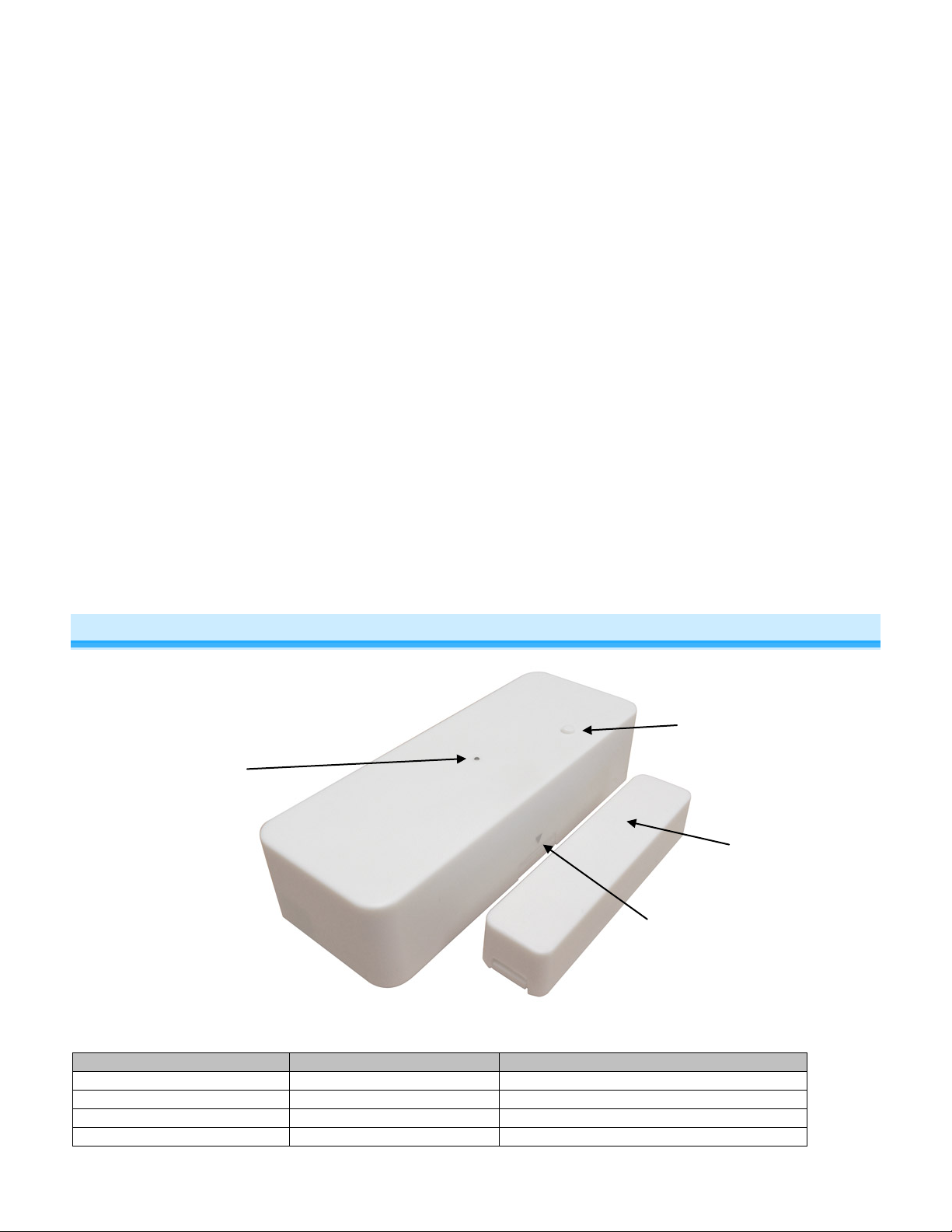
Status LED
Set Button
Magnet
Indicator arrows
About Open/Close Sensor ............................................................................................................................................ 2
Open/Close Sensor Hardware ..................................................................................................................................... 3
Installation ..................................................................................................................................................................... 3
Install Open/Close Sensor ........................................................................................................................................... 3
Connecting an External Sensor to Open/Close Sensor .............................................................................................. 4
INSTEON Setup ............................................................................................................................................................. 4
INSTEON Controllers, Responders and Links ............................................................................................................ 4
Default Mode ............................................................................................................................................................... 4
Make Open/Close Sensor a Controller ........................................................................................................................ 5
Make Open/Close Sensor a Controller of Multiple Responders .................................................................................. 5
Remove Open/Close Sensor as a Controller .............................................................................................................. 5
Using Open/Close Sensor’s Multi-Scene Mode .......................................................................................................... 5
Linking in Multi-Scene Mode ....................................................................................................................................... 6
Unlinking in Multi-Sce ne Mode .................................................................................................................................... 6
Scenes ............................................................................................................................................................................ 6
Advanced Features ....................................................................................................................................................... 6
Advanced External Sensor Use ................................................................................................................................... 6
Power Restore ............................................................................................................................................................. 7
Factory Reset .............................................................................................................................................................. 7
Specifications ................................................................................................................................................................ 7
Certification and Warranty ........................................................................................................................................... 8
FCC and Industry Canada Compliance Statement ..................................................................................................... 8
Declaration of Conformity ............................................................................................................................................ 9
Limited Warranty .......................................................................................................................................................... 9
Limitations .................................................................................................................................................................... 9
About Open/Close Sens or
Page 2 of 9 2843-222/2843-422/2843-522 - Rev: 1/21/2014 7:18:39 AM
Page 3
(Antenna not
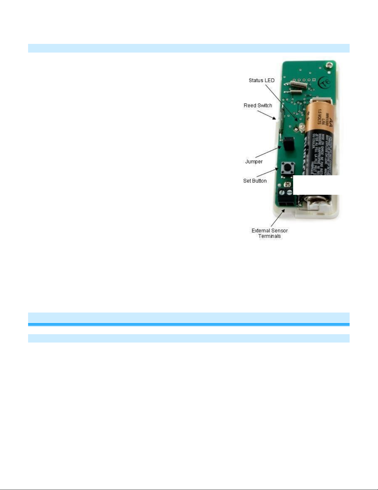
Open/Close Sensor Hardware
Reed Switch
Detects whether magnet is with in ½” of the main case:
• Closed state when magnet is within ½”
• Opened state when magnet is further than ½”
Jumper
When jumper is installed (default), Open/Close Sensor will send an
INSTEON “on” command when it opens and an “off” command when it
closes. W hen jumper is uninstalle d (as in Multi-Scene Mode), Open/Close
Sensor will activate scene 1 when it opens and activate scene 2 when it
closes.
NOTE: When installin g or uninstalling jumper, remove and replac e battery
for new jumper setting to take effect
Set Button
• Links other INSTEON devices (responders)
• Controls linked responders (scene 1): Tap to toggle between on
and off
External Sensor Terminals
When using an extern al se nsor, O pen/Clos e Sensor is in closed s tate when
either external s ensor terminals or reed switch are closed. In other words,
Open/Close Sensor opens when both external sensor ter minals and reed
switch are open. See Advanced External Sensor Use for more information.
Status LED
Indicates:
• Change in state (open or close)
• Linking/unlinking mode (blinks)
Arrows
Arrows indicate reed switch location inside main case, so magnet should be installed as close as to them as
possible.
Magnet
Included magnet is installed on o pposing plane than Open/Close Sensor main c ase. It should be less tha n ½” away
from the main case when door/window, etc. is closed and further than ½” when open.
shown for clarity)
Installation
Install Open/Close Sensor
1) Remove sensor (larger device) cover by prying up at “open”
2) Install included AA battery (don’t replace cover yet)
3) Peel backing off double-stick tape on back of sensor
4) Mount sensor:
• If installing on door, w ith white set button between door edge and battery, gently press sensor to door frame
approximately 3” from top of door (such that door slightly clears it when closing)
• If installing on window, with set button between window and battery, gently press to window frame (such that
window will slightly clears it when closing)
5) Press and hold sensor set button for 5 seconds until LED begins blinking
6) For US installations, press and hold nearest Range Extender (previously called Access Point) set button until it
beeps
a) If sensor LED continues blinking, sensor is not within range, move Range Extender to a closer outlet and
return to step 5
7) Peel backing off double-stick tape on back of magnet case
8) Mount magnet:
Page 3 of 9 2843-222/2843-422/2843-522 - Rev: 1/21/2014 7:18:39 AM
Page 4

Controller
Responder
Link
• If installing on door, mount magnet as near door edge as possible (within ½” of sensor horizontally) and with
one end of magnet aligned with set button and other end of magnet aligned with far end of sensor, gently
press on door
• If installing on window:
a) Open window and carefully replace sensor cover (open label on same side as battery)
b) Close window
c) Gently apply magnet to window as close to sensor as possible
d) Open window and carefully remove sensor cover
9) Test by opening and closing door or window
Sensor LED will blink once each time opened or closed
Otherwise, move sensor and magnet closer together when closed and test again
Connecting an External Sensor to Open/Close Sensor
NOTE: For basic use of Open/Close Sensor’s external sensor terminals, it is not recommended to also use
Open/Close Sensor’s internal reed switch to help ensure desired behavior. If connecting multiple sensors to
Open/Close Sensor’s external sensor terminals and/or using Open/Close Sensor’s reed switch in addition to an
external sensor, see Advanced External Sensor Use.
1) Use a small screwdriver to remove Open/C los e Sens o r main case cover
2) Strip sensor wire about ¼”
3) Unscrew external sensor terminals, connect sensor wire, and screw in terminals
4) Test by opening and closing sensor
Open/Close Sensor s tatus LED will blink once when sensor opens or closes
5) If you haven’t alre ady done so, link desired responders before replacing cover. See Make Open/Close Sensor a
Controller.
6) Replace Open/Close Sensor main case cover
INSTEON Setup
INSTEON Controller s, R es pon der s and Li nk s
Let’s define a few terms.
• The INSTEON “transmitter” is called a controller
• The INSTEON “receiver” is called a responder
Note: Some devices are controllers only (e.g., open/close and motion sensors, handheld remotes), some are
responders only (e.g., FanLinc), and some can be controllers and responders (e.g., switches and dimmers).
• The association between the controller and responder is called a link
Note that a link is one way. If you want control the other way (making the responder a controller), and the devices are
capable of it, simply add a link “the other way.”
Default Mode
In default mode, Open/Close Sensor will:
• Turn on responders when it opens
• Turn off responders when it closes
This mode is ideal for garage doors, closets, sheds, etc.
If you require more flexible functionality, see Using Open/C los e Sensor’s Multi -Scene Mode.
Page 4 of 9 2843-222/2843-422/2843-522 - Rev: 1/21/2014 7:18:39 AM
Page 5

Open/Close
Responder
Make Open/Close Sensor a Controller
Use Open/Close Sensor to control other INSTEON devic es:
1) If using default mode, ens ure Open/Close S ensor jumper is installed. If using multi-scene mode, jumper should
be uninstalled (or removed).
NOTE: When changing jumper setting, battery will need to be removed and then reinstalled for new jumper
setting to take effect.
2) Press and hold Open/Close Sensor set button for 3 seconds
Open/Close Sensor LED will start blinking green
3) Turn responder on (or any other state such as on 50% or even off)
4) Press and hold responder set button for 3 seconds
Open/Close Sensor LED will turn solid green
5) Test by opening and closing magnet/sensor
Responder load will respond appropriately
Sensor
(Controller)
Notes:
- To add multiple responders, repeat steps 2-4 or see Make Open/Close Sensor a Controller of Multiple
Responders
Make Open/Close Sensor a Controller of Multiple Responders
1) Press and hold Open/Close Sensor set button for 3 seconds
LED will start blinking green
2) Tap Open/Close Sensor set button
LED will start double-blinking green
3) For each responder you are adding:
a. Adjust responder to desired scene brightness/state
b. Press and hold set button for 3 seconds
4) Press and hold Open/Close Sensor set button for 3 seconds
LED will stop blinking
6) Test by opening and closing magnet/sensor
All responder loads will respond appropriately
Remove Open/Close Sensor as a Controller
If you no longer want Open/ Close Se ns or to control another device (or are removing Open/Close Sensor) it is
important that you follow the instructions below for each responder.
1) Press and hold Open/Close Sensor set button for 3 seconds
Open/Close Sensor LED w ill start bl ink ing gr een
2) Press and hold Open/Close Sensor set button again for 3 seconds
Open/Close Sensor LED will continue blinking green
3) Press and hold responder set button for 3 seconds
Open/Close Sensor LED will stop blinking and turn solid
4) Test by opening and closing magnet/sensor
Former responder will not respond
Open/Close Sensor status LED will continue blinki ng
NOTE: If you are using multi-scene mode, devices linked to scene 2 will not respond when Open/C lose Se ns or set
button is tapped
Using Open/C lose Sensor ’s Multi-Scene Mode
In multi-scene mode, Open/Close Sens or will:
• Activate scene 1 when it opens
• Activate scene 2 when it closes
This mode is ideal when you need more flexibility:
• For rooms where you want lights left on after door is clos ed – simply don’t link any respo nders to s cene 2 in
this case
• Turning lights on at full-bright when door is opened and dim when door is closed
• Activating t wo indep end ent s c enes when door/window is opened as opposed to closed
Page 5 of 9 2843-222/2843-422/2843-522 - Rev: 1/21/2014 7:18:39 AM
Page 6

Linking in Multi-Scene Mode
1) Open Open/Close Sensor cover and ensure jumper is uninstalled (or removed). When uninstalling jumper,
battery needs to be removed and then reinstalled for new jumper setting to take effect
2) Move Open/Close Sensor magnet away from main case, putting it in open state
If Open/Close Sensor w as c losed, LED will blink once
3) Link desired responders for when Open/Close Sensor opens (scene 1). See Make Open/Close Sensor a
Controller.
Scene 1 will activate when ever Open/Close Sens or is opened. The Set butto n toggle sending O N between
Scene 1 and Scene 2 when tapped (while O p en/C los e Sensor is opened).
4) Move Open/Close Sensor magnet close to main case, putting it in closed state
Open/Close Sensor status LED will blink once
5) Link desired responders for when Open/Close Sensor opens (scene 2)
Scene 2 will activate whenever Open/Close Sensor is closed. The Set button toggle sending ON between
Scene 1 and Scene 2 when tapped (while Open/Close Sensor is opened).
6) Test that responders are working as expected by opening and closing your door or window
Scene 1 will activate when door or window is opened and sc ene 2 will activate when closed
Unlinking in Multi-Scene Mode
1) Open Open/Close Sensor cover and ensure jumper is uninstalled (or removed)
2) Move Open/Close Sensor magnet away from main case, putting it in open state
If Open/Close Sensor w as c losed, LED will blink once
3) Unlink desired responders from scene 1. See Unlinking an INSTEON Responder from Open/Close Sensor.
Responders will no longer respond when Open/Close Sensor is opened or set button is tapped
4) Move Open/Close Sensor magnet close to main case, putting it in closed state
Open/Close Sensor status LED will blink once
5) Unlink desired responders from scene 2
Responders will no longer respond when Open/Close Sensor is closed or set button is tapped
6) Test by opening and closing your door or window
Responders will no longer respond when Open/Close Sensor is opened or closed
Scenes
Devices in a scene can each ha ve different s ettings. This prov ides for advance d lighting, aud io, etc scene creation.
Software is recommended for scene management.
INSTEON scenes are very easy to set up – just link more than one responder to the same controller. Then, all
INSTEON devices linked in the scene will respond as a group.
Advanced Features
Advanced External Sensor Use
For advanced users, a single Open/Close Se ns or can be used to:
• Monitor several doors/windows
• Monitor several different types of sensors
• Monitor external sensors in addition to its internal reed switch
Using Several Sensors
When several sensors (eve n of diff erent t ypes) are c onnect ed to Open/C lose S ens or external sensor term inals, k eep
in mind that Open/Close S ensor only has t wo states: opened a nd closed. So if you have several s ensors connect ed
in the following conf igurations, note O pen/Close S ensor behavior (it is ass umed in this exam ple Open/Close Sens or
internal reed switch is not being used).
• Several sensors connected in series – Open/Close Sensor will show open if any sensors are open and
closed when all sensors are closed
• Several sensors co nnected in parallel – Open/Close Sensor will sho w open when all sensors are open and
closed if any sensors are closed
NOTE: If magnetic door/window contacts are used, there are two types:
Page 6 of 9 2843-222/2843-422/2843-522 - Rev: 1/21/2014 7:18:39 AM
Page 7

• Normally open – when door /win do w is closed, sensor wil l sho w open. When door/window is op en, s ensor will
show closed
• Normally closed – when door/window is clos ed, senso r will show closed. When door/ window is open, s ensor
will show open
Using Internal Reed Switch and External Sensors
When Open/Close Sensor external sensors input is used in conjunction with its internal reed switch, Open/Close
Sensor behaves much like several sensors connected in parallel (above), meaning:
• Open/Close Sensor will be open when both internal reed sw itch and external reed switch sensor terminals
show open
• Open/Close Sensor wi ll be closed when either internal reed switch or external sensor terminals show closed
Power Restore
Open/Close Sensor stores all of its settings, such as links to other INSTEON devices, with non-volatile memory.
Because settings are saved in non-volatile memory, they will not be lost when the battery is removed.
Factory Reset
All settings and scenes will be erased and return to factory default settings.
1) If you are using Open/Close Sensor to control any responders, unlink them from Open/Close Sensor. See
Remove Open/Close Sensor as a Controller.
2) Use a small screwdriver to gently remove Open/Close Sensor main case
3) Remove battery and wait at least 15 seconds
4) Press and hold set button on Open/Close Sensor while reinstalling battery
5) Release set button when the status LED turns on
Open/Close Sensor status LED will stay on for about 4 seconds and then turn off
Specifications
General
Product name INSTEON Open/Close Sensor (formerly #2421, TriggerLinc)
Brand/manufacturer INSTEON
US 2843-222 (formerly #2421)
Manufacturer product number
UPC
Warranty 2 years, limited
Operation
Status LED Green. Blinks on activation
Operational Gap: 1/2" between magnet and main case
Sense Modes:
EU 2843-422
AUS/NZ 2843-522
US 718122388912
EU 813922013009
AUS/NZ
Jumper Installed: Open = Group 1 On, Closed = Group 1 Off
Jumper Uninstalled: Open = Group 1 On (or off), Closed = Group 2 On (or
Off)
813922013016
Aux. Sensor Input: Senses contact closure
Aux. Sensor Input Wire: >= 20 gauge wire
Setup Memory: Non-volatile EEPROM
INSTEON
Page 7 of 9 2843-222/2843-422/2843-522 - Rev: 1/21/2014 7:18:39 AM
Page 8

EU
869 MHz
AUS/NZ
921 MHz
INSTEON Addresses 1 hard-coded out of 16,777,216 pos sib le
INSTEON controller Yes
INSTEON responder No
Maximum links/scenes 30
Software configurable Yes
RF range
Up to 150 feet (50 meters) open air*
*Range may vary due to local interference
INSTEON device category 0x10 (all frequencies)
0x02
0x06
0x07
INSTEON device subcategory
US
EU
AUS/NZ
Mechanical
Case color White
Set button Yes
Dimensions
Main Case: 3.46" x 1.32" x 0.76" (88mm x 34mm x 19mm)
Magnet: 2.28" x 0.55" x 0.43" (58mm x 14mm x 11mm)
Weight 3.5 oz (99g)
Operating environment Indoors
Operating temperature range 32° to 104° F (0° to 40° C)
Operating humidity range 0-85% relative humidity
Storage temperature range -4° o to 158° F (-20° to 70° C)
Electrical
US 915 MHz
RF Frequency
Power: 1 AA Alkaline Battery (included)
Battery Life: 6 months (w/ 2 links @ 50 activations per day)
Certification: FCC & Industry Canada
X10
X10 Support N/A
Certification and Warranty
FCC and Industry Canada Compliance Statement
This device complies with FCC Rules Part 15 and Industry Canada RSS-210 (Rev. 7). Operation is subject to the following two conditions:
(1) This device may not cause harmful interference, and
(2) This device must accept any interference, including interference that may cause undesired operation of the device.
Le present appareil est conforme aux CNR d' Industrie Canada applicabl es aux appareils radio exem pts de licence. L'exploitati on est autorise aux deux condi tions
suivantes:
(1) l'appareil ne doit pas produire de brouillage, et
(2) l'utilisateur de l'appareil doit accepter tout brouillage radiolectrique subi, mme si le brouillage est susceptible d'en compromettre le fonctionnement.
The digital circ uitry of t his devi ce has been t ested and fou nd to com ply wi th the li mits fo r a Cla ss B digi tal dev ice, p ursuan t to Part 15 of the FCC Rules. T hese l imits
are designed to prov id e r easonable protect io n a gainst harmful inte rfe re nc e i n r esi de nti al installations. Thi s eq uipm ent generates, uses, and can radi ate ra dio f re que nc y
energy and, if n ot installed and used i n accordance with the in structions, may cause h armful interference to r adio and television recept ion. However, there is no
guarantee that inte rfere nce will not occ ur in a p artic ular ins talla tion . If thi s devi ce d oes caus e s uch inte rfe rence, whic h can be verifi ed b y turnin g the d evice off a nd on,
the user is encouraged to eliminate the interference by one or more of the following measures:
- Re-orient or relocate the receiving antenna of the device experiencing the interference
- Increase the distance between this device and the receiver
- Connect the device to an AC outlet on a circuit different from the one that supplies power to the receiver
- Consult the dealer or an experienced radio/TV technician
Page 8 of 9 2843-222/2843-422/2843-522 - Rev: 1/21/2014 7:18:39 AM
Page 9

WARNING: Change s or modifications to this dev ice not expressly app roved by the party respon sible for compliance coul d void the user’s authorit y to operate the
equipment.
Declaration of Conformity
Hereby, INSTEON declares that this device is in compliance with the essential requirements and other relevant provisions of the following Directives:
1) Electromagnetic Compatibility Directive 2004/108/EC
2) Hazardous Substance Directive 2005/95/EC
Technical data and copies of the original Declaration of Conformity are available and can be obtained from INSTEON; 16542 Millikan Ave, Irvine, CA, USA.
User Information for Consumer Products Covered by EU Directive 2002/96/EC on Waste Electric and Electronic Equipment (WEEE)
This document contains important information for users with regards to the proper disposal and recycling of INSTEON products. Consumers are required to comply
with this notice for all electronic products bearing the following symbol:
Environmental Information for Customers in the European Union
European Directive 2002/96/EC requires that the equipment bearing this symbol on the product and/or its packaging must not be disposed of with unsorted municipal
waste. The symbol indicates that this product should be disposed of separately from regular household waste streams.
It is your responsibility to dispose of this and other electric and electronic equipment via designated collection facilities appointed by the government or local authorities.
Correct disposal and recycling will help prevent potential negative consequences to the environment and human health.
For more detailed information about the disposal of your old equipment, please contact your local authorities, waste disposal service, or the shop where you purchased
the product.
DECLARATION OF CONFORMITY TO R&TTE DIRECTIVE 1999/5/EC for the European Community, Switzerland, Norway, Iceland and Liechtenstein
Product category: general consumer (category 3).
English: This equipment is in compliance with the essential requirements and other relevant provisions of the European R&TTE Directive 1999/ 5/E C
Deutsch [German]: Dieses Gerät entspricht den grundlegenden Anforderungen und de n weit er en en ts p rec he nde n Vo rga be n der R ichtl i ni e 19 99/ 5/E U.
Nederlands [Dutch]: Dit apparaat voldoet aan de essentiele eisen en andere van toepassing zijnde bepalingen van de Richtlijn 1999/5/EC.
Svenska [Swedish]: Denna utrustning står I överensstämmelse med de väsentliga egenskapskrav och övriga relevanta bestämmelser som framgår av direktiv
1999/5/EG.
Français [French]: Cet appareil est conforme aux exigences essentielles et aux autres dispositions pertinentes de la Directive 1999/5/EC
Español [Spanish]: Este equipo cumple con los requisitos esenciales asi como con otras disposiciones de la Directiva 1999/5/CE.
Português [Portuguese]: Este equipamento está em conformidade com os requisitos essenciais e outras provisões relevantes da Directiva 1999/5/EC.
Italiano [Italian]: Questo apparato é conforme ai requisiti essenziali ed agli altri principi sanciti dalla Direttiva 1999/5/CE.
Norsk [Norwegian]: Dette utstyret er i samsvar med de grunnleggende krav og andre relevante bestemmelser i EU-direktiv 1999/5/EF.
Suomi [Finnish]:Tämä laite tÿttää direktiivin 1999/5/EY olennaiset vaatimukset ja on siinä asetettujen muiden laitetta koskevien määräysten mukainen.
Dansk [Danish]: Dette udstyr er i overensstemmelse med de væsentlige krav og andre relevante bestemmelser i Direktiv 1999/5/EF.
Polski [Polish]: Urządzenie jest zgodne z ogólnymi wymaganiami oraz szczególnymi warunkami okreslonymi Dyrektywą UE: 1999/5/EC
Limited Warranty
Seller warrants to the ori ginal consumer purch aser of this product that, f or a period of two years from the date of purchase, this p roduct will be free fro m defects in
material and work m anship and will perf orm in s ubs t antial conformit y to th e description of th e p roduct in this Ow ner’ s Man ual. This warranty shall not appl y t o de fects or
errors caused by misuse or neglect. If the pr od uct i s fou nd t o be defective in materi al or workmanship, or if the pr odu ct does not perform as w ar ra nte d ab ove during the
warranty period, Sel ler will ei ther r epair it, replac e it, or refu nd th e purcha se price, at its opti on, upo n receipt of the pr oduc t at the add ress bel ow, post ag e prepai d, with
proof of the date of pur chase a nd an explan ation of t he defec t or erro r. The repai r, repla cement, or refun d that is p rovided for a bove shall be the ful l extent of Seller’s
liability with respect to this product. Fo r rep air or r eplacement during the warranty peri od, c all INST EO N a t 866-243-8022 with the Model # an d R evi s ion # of t he d evice
to receive an RMA# and send the product, along with all other required materials to:
INSTEON
ATTN: Receiving
16542 Millikan Ave.
Irvine, CA 92606-5027
Limitations
The above warranty is in l ie u of and Seller disclaim s all othe r warra nti e s, wh et her o ral or written, express o r i m pli ed, i ncl udi ng a n y warr ant y o r m erc han ta bi lity or fitness
for a particular pu rpose . An y im plie d warr ant y, includi ng any war rant y of m erchan tabili ty o r fitness for a partic ula r pur pose, which m ay not be di sclaim ed or sup planted
as provided above shall be limi ted to the two-year of the express w arrant y above. No oth er repres entatio n or claim of an y nature b y any person s hall be bi nding upo n
Seller or modify the terms of the above warranty and disclaimer.
Home automatio n devices have t he risk of failure to operate, in correct operati on, or electrical or mechanical tam pering. For optim al use, manu ally verify the device
state. Any home automation device should be viewed as a convenience, but not as a sole method for controlling your home.
In no event shall Seller b e liable for special, i ncidental, consequ ential, or other dam ages resulting from possession or use of thi s device, includin g without limitation
damage to prope rty an d, to the exten t perm itt ed b y law, perso nal i njur y, ev en if Sel ler k new or s hould hav e kno wn of th e pos sibil ity of s uch dam ages. S om e states do
not allow limitations on how long an implied warranty l asts and/or the e xcl usi o n o r li m itation of damages, in which cas e t he ab ove l im i t ations and/or excl usio ns m a y not
apply to you. You may also have other legal rights that may vary from state to state.
Protected under US and foreign patents (see www.insteon.com/patents)
© Copyright 2013 INSTEON, 16542 Millikan Ave., Irvine, CA 92606, 866-243-8022, www.insteon.com
Page 9 of 9 2843-222/2843-422/2843-522 - Rev: 1/21/2014 7:18:39 AM
 Loading...