

Page 1
8
JUS
A
A
Indoor/Outdoor
INSTEON™ Motion Sensor Model #2842-2
The INSTEON Motion Sensor is an indoor/outdoor motion sensor that will
turn INSTEON controlled lights on and off in response to movement around
your home. The sensor also contains a photocell, allowing you to configure
the unit to operate your lights only at night. Pair the Motion Sensor with
INSTEON software for almost limitless device automation possibilities.
In this package you will find the Motion Sensor, a 9V battery, a swivel
mount and two screws.
1. INTRODUCTION
Motion Sensor
WHEN MOTION IS SENSED
1. When motion is sensed the Motion Sensor will send an ON command
to up to 30 linked INSTEON responders and flash its LED (unless it is
daytime and unit is in night-only mode).
2. Sensor will begin its automatic countdown.
3. Whenever motion is sensed during countdown, the countdown will be
reset to easily allow you to create “occupied” versus “unoccupied”
modes for your home.
4. When countdown expires the Sensor will send an OFF command to
all linked responders (unless it is in ON-only mode).
APPLICATIONS
1. Turn on driveway or front step lights when visitors approach.
2. Have your fountain always on when you are around (and off when
you are away).
3. Save money by having HVAC and lighting automatically go into
energy savings mode when no one is around.
INSERT BATTERY
Use a small Phillips head screwdriver to remove screw and cover from
battery compartment on back of unit. Attach the included 9-volt battery. Do
not replace compartment cover until instructed to do so later in this guide.
Wait 5 minutes for the circuit to stabilize. To confirm unit is functioning, tap
the Set button a couple of times while watching the front of the unit. Each
time you tap the Set button, a red LED behind the sensor lens will flash.
Don’t worry if the LED flashes when you are not tapping the Set button; it is
simply indicating that motion is being detected.
(Close-up
of battery
compartment)
ACCESS POINTS
Motion Sensor requires at least one INSTEON Access Point (#2443) or
other dual-band product installed in your home. To confirm the Motion
Sensor is within RF range of your Access Point, have a friend watch the
LED on the side of your Access Point while you tap the Set button on the
Sensor (while holding it where you plan to install it). Access Point’s LED will
flash a couple times every time you tap the Set button if it is within range.
Set
button
9V
Battery
2. OPERATION
3. SETUP
Swivel
Mount
2- 3x18
Screws
4. SETUP INSTEON DEVICE CONTROL
LINKING TO INSTEON RESPONDERS
1. Press and hold the Set button on Motion Sensor for 5 seconds (until red
LED behind sensor lens begins blinking steadily.) You now have 4
minutes to complete step 2)
2. Press and hold the Set button
responder you would like the Motion Sensor to control (its LED may
blink).
3. The Motion Sensor LED will stop blinking (if not, try step 2 again).
4. Test by tapping the Set button on Motion Sensor. Each tap should
toggle the device you linked on and off. (The Motion Sensor LED will
flash each time the Set button is tapped.)
5. Repeat this procedure for up to 32 responders.
1
For multi-button responders (e.g., KeypadLinc™), tap the button you wish
to control before pressing and holding its Set button.
1
for 5 seconds on the INSTEON
5. DETECTING ARE
6. LOCATION TIPS
BEST LOCATIONS
Select a detector location that will provide the required coverage. Keep the
following potential problems in mind:
1. Reflective surfaces
such as mirrors or windows. This may distort the coverage pattern or
reflect sunlight directly onto the detector.
2. Air flow
3. Moisture
4. Sunlight - Do not aim the detector where it will receive direct or
5. Obstruction
6. Pet rejection
7. Fireplace
8. Snow/ice
9. Dirt
- Avoid locations that are subject to direct high air flow, such
as near an air duct outlet.
- Do not place the detector near sources of steam or oil.
reflected (mirror) sunlight.
plants or filing cabinets) that will limit or block sensor coverage.
has access. Do not place furniture or objects higher than what a pet
can climb onto (about 3 ft/0.9 m) or closer than 6 ft/1.8 m away from
the detector.
- Do not place the detector near afireplace as the light and
heat may interfere with Motion Sensor’s detection ability.
– Snow or ice on the Fresnel lens may interfere with
Motion Sensor’s detection ability.
– Dirt on the Fresnel lens may interfere with Motion Sensor’s
detection ability.
- Do not aim the detector at reflective surfaces
- Do not place the detector near large objects (such as
- Do not aim the detector at a stairway to which a pet
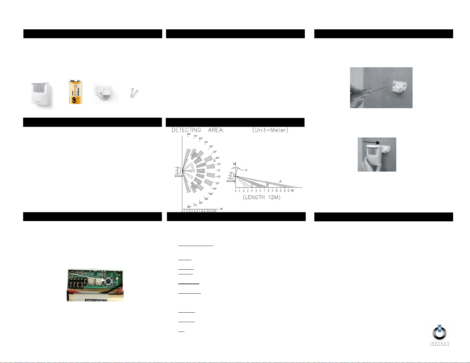
7. MOUNT SENSOR
MOUNTING (See Location Tips for help)
1. Use the two small screws (included) to secure the swivel mounting
bracket at your desired location.
2. Slide Motion Sensor onto the swivel mounting bracket (sliding to the
right) until you hear a click.
3. Aim Motion Sensor towards the area in which you wish to detect motion
(detection area).
4. Test by walking through the area. Linked responders should turn ON
when motion is sensed and OFF one minute after last motion sensed.
. AD
AIMING AND SENSITIVITY
1. Tap the Set button on Motion Sensor until the linked respond er(s) turn
OFF.
2. Within 10 seconds, walk far out of detection area.
3. Wait 20 seconds.
4. Walk into and near your detection area. Your linked responders will
turn ON (LED will flash upon initial motion, then once every 8 seconds
during motion).
a. If LED does not flash while you are moving within the
desired detection area, readjust Sensor (usually means
pointing the Sensor upward)
b. If LED flashes while you’re moving outside detection area
i. Readjust Sensor to decrease range (usually means
ii. If aiming sensor does not generate desired results
T DETECTION ARE
aiming the Sensor downward)
place jumper 1 on both pins (see SETUP MODES
section).
Page 2
G
CC
and IC
©
f
JUS
9. SETU
j
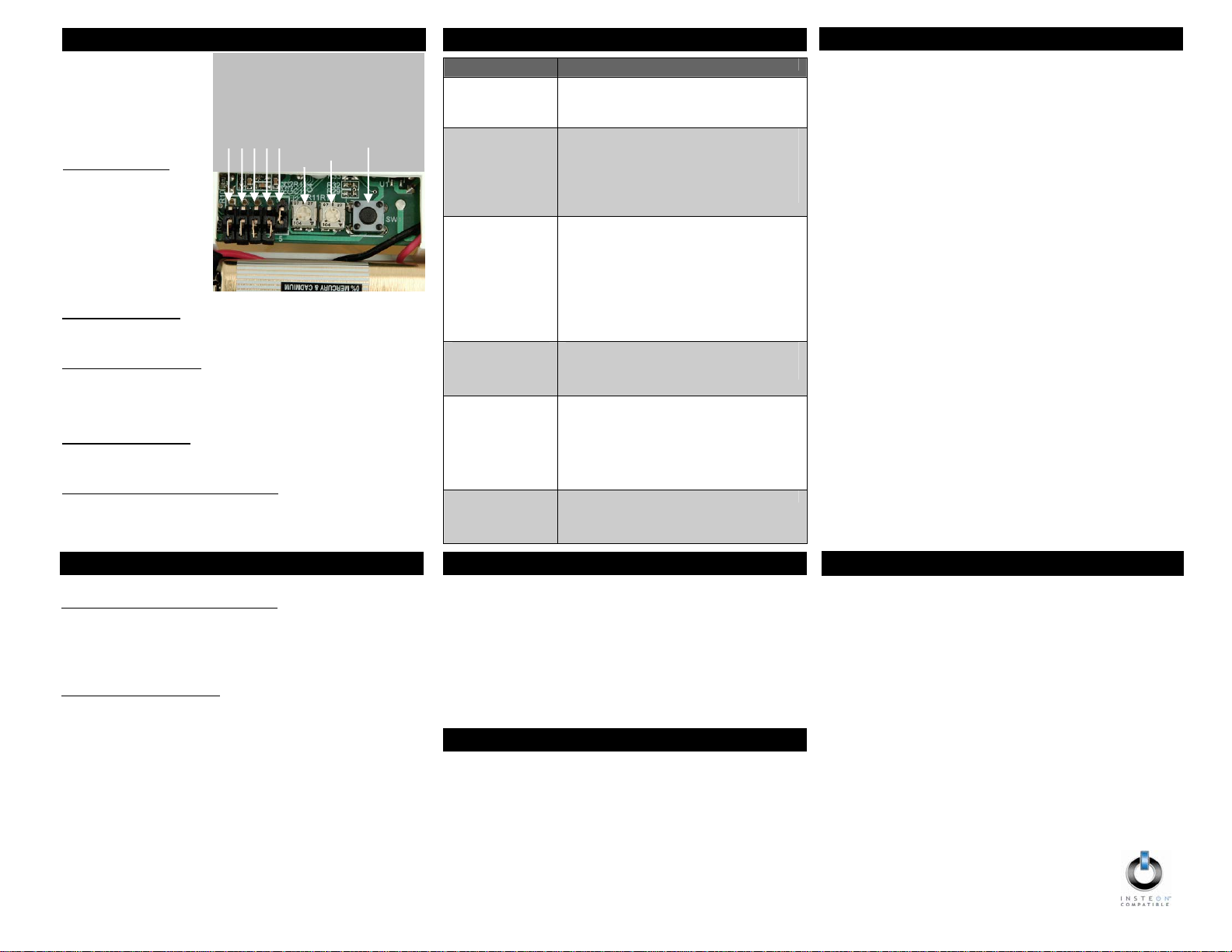
SET JUMPERS
Jumpers are small plastic
“boxes” that act as a switch.
When installed on two pins,
the switch is “on.” When
installed on one pin (or
missing), the switch is “off”.
Jumper 1 – Sensitivity
To reduce Sensor’s
detection range (by
approximately 33%),
carefully remove jumper 1
(the left-most jumper) from
the single pin on which it is
installed using a pair of
needle-nose pliers. Reinstall
it on both pins. Tap the Set
button once, wait 10
and activate motion to establish the new setting.
seconds
Jumper 2 – Disable LED
.
If you wish to disable the LED (it will still operate during setup), install
umper 2 on both pins. Tap the Set button once, wait 10 seconds and
activate motion to establish the new setting.
Jumper 3 – Night-Only Mode
If you wish to have the Sensor operate only when dark, install jumper 3 on
both pins. Tap the Set button once, wait 10 seconds and activate motion
to establish the new setting. Note: it takes 3.5 minutes (or seven Set
button taps) to detect the difference between day and night. (See
Day/Night Threshold in ADJUST MODES below for details.)
Jumper 4 – On-Only Mode
If you wish to disable the automatic “Off” countdown, install jumper 4 on
both pins and the Motion Sensor will only send “On.” Tap the Set button
once, wait 10 seconds and activate motion to establish the new setting.
Jumper 5 – Remote (Software) Management
If you wish to manage all of Motion Sensor’s se ttings via INSTEON
software (such as HouseLinc 2), install jumper 5 on both pins. Then, press
and hold the Set button on Motion Sensor to put the unit in linking mode
and allow the INSTEON software to access its settings.
ADJUST DIALS
Left Dial – Adjust Automatic “Off” Countdown
Using a small Phillips screwdriver, adjust the time duration that Motion
Sensor will wait to send an OFF command after the last motion sensed.
Turning the dial all the way counterclockwise sets the countdown to 30
seconds; turning it all the way clockwise sets it to 2 hours. Anywhere in
between results in a proportional difference between 30 seconds and 2
hours.
Right Dial – Day/Night Threshold
Using a small Phillips screwdriver, adjust the day/night threshold to
desired light level: turning the dial clockwise increases the light level, and
counterclockwise decreases the light level. For example, turning the dial
all the way to the right clockwise will make Motion Sensor read “night” no
matter how bright it is. Likewise, turning the dial all the way to the left
counterclockwise will make Motion Sensor read “day” no matter how dark
it is. Turning the dial anywhere in between will adjust the specific light
level Motion Sensor uses to determine “night” and “day.” To test, set
Motion Sensor to Night-Only mode (see jumper 3 above) and tap the Set
button seven times. If it reads the current light level as “Night,” it will turn
on its linked responders on first sensed motion. If it reads “Day,” the LED
will flash on first motion, but it will not turn on its linked responders.
P MODES (OPTIONAL)
10. AD
Jumper 1
Jumper 2
Jumper 3
T MODES
Jumper 4
Jumper 5
Automatic Off Countdown
Day/Night Threshold
Set button
11. TROUBLESHOOTIN
Symptom Resolution
Sensor won’t link to
responders
Sensor won’t
control linked
responders
LED flashing rapidly
after motion is
detected
LED not flashing
upon motion
Not sensing motion a) Light detected and unit is in night-only mode.
LED is doubleflashing upon
motion
Move a dual-band INSTEON device (e.g.,
Access Point) closer to the Motion Sensor.
a) Make sure LED flashes to confirm it has
power and is sensing motion.
b) Sensor is in night-only mode (and it is “day”).
c) Move a dual-band INSTEON device (e.g.,
Access Point) closer to the Motion Sensor.
d) Sensor is in its one-minute “off” countdown.
Sensor did not receive an acknowledgement
from one or more linked devices. If this occurs
repeatedly you may need to move a dual-band
INSTEON device closer to the Sensor or you
may need to unlink a device which is no longer
in use in your home. If the INSTEON
responders are no longer available, you may
either use a software application or perform a
factory reset to remove the unwanted links.
a) You may need to wait up to 8 seconds to
see the flash.
b) Battery may need to be replaced.
b) Motion Sensor aimed too low.
c) Temperature too high or low (sensor needs
to be able to distinguish between what is
being sensed and its surroundings).
d) See LOCATION TIPS section.
Low battery warning: replace with fresh battery.
12. REMOVE CONTROL OF INSTEON
UNLINKING FROM INSTEON RESPONDERS
1. Press and hold the Set button on Motion Sensor for 5 seconds (until
red LED behind sensor lens begins blinking) and release.
2. Press and hold the Set button on Motion Sensor for an another 5
seconds (until the LED changes its blink pattern to a slow blink
where it is on longer than off).
3. Press and hold the Set button on the INSTEON Responder you
would like to unlink (until its LED blinks).
4. The Motion Sensor LED will stop blinking (if not, repeat step 3).
5. Test by tapping the Set button on Motion Sensor. Taps should no
longer control the unlinked device.
13. FACTORY RESET
RETURN UNIT TO FACTORY SETTINGS
1. If possible, unlink from all Responders before proceeding.
2. Remove battery.
3. Wait 15 seconds.
4. While pressing and holding the Set button, reinstall the battery. Do
not let go of the Set button.
5. Motion Sensor will emit a long beep. Continue pressing and holding
the Set button until beep stops, then release.
14. F
This device complies with FCC Rules Part 15 and Industry Canada RSS210 (Rev. 8). Operation is subject to the following two conditions:
(1) This device may not cause harmful interference, and
(2) This device must accept any interference, including interference
that may cause undesired operation of the device.
Le present appareil est conforme aux CNR d'Industrie Canada applicables
aux appareils radio exempts de licence. L'exploitation est autorise aux
deux conditions suivantes:
(1) l'appareil ne doit pas produire de brouillage, et
(2) l'utilisateur de l'appareil doit accepter tout brouillage
radiolectrique subi, mme si le brouillage est susceptible d'en
compromettre le fonctionnement.
The digital circuitry of this device has been tested and found to comply with
the limits for a Class B digital device, pursuant to Part 15 of the FCC
Rules. These limits are designed to provide reasonable protection against
harmful interference in residential installations. This equipment generates,
uses, and can radiate radio frequency energy and, if not installed and used
in accordance with the instructions, may cause harmful interference to
radio and television reception. However, there is no guarantee that
interference will not occur in a particular installation. If this device does
cause such interference, which can be verified by turning the device of
and on, the user is encouraged to eliminate the interference by one or
more of the following measures:
- Re-orient or relocate the receiving antenna of the device
experiencing the interference
- Increase the distance between this device and the receiver
- Connect the device to an AC outlet on a circuit different from
the one that supplies power to the receiver
- Consult the dealer or an experienced radio/TV technician
WARNING: Changes or modifications to this device not expressly
approved by the party responsible for compliance could void the user’s
authority to operate the equipment.
TECHNICAL SUPPORT
Skylink has contracted with INSTEON for Motion Sensor support.
Customers should contact INSTEON for technical support.
1. www.smarthome.com (product page, help desk, wiki, live chat).
2. Email at support@smarthome.com.
3. Call the INSTEON Gold Line at1-800-SMARTHOME (800-762-7846).
Search for dual-band INSTEON products:
http://www.smarthome.com/dualband
P/N. 2842-2 Rev. 03-13-2012
2012 SKYLINK GROUP
 Loading...