

Page 1
INSTEON® Thermostat
Owner’s Manual (#2441TH, 2732-422, 2732-522)
Page 1 of 28 Rev: 1/21/2014 8:35 AM
Page 2

About INSTEON Thermostat 3
INSTEON Thermostat – Features and Benefits 3
What’s in the Box? 3
INSTEON Thermostat Button Overview 4
INSTEON Thermostat Operation an d Programming 5
Mode Button Operation 5
Energy Button Operation 6
Set Button Operation 7
Time/Sensor Button Operations 7
Program Button Operation 8
Fan and Hold Button Operations 10
Master Button Operation 10
Installation 11
Tools Needed 11
Installation 11
Wire Connections 12
Test Operation 13
Adding an INSTEON Wireless Thermostat 13
INSTEON Programming 14
Add INSTEON Thermostat as an INSTEON Controller 14
Removing INSTEON Thermostat as an INSTEON Controller 16
Add INSTEON Thermostat as an INSTEON Responder 17
Remove INSTEON Thermostat as an INSTEON Responder 17
User Setup Mode Overview 19
User Setup Mode 19
Temperature and Humidity Calibration Mode 21
Advanced 2-Stage Heating or Cooling Systems 22
Factory Reset 22
Specifications 23
Troubleshooting 25
DECLARATION OF CONFORMITY 26
Certification and Warranty 28
Limited Warranty 28
Limitations 28
Page 2 of 28 Rev: 1/21/2014 8:35 AM
Page 3

About INSTEON Thermos t a t
INSTEON Thermostat is a 7-day programmable INSTEON-compatible thermostat. INSTEON Thermostat
includes a humidity sensor and 2-stage heating plus 2-stage cooling capabilities.
Expand the system by creating extra temperature zones in your home. Simply add one or more INSTEON
Wireless Thermostats as accessories to your system. Additionally, a Waterproof Temperature Sensor can
be added and extended up to 100 feet for remote temperature sensing.
INSTEON Thermostat – Features and Benefits
• Installs and joins scenes with other INSTEON devices in minutes
• Saves energy and money by remotely controlling and automating your home’s heating and AC
• Communicates wirelessly over radio frequency (RF)
• Can automatically remotely control INSTEON devic es when INSTEON Thermostat reaches a
specified temperature or humidity level or switches to A/C or heat
• Reports changes in thermostat modes, temperature, humidity, setpoints and fan to compatible
automation controllers or software
• Fine-tunes thermostat setpoints by single degrees from any INSTEON controller with specific Up
and Down buttons
• Stores setup state in memory so settings aren’t lost during power outages
• Two-year warranty
• Controllable via the web and smartphone app (iOS/Android) using SmartLinc
INSTEON Hub
TM
controller or
What’s in the Box?
• INSTEON Thermostat
• Two mounting screws
• Two anchors
• Quick Start Guide
• Wire ID label stickers
Page 3 of 28 Rev: 1/21/2014 8:35 AM
Page 4
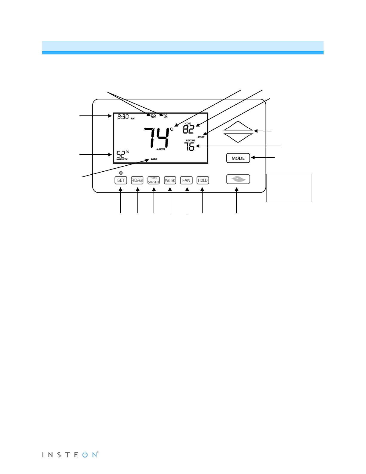
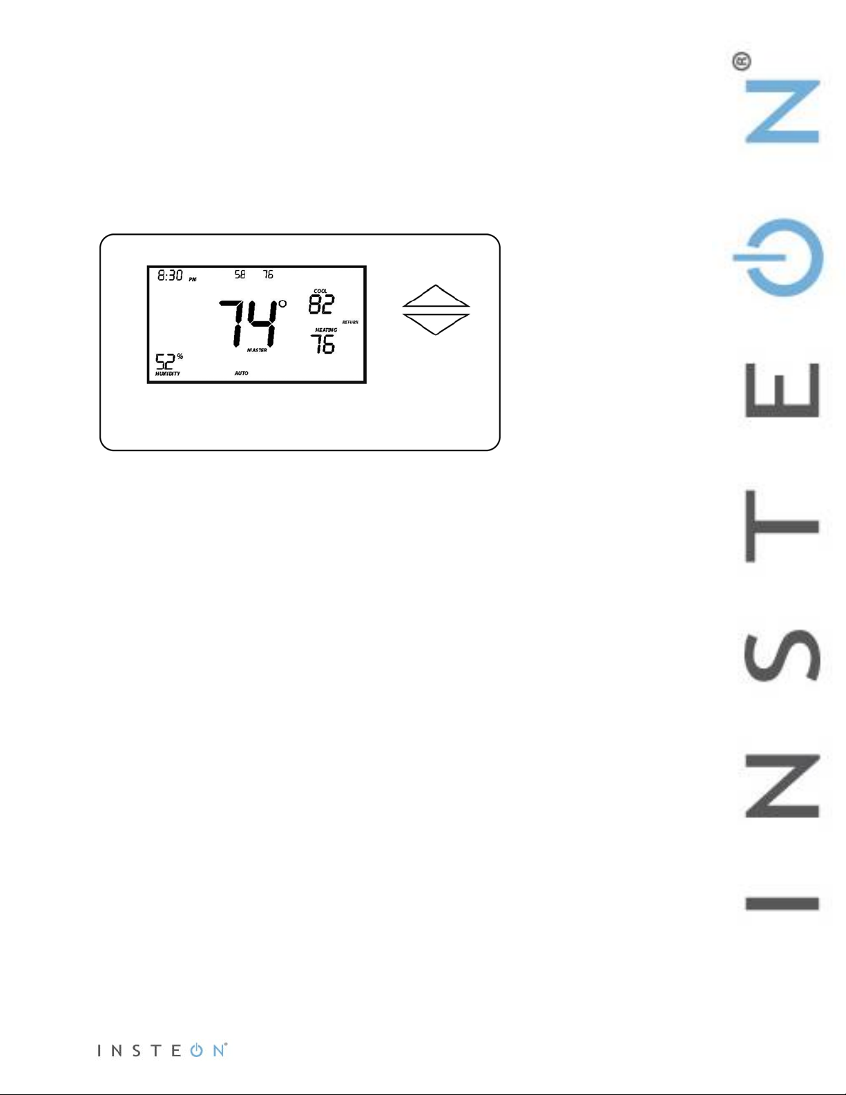
INSTEON Thermostat Sample
The gray buttons
Cool setpoint
Heat setpoint
Time of day
Humidity level
Time
Current
Temperature of remote
Current
Heat or Cool
INSTEON Thermostat Button Overview
2 1 4 5 6 7 8 9 3
sensors or zone thermostats
position 1 and position 2
(up to 2)
thermostat
mode:
Off, Auto,
temperature
state
are under the
INSTEON
Thermostat door
1) Up/Down buttons adjust the temperature setpoint based on the current mode.
2) Mode allows the user to select the current operational mode of the HVAC system. It cycles
among Off, Heat, Cool, Auto and Time of Day.
3) Energy (Leaf) button is designed as a quick access option that saves energy (and money). When
pressed, it will set back the setpoint by a specified value. The default value is 4° from the current
setting. To change the default offset value you must use software such as HouseLinc
4) Hold overrides a preprogrammed mode to stay in the current settings mode.
5) Fan cycles between Auto and Always On – there is no ind icat or for Auto Fan.
6) Master makes this device the master temperature controller when you have one or more zone
thermostats. Pressing and holding “Master” does not alter any scene or screen settings; it just
defines this INSTEON Thermostat as the master temperature controller.
7) Time/Sensor allows you to set the day and time. It cycles among hour, minute, day and time
programming.
8) Program allows you to set up the various preprogrammed modes (Wake, Leave, Return and
Sleep). It also allows you to setup various features and calibrate the temperature and humidity.
9) Set is for adding and removing INSTEON Thermostat to and from INSTEON scenes. It functions
like the Set button on other INSTEON devices.
TM
.
Page 4 of 28 Rev: 1/21/2014 8:35 AM
Page 5

INSTEON Thermostat O per ati on a nd Pr ogramming
Off Mode:
Heat Mode:
Cool Mode:
Auto Mode:
Time of Day Mode:
Mode Button Operation
• No setpoints are shown.
• Up/Down arrows do not do anything.
• Only Cool setpoint is shown.
• Up/Down arrows change Cool setpoint.
• The program mode is active as indicated by
the return annotation.
• The Time of Day annotation is not
displayed in the other four modes (Off,
Heat, Cool or Auto).
• Both Cool and Heat setpoints are shown.
• Up/Down arrows increase or decrease
values by the same amount.
• When the thermostat moves to the next
time period, the setpoints will be adjusted
accordingly.
• Only Heat setpoint is shown.
• Up/Down arrows change Heat setpoint.
• Both Cool and Heat setpoints are
shown.
• Up/Down arrows increase or decrease
values by the same amount.
Note:
Page 5 of 28 Rev: 1/21/2014 8:35 AM
• To adjust the gap bet ween t he setpoints in Auto mode, press Mode to select Heat and set the
temperature you desire. Press Mode to select Cool and set the temperature you desire.
Press Mode to return to Auto; the settings will reflect your changes.
• If you set Heat and Cool to the same temperature, Heat will automatically move down 2° (the
minimum allowable gap).
Page 6
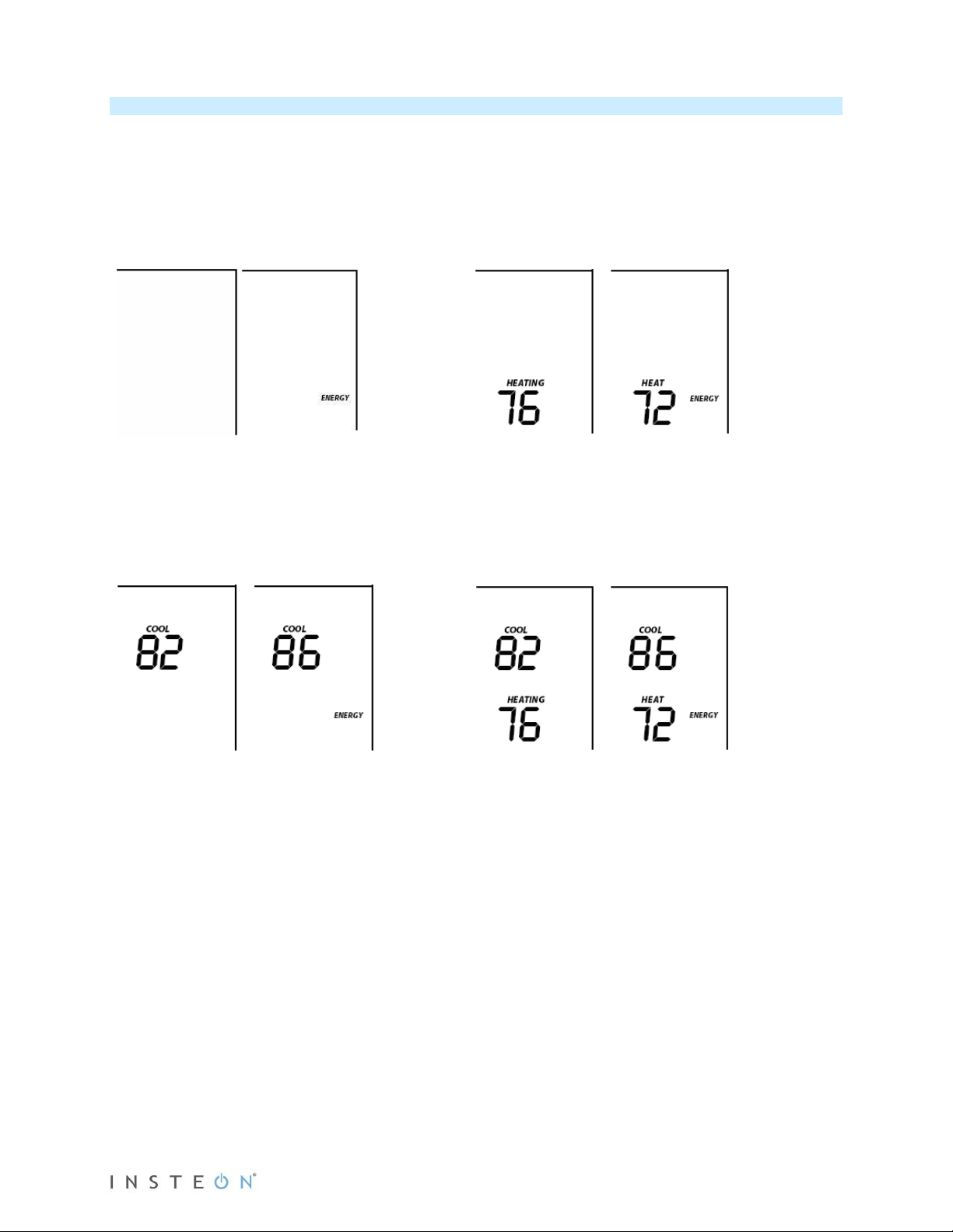
Energy Button Operation
From Off Mode:
is engaged.
From Heat Mode:
element reads “Heat.”
From Cool Mode:
From Auto Mode:
The Energy button is designed to be a quick, efficient energy-saving option. When you press the Energy
(leaf) button, INSTEON Thermostat will adjust the Heat and Cool setpoints by a specified value. T he
default value is 4° from the current setting. The default value can be changed via software such as
HouseLinc.
• When you exit Energy mode, it will revert back the 4° that was changed upon entry.
• The unit remains in Energy mode until the Energy button is pressed again.
• Up/Down arrows adjust the temperature setpoint based on the mode you are in.
• Energy button does nothing because the
system is off (at maximum energy savings
already).
• When “Energy” appears on the screen for
Auto, Cool and Heat Modes, the 4° setback
• Cool setback as specified.
• Default setback is 4° more.
• Heat setback as specified.
• Default setback is 4° less.
• Notice that “Heating” is active on the left,
but not on the right since the setpoint is
lower that the actual temperature; the
• Both Heat and Cool setpoints changed as
specified.
• Default setback is 4° more for Cooling and
4° less for Heating.
• Notice that “Heating” is active on the left,
but not on the right since the setpoint is
lower that the ac tua l temperature; the
element reads “Heat.”
Page 6 of 28 Rev: 1/21/2014 8:35 AM
Page 7
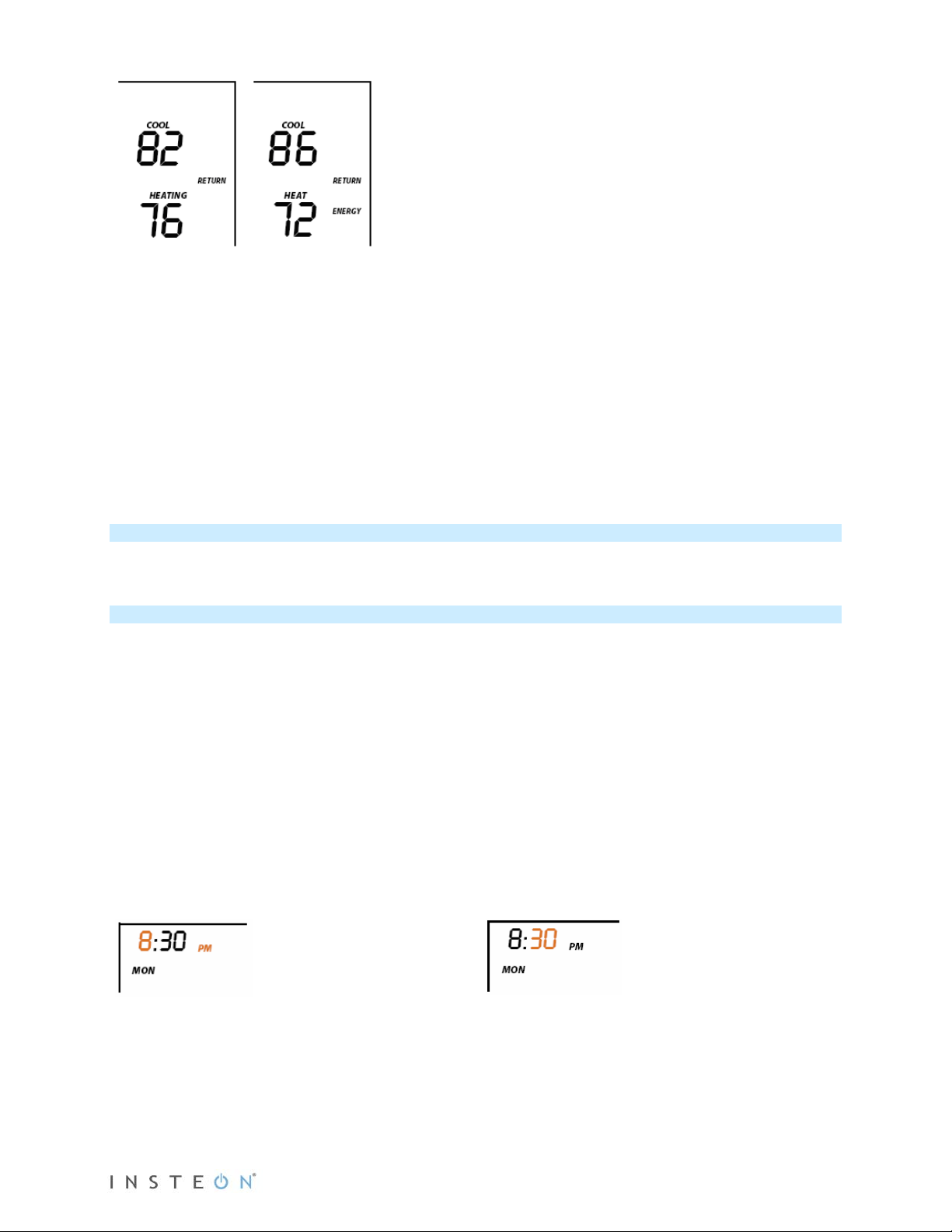
From Time of Day Mode:
First press of Time/Sensor:
Note: AM/PM changes automatically as needed.
Second press of Time/Sensor:
• Both Heat and Cool setpoints changed as
specified.
• Default setback is 4°.
• Notice that “Heating” is active on the left, but
not on the right since the setpoint is lower
than the current temperature; the element
reads “Heat.”
Note: Onscreen text displaying “Heat” changes to “Heating” and “Cool” changes to “Cooling” to indicate
HVAC system is active. The status LED, if enabled, under the door also indicates current active state:
Cooling = green, Heating = red. At time of activation either Heating or Cooling text will blink for 3 seconds
then remain steady during the active cycle.
Set Button Operation
The Set button adds and removes INSTEON Thermostat from INSTEON scenes. It functions like the Set
button on other INSTEON devices.
Time/Sensor Button Operations
• The Time/Sensor button allows the user to set the current day and time.
• It cycles among hour, minute, day and 12/24-hour format.
• Up/Down arrows cycle through the available options.
• Go to the next Time/Sensor step by pressing Time/Sensor button again.
• Exit Time/Sensor setup by:
- Timing out (4 minutes)
- Pressing Mode button
Note: Colored elements indicate LCD element that should be blinking during setting procedure.
Hours settings
• Up/Down arrows cycle through time in 1-hour
increments.
• Pressing and holding Up/Down arrows cycles
through faster.
Page 7 of 28 Rev: 1/21/2014 8:35 AM
Minutes settings
• Up/Down arrows cycle through time in 1-
minute increments.
• Pressing and holding Up/Down arrows
cycles through faster.
Page 8
Third press of Time/Sensor:
Note: AM/PM is not displayed when in 24-Hour format.
Day settings
• Up/Down arrows cycle through each day of the week as shown.
Fourth press of Time/Sensor:
Clock Format setting (12- or 24-Hour clock)
• Entire “time” blinks.
• Up/Down arrows cycle between 12- and 24-hour clock format.
Press Time/Sensor a fifth time to exit.
Program Button Operation
• The Program button allows you to set up the various preprogrammed modes (Wake, Leave, Return
and Sleep).
• Go to the next step by pressing Program again.
• Exit Program setup by:
- Timing out (4 minutes)
- Pressing Mode button
Note: Colored text below indicate element that sh ou ld be blinking during setting procedure.
First press of Program:
Selects from available pre-program modes
Up/Down arrows cycle through Wake, Leave, Return and Sleep.
NOTE:
• Energy is not a part of this option.
• Once a preprogrammed mode is selected, that item remains displayed throughout to
indicate the mode you are programming.
• The current mode settings are displayed on the thermostat at each setup step.
Second press of Program:
Day setting
• Up/Down buttons cycle among all week, weekdays, weekend days and each day, as shown.
Page 8 of 28 Rev: 1/21/2014 8:35 AM
Page 9
Fourth press of Program:
Fifth press of Program:
Third press of Program:
Start Time
• Up/Down arrows cycle through time in 15-minute increments. Note: when pressing the Down arrow, if
you come within 15 minutes of another preprogrammed mode time, you will not be able to increase
the time any further.
• Pressing and holding Up/Down arrows cycles faster.
Note: AM/PM changes automatically as needed.
Note: The start of one program mode is also the end of the previous program mode.
Cool setpoint
• Up/Down arrows cycle through temperature.
Heat setpoint
• Up/Down arrows cycle through temperature.
Sixth press of Program:
• Restarts the process to program another Mode/Day
NOTE: The four modes come preprogrammed. The defaults are for all days:
Day Modes Start Time Thermostat Mode Heat Setting Cool Setting
Wake 6:00AM Auto 65°F (18°C) 75°F (24°C)
Leave 8:30AM Auto 60°F (16°C) 80°F (27°C)
Return 5:00PM Auto 65°F (18°C) 75°F (24°C)
Sleep 11:00PM Auto 60°F (16°C) 80°F (27°C)
Page 9 of 28 Rev: 1/21/2014 8:35 AM
Page 10

Fan and Hold Button Operations
Before pressing Master button:
After pressing and holding Master button:
Always On Auto
Hold On Hold Off
Fan button operations
• The Fan button cycles between Auto and Always On.
• On the display, it simply indicates the text “Fan Always” when selected. There is no indication for Fan
Auto.
Hold button operations
• The Hold button overrides a preprogrammed mode until Hold is turned off.
NOTE:
• While Hold is enabled, the next preprogrammed time that comes in Time of Day Mode will be ignored.
• While Hold is enabled, the preprogrammed time notations are not shown (i.e. Wake, Leave, Return
and Sleep).
• Hold can be remotely enabled/disabled from an INSTEON controller.
Master Button Operation
First press and hold:
Makes the local INSTEON Thermostat the master temperature controller
• To perform this, press and hold Master button for 3 seconds.
INSTEON Thermostat beeps once.
• Release.
Note: This is only valid if at least one INSTEON Thermostat Zone Thermostat is linked to INSTEON
Thermostat.
• Notice that the left remote sensor is currently
the Master temperature controller.
Note: If no INSTEON scene is programmed to a INSTEON Wireless Thermostat, pressing and holding for
3 seconds will cause the Master segment to display while the button is being held.
Page 10 of 28 Rev: 1/21/2014 8:35 AM
• Notice that the left remote sensor is no
longer the Master temperature controller.
• The local INSTEON Thermostat is now the
Master controlling temperature.
Page 11

Installation
Installation should be performed only by a qualified HVAC Technician or a homeowner who is familiar and
comfortable with electrical circuitry. If you have any questions regarding installation, consult an HVAC Technician
CAUTIONS AND WARNINGS
Read and understand these instructions before installing and retain them for future reference.
IMPORTANT: HOW DO I KNOW THIS WILL WORK WITH MY SYSTEM?
1) Your existing HVAC can operate 2 stages of Heat and Cool.
2) Your existing thermostat operates on 24V.
3) Your system is not a heat pump.
4) Your system is not a 120/240V electric radiant heater.
5) Your existing thermostat is not millivolt contr ol led .
6) Your existing thermostat has 5 or more wires connected.
INSTEON Thermostat is designed to operate on a minimum 5-wire, 24V HVAC unit. If you have only 4
wires you can purchase the “Add-A-Wire” adapter item #304AAW from www.smarthome.com.
Note:
or call the INSTEON Support Line at 800-762-7845.
Tools Needed
• Flathead screwdriver
• Wire cutter/stripper
Installation
Proper installation of the INSTEON Thermostat will be accomplished by following these step-by-
step instructions
1) Do not remove wires from existing thermostat until instructed.
2) If you have A/C, turn off A/C breaker.
3) Turn off breaker/fuse to furnace.
4) Remove cover from existing thermostat to gain access to wires (may need to detach from wall).
5) If necessary, take photo of wiring connections to help with reconnec tio ns .
6) If possible while still connected, attach the “C” label to the wire connected to “C” on your
7) Disconnect your C wire from thermostat.
8) Repeat for all your other wires, being careful to not pull off wire stickers or mar paint or wallpaper.
9) Remove existing thermostat back from wall.
10) Remove 3” of the outer jacket from the wires exposing the
11) Slide all wires through large hole in back of INSTEON Thermostat.
12) Mount INSTEON Thermostat to wall.
a. Confirm A/C is off by turning on air and observing that compressor/fan do not come on.
a. If thermostat no longer functions, move to next step.
b. If thermostat still functions, it is probably running off battery power. Try to turn on heat.
i. If heat doesn’t turn on, move to next step.
ii. Otherwise, turn off heat and wait until furnace fan stops, then try another
breaker until heat no longer runs.
thermostat. Otherwise, label C wire once disconnected.
individually colored wires. This ensures the outer insulation does
not press against the internal components of the INSTEON
Thermostat upon closing the unit. Note: if your system has 4
wires, you will need the “Add-a-Wire” adapter. See Cautions and
Warnings above.)
a. Be careful not to tear off the labels that you previously
attached to the wire ends.
b. If you do not have 3” after stripping away the outer
jacket, you can extend the inner wires by splicing on a
new longer conductor.
i. "Thermostat" cabling is available at most home improvement centers. It comes in
different wire configurations, but the same gauge. If the wire you have now is 5conductor cable, buy 5-conductor thermostat wire and connect it matching colorto-color.
c. If wires are longer than 3”, trim them back or make sure you can push the excess back
into the wall. Be careful not to cut off the wire designation label.
Page 11 of 28 Rev: 1/21/2014 8:35 AM
Page 12

13) To ensure accurate temperature readings:
Wire color from furnace/AC unit
Function
Install on INSTEON Thermostat connector
Black or blue
Common 24V
24V COM
Red
Power 24V
24 RH
White
Heat 1
W1
Brown
Heat 2
W2
Green
Fan G Yellow
Cooling 1
Y1
Light blue
Cooling 2
Y2
a. Carefully slide wires through provided black grommet (draft shield). See diagram .
b. Peel off protective backing.
c. Rotate to most convenient orientation for wire entrance.
14) Apply to round grommet placing indentation.
Wire Connections
If the terminal designations on your old thermostat do not match those on INSTEON Thermostat, refer to
the chart below or the wiring diagram that follows:
Wire colors may vary
Diagram below shows inside of INSTEON Thermostat wall mount case:
15) Insert C wire into terminal C and tighten using small screwdriver (either flathead or Philips).
a. Be aware that incorrect connections may cause non-operation or Heat, Cool and Fan to
be wrongly triggered.
16) Repeat for other wires matching terminal designations.
17) Close front of INSTEON Thermostat onto back mounting plate.
a. Press firmly until you feel the connecting pins fully seat into their receptacles. Yo u s houl d
also feel and hear a click as the door latches.
18) Turn breaker(s) back on.
19) Allow 10 seconds for INSTEON Thermostat to boot up.
When screen displays current temperature, INSTEON Thermostat is powered and functional.
Page 12 of 28 Rev: 1/21/2014 8:35 AM
Page 13

Test Operation
Heating Mode Test
1) Press Mode once to enter Heat mode.
2) Tap the Up arrow several times until setpoint is 2° above current temperature.
INSTEON Thermostat will call for heat and “Heat” segment will change to “Heating.”
“Heating” segment will flash for 3 seconds, then remain steady when active.
Status LED will display red if enabled (off by default).
Allow furnace to operate long enough to begin blowing warm air.
3) Tap the Up or Down arrows until you reach a desirable heat temperature setpoint (if this is below
ambient, Heating will go inactive).
Note: Fan stays controlled by HVAC and may continue running for a couple minutes.INSTEON
Thermostat has a default 5-minute delay between Heat and Cool settings.
Cooling Mode Test
1) Tap Mode button again to enter Cool mode.
2) Tap the Down arrow several times until setpoint is 2° below current temperature.
INSTEON Thermostat will call for cooling and “Cool” segment will change to “Cooling.”
“Cooling” segment will flash for 3 seconds, then remain steady when active.
Status LED will display green.
Allow A/C to operate long enough to begin blowing cool air.
3) Tap the Up or Down arrows until you reach a desirable cool temperature setpoint (if above ambient,
Cooling will go inactive).
Note: Fan will turn on and off with Cooling.
Auto Mode Test
1) Tap Mode once to enter Auto mode.
2) Note that your Heat and Cool setpoints are both as set in previous steps, unless you did not have a
minimum 2° gap between settings.
3) Tap Up arrow once to increase both Heat and Cool setpoints by 1°.
4) Tap Down arrow once to decrease both Heat and Cool setpoints by 1°.
5) Tap Mode once to enter Time of Day mode.
Indicated by Auto at bottom and relevant time of day (Wake, Leave, Return, Sleep) to right of
Heat/Cool set temps.
6) Tap Mode once more to return to Off mode.
Adding an INSTEON Wireless Therm os t a t
INSTEON Thermostat can synchronize with a INSTEON Wireless Thermostat to provide a portable
thermostat wherever you want temperature control. You can add up to two INSTEON Wireless
Thermostats.
1) Press and hold Set button on INSTEON Wireless Thermostat.
INSTEON Wireless Thermostat Set LED will blink green and unit will beep.
2) Press and hold INSTEON Thermostat Set button.
INSTEON Thermostat will beep, then double-beep.
INSTEON Wireless Thermostat will double-beep.
3) Test the scene by pressing and holding the Master button on the INSTEON Thermostat.
• When properly added, pressing the Master button on the INSTEON Thermostat will illuminate the
“Master” segment on that same screen. Additionally, the present room temperature of the
INSTEON Wireless Thermostat will be displayed in positi on 1 as the small temperature segments
at top center of the display.
• A visual inspection of each display will reveal the Master status of each INSTEON Thermostat or
Zone Thermostat.
Note: Only the INSTEON Thermostat is directly connected to the HVAC system via wires. If you plan on
operating multiple INSTEON Wireless Thermostats you must have at least one INSTEON Thermostat to
control the HVAC.
Page 13 of 28 Rev: 1/21/2014 8:35 AM
Page 14

INSTEON Programming
Add INSTEON Thermostat as an INSTEON Controller
INSTEON Thermostat can be set up to control other INSTEON devices or trigger software events when
there is a change. The following INSTEON Thermostat changes can be configured as a controller:
• Group 1 - Cooling mode change (scene control)
• Group 2 - Heating mode change (scene control)
• Group 3 - Dehumidifiation, high humidity setpoint (scene control)
• Group 4 - Humidification, low humidity setpoint (scene control)
• Group EF - Broadcast on any change (notification group for linked software controllers)
NOTE: An INSTEON Wireless Thermostat can also be added to a scene as a controller to Groups 1 - 4.
When it is added as a controller of a INSTEON Thermostat, the setpoints between INSTEON Wireless
Thermostat and INSTEON Thermostat will always be matched. When it is not added as a controller to a
INSTEON Thermostat, the setpoints are local only. INSTEON Wireless Thermostat will send group
commands based on local temperature or humidity level and the setpoint shown on the display,
regardless of whether it’s added as a controller to a INSTEON Thermostat.
Note: Humidity levels are taken from the local device only; they are not shared or matched among
thermostats.
1) Press and hold INST EON T hermostat’s Set button until it beeps.
INSTEON Thermostat will beep.
INSTEON Thermostat Set LED will blink green.
2) Tap Up or Down arrows to select from Groups 1-4 to add to a scene.
• Group 1 – Cooling mode change (default)
• Group 2 – Heating mode change
• Group 3 – Dehumidification, high humidity setpoint
• Group 4 – Humidification, low humidity setpoint
3) Adjust scene responder (such as OutletLinc with connected humidifier) to the state you want when
scene is activated (e.g., 50%, 25% or even Off).
4) Press and hold responder’s Set button until it double-beeps or its LED flashes.
INSTEON Thermostat will double-beep upon completion.
LED will return to previous state.
5) Confirm scene addition was successful by raising or lowering INSTEON Thermostat’s setpoint to
activate the particular mode.
After INSTEON Thermostat changes to active mode set in step 2 above, responder will toggle
between the scene’s on-level and off.
6) To add more responders to the scene, repeat steps 1-5 for each additional responder.
2
1
Upon entering scene mode, this screen wi ll dis play for ~ 2 seconds.
1
Group FE is a hexadecimal representation of Group 254 and can only be configured using software.
2
If the responder is a multi-scene device such as a KeypadLinc, tap the scene button you wish to control until its LED is in the desired scene state (on or off).
Page 14 of 28 Rev: 1/21/2014 8:35 AM
Page 15

LCD display after 2 seconds.
LCD display when using Up or Down arrows to select from the 4 controller groups.
Page 15 of 28 Rev: 1/21/2014 8:35 AM
Page 16

Removing INSTEON Thermostat as an INSTEON Controller
If you want to remove INSTEON Thermostat from a scene as a controller, follow instructions below.
Whenever possible, use software for managing scene memberships.
Note: If you choose to remove INSTEON Thermostat from use, it is important that you remove scene
memberships from all responders. Follow the instructions below for each responder of which INSTEON
Thermostat is a member.
1) Press and hold INSTEON T herm os tat’s Set button until it beeps.
INSTEON Thermostat Set LED will blink green.
INSTEON Thermostat will beep.
2) Press and hold INSTEON Thermostat’s Set button again to put it in scene mode.
INSTEON Thermostat Set LED will blink red.
INSTEON Thermostat will beep.
LCD display indicates the group from which you are removing the scene.
3) Tap Up and Down arrows to select appropr ia te group to remove from:
• Group 1 - Cooling mode change, default
• Group 2 - Heating mode change
• Group 3 - Dehumidifiation, high humidity setpoint
• Group 4 - Humidification, low humidity setpoint
4) Press and hold responder’s Set button.
INSTEON Thermostat will double-beep upon completion.
LED will return to previous state.
Upon entering Add to a Scene mode.
Upon entering Remove from a Scene mode (defaults to Cooling mode).
Page 16 of 28 Rev: 1/21/2014 8:35 AM
Page 17

LCD display when using Up or Down arrows to select from the 4 controller Groups.
Add INSTEON Thermostat as an INSTEON Responder
Add a scene to an incoming ON command
1) Set INSTEON Thermostat to desired state (mode, setpoint, fan state, energy button state).
2) Put controller in linking mode (press and hold controller Set button until it beeps).
3) Press and hold INSTEON T herm os tat’s Set button.
INSTEON Thermostat Set LED will blink green and unit will beep.
INSTEON Thermostat will double-beep.
LED will return to previous state.
Add a scene to an incoming OFF command
1) Set INSTEON Thermostat to desired state.
2) Put controller in linking mode (press and hold controller Set button).
3) Simultaneously press and hold INSTEON Thermostat’s Set button and Down arrow.
INSTEON Thermostat Set LED will blink green and unit will beep.
INSTEON Thermostat will double-beep.
LED will return to previous state.
Display while in Add to a Scene Mode to ON or OFF
Remove INSTEON Thermostat as an INSTEON Responder
If you want to remove INSTEON Thermostat from a scene, follow instructions below. Whenever possible,
use software for managing scene memberships.
Note: If you choose to remove INSTEON Thermostat from use, it is important that you remove scene
memberships from all controllers. Otherwise, controllers will retry commands repetitively, creating network
delays. Follow the instructions below for each scene controller of which INSTEON Thermostat is a
member.
Page 17 of 28 Rev: 1/21/2014 8:35 AM
Page 18

Removing a scene from an incoming ON command
1) Press and hold controller’s scene button until controller beeps.
1
Controller’s LED will blink.
2) Press and hold controller’s scene button again until controller beeps again.
Controller’s LED will continue blinking.
3) Press and hold INSTEON T herm os tat’s Set button.
INSTEON Thermostat Set LED will blink green and unit will beep.
INSTEON Thermostat will double-beep.
LED will return to previous state.
Controller’s LED will stop blinking.
3) Confirm scene removal was successful by tapping the controller scene button you just removed.
INSTEON Thermostat will no longer respond.
Removing a scene from an incoming OFF command
1) Press and hold controller’s sc ene button unt il controller beeps.
Controller’s LED will blink.
2) Press and hold controller’s scene button until controller beeps again
Controller’s LED will continue blinking.
3) Simultaneously press and hold INSTEON Thermostat’s Set button and Down arrow.
INSTEON Thermostat Set LED will blink green and unit will beep.
INSTEON Thermostat will double-beep.
LED will return to previous state.
Controller’s LED will stop blinking.
4) Confirm scene removal was successful by tapping the controller scene button you just removed.
INSTEON Thermostat will no longer respond.
1
For devices without beepers hold until its LED begins blinking (this may take 10+ seconds)
Page 18 of 28 Rev: 1/21/2014 8:35 AM
Page 19

User Setup Mode Overview
Press and hold Program button for 3 seconds or more to enter the User Setup Mode.
User Setup Mode
1) Press and hold Program button to access the following options:
• Press Mode to step between menu items (sub-mode number will appear on top of the screen).
o Sub-mode 01: Display LED on-time select (default is 10 seconds)
o Sub-mode 02: Humidity low setpoint (default is 30%)
Page 19 of 28 Rev: 1/21/2014 8:35 AM
Page 20

o Sub-mode 03: Humidity high setpoint (default is 90%)
o Sub-mode 04: Temperature format select (default is Fahrenheit)
o Sub-mode 05: Beep on button press (default is Off)
o Sub-mode 06: Status LED (default is Off)
o Sub-mode 07: Button lock (default is Off)
o Sub-mode 08: Programming lock (default is Off)
o Sub-mode 09: Activation delay (default is 5 minutes)
Press the Up or Down arrow to change a setting.
• Sub-mode 01: LED backlight ON time (10–second default)
a. Tap Up or Down arrow to step between Off, 10 sec, 60 sec and On
b. Use HouseLinc software to set the LED backlight ON-time in 1-second intervals
• Sub-mode 02: Humidity low setpoint (humidification, 30% default)
a. Up arrow = Increase humidity % setpoint
b. Down arrow = Decrease humidity % setpoint
c. Range = 0 to 79%
• Sub-mode 03: Humidity high setpoint (dehumidification, 90% default)
a. Up arrow = Increase humidity % setpoint
b. Down arrow = Decrease humidity % setpoint
c. Range = 20 to 90%
• Sub- mode 04: Temperature format select (C or F, F default)
a. Up arrow = C
b. Down arrow = F
• Sub-mode 05: Beep on button press (enable/disable, OFF default)
a. Up arrow = ON
b. Down arrow = OFF
• Sub- mode 06: Status LED (enable/disable, OFF default)
a. Up arrow = ON
b. Down arrow = OFF
Page 20 of 28 Rev: 1/21/2014 8:35 AM
Page 21

Sub- mode 07: Button lock (disables front button presses, OFF default)
o For high-traffic common area locations, such as a business lobby.
a. Up arrow = ON
b. Down arrow = OFF
• Sub- mode 08: Programming lock (locks out Set button programming operations, OFF default)
a. Up arrow = ON
b. Down arrow = OFF
• Sub- mode 09: Delay between consecutive AC modes (5-m inute def aul t)
a. Up arrow = Adds 1-minute increments
b. Down arrow = Decreases 1-minute increments
c. Range = 2-20 minutes
Temperature and Humidity Calibration Mode
Note: Use a calibrated temperature or humidity source when adjusting INST EON T hermostat
1) Press and hold the Program button, tap Time/Sensor to enter Temperature Calibration Mode.
2) Tap Mode to step between temperature calibration and humidity calibration.
Temperature Calibration
• The top left number (77 in example) is the current reading according to the temperature sensor.
• The top right number (14 in example) is the current offset (represents 1.4).
• These numbers can change while this screen is displayed even though the primary temperature
does not change. They are floating point calculations.
3) Tap Up or Down arrows to adjust the displayed temperature to match the calibrated source.
i. Each press results in a 1° F (0.5° C) change.
ii. The calculation using example numbers below is 78 = 77 + 1.4.
iii. The offset range is from –10 to +10 ac tu al degre es .
Humidity Calibration Mode
Page 21 of 28 Rev: 1/21/2014 8:35 AM
Page 22

1) Once in Setup Mode for temperature calibration (step 1 above), tap Mode button to step between
temperature calibration and humidity calibration.
2) Press the Up or Down arrow to select the current humidity level.
• The top left number (40 in example) is the current reading according to the humidity sensor.
• The top right number (-92 in example) is the current offset (represents -9.2).
• These numbers can change while this screen is displayed even though the primary hum id it y level
does not change. They are floating point calculations.
i. Each press results in a 1% humidity change.
ii. The calculation using example numbers below is (31 = 40 – 9.2) and 42 = 40 + 1.7.
iii. The offset is from -10 to +10.
3) Press Program to exit calibration mode.
Advanced 2-Stage Heating or Cooling Systems
Two-stage air conditioners offer a more efficient, energy-saving way to cool your home. Two-stage
cooling means that the air conditioner has a compressor with two levels of operation. A 2-stage unit
produces more even heating and cooling temperatures.
INSTEON Thermostat’s second stage of heat or cool engages under the following conditions:
• INSTEON Thermostat’s setpoint is set at 5°(F or C) or more below ambient in Cool mode and
5°(F or C) or more above ambient in Heat mode.
- Heat mode setpoint is 80°, ambient is 72° = first and second stage engaged
- Cool mode setpoint is 78°, ambient is 84° = first and second s ta ge eng aged
• INSTEON Thermostat has been active in Heat or Cool for longer than 10 minutes and did not
reach setpoint.
- Heat mode ran for 10 minutes and did not reach setpoint = second s t age eng ag ed.
- Cool mode ran for 10 minutes and did not reach setpoint = second stage engaged .
Note: It is possible for INSTEON Thermostat to occasionally engage and disengage second stage during
a single heating or cooling cycle as variables are met.
Factory Reset
If you want to reset INSTEON Thermostat to its factory default settings, follow instructions below.
Note: If you choose to reset INSTEON Thermostat to its factory default settings, it is important that you
remove scene memberships from all controllers. Otherwise, controllers will retry commands repetitively,
creating network delays. Follow the instructions in Removing INSTEON Thermostat as an INSTEON
Responder above for each scene controller of which INSTEON Thermostat is a member.
Factory reset changes:
• INSTEON is reset (all scene memberships are removed)
• Day/time is changed to 12:00AM Monday
• Programming times, temperatures and other settings are reset to their default values
Factory reset does not change:
Page 22 of 28 Rev: 1/21/2014 8:35 AM
Page 23
• Temperature offset
General
Product name
INSTEON Thermostat
Brand/manufacturer
INSTEON
2441TH US
813922-010824 US/Can
Warranty
2 years, limited
INSTEON
INSTEON powerline mesh repeater
No
INSTEON RF mesh repeater
Yes
INSTEON controller
Yes
INSTEON responder
Yes
Maximum links/scenes
400
Red when Heating is active, green when Cooling is active
LED brightness
LED can be enabled or disabled locally or via software
Local control
Yes
On
Off
Beep
• Humidity offset
Factory Reset
1) Press and hold INSTEON T herm os tat’s Set button until it beeps.
INSTEON Thermostat will beep.
INSTEON Thermostat Set LED will blink green.
2) Press and hold INSTEON T herm os tat’s Set button again until it beeps.
INSTEON Thermostat will beep.
INSTEON Thermostat Set LED will blink red.
3) Double-tap Set button.
4) Press and hold Set button again for about 10 seconds.
INSTEON Thermostat will emit a long beep and its display will blink all segments.
5) When blinking/buzzing stops, release Set button and wait 10 secon ds .
INSTEON Thermostat will perform a series of self tests, then return to normal operations.
INSTEON Thermostat display will return to normal.
Specifications
Manufacturer product number
UPC
LED
Commands supported as controller On Off
2732-422 EU
2732-522 AUS/NZ
813922-012859 EU
813922-012866 AUS/NZ
Off when neither mode is active
Blinks red or green during setup
Commands supported as responder
Page 23 of 28 Rev: 1/21/2014 8:35 AM
Page 24

Software configurable
Yes
RF range
Up to 150-Feet (50m) open air
Phase bridge detect beac o n
No, RF only device
INSTEON device category
INSTEON device subcategory
2732-522 (921 MHz)
0x10
X10
X10 address
N/A
X10 transmitter
N/A
X10 receiver
N/A
X10 status response
N/A
X10 resume dim
N/A
X10 minimum transmit level
N/A
X10 minimum receive level
N/A
X10 messages repeated
N/A
Mechanical
Mounting
Common 24V
Power 24V
Heat 1
Heat 2
Fan
Cooling 1
Cooling 2
Screw clamp connections
Yes, 10 position
Case color
White
Set button
1
Plastic
UV stabilized ABS
Beeper
Yes
Beep on button press
Optional (off by default)
LED
1 dual-color red/green
Dimensions
5.7” x 3.6” x 1.1” (14.5cm x 9.1cm x 2.8cm)
Weight
0.46 lbs, 7.4oz., 208g
Operating environment
Indoors
Operating temperature range
Operating humidity range
0-90% relative humidity
Storage temperature range
Electrical
Voltage
24VAC
Wire connections
0x05 (all frequencies)
2441TH (915 MHz) 0x0B
2732-422 (869 MHz) 0x0F
Wall mount
Page 24 of 28 Rev: 1/21/2014 8:35 AM
4o to 40o C (39o to 104o F)
-20 o to 70 o C (-4 o to 158 o F)
Page 25

Frequency
50/60 Hz
Load type(s)
HVAC
Maximum load
N/A
Minimum load
N/A
User replaceable fuse
No
Hardwired remote control
N/A
Retains all settings without power
Yes, saved in non-volatil e EE P RO M
Standby power consumption
< 0.75 watts
FCC ID Pat 15B & 15C and IC: RSS-210 Issue 8 (US/Can)
FCC I.D.
SBP2441T
WEEE, RoHS (All models)
Safety approval(s)
N/A, low voltage device
Problem
Possible cause
Solution
After screwing into wall,
time staying closed.
The protective shielding on the
components.
Strip back protective shielding so
The A/C is not working after
You may have accidentally
shorted the transformer.
Replace the common wire.
After powering up or a factory
temperature.
It didn’t boot up fully.
Open INSTEON Thermostat and
INSTEON Support Line.
I replaced my INSTEON
SmartLinc and the INSTEON app
thermostat’s I.D.
Update the INSTEON I.D. on
Note: This is an RF device. Frequency shown because AC
provided from HVAC system.
Certifications
Marks
Troubleshooting
INSTEON Thermostat’s front
face pops open and has a hard
installing INSTEON Thermostat.
reset, INSTEON Thermostat
displays a two-digit error code
instead of the ambient
ETSI EN 300 220-1 & 220-2, ETSI EN 301 489-1 & 489-3 (Eu)
AS/NZ 4268 (C-Tick N16509)
C-Tick N16509 (Aus/NZ model)
cable jacket was not stripped
back enough, interfering with
shorted the common wire, which
face snaps in securely.
tap the reset button. Close the
unit and wait for it to reboot. If
problem persists, call the
Thermostat with a new one, but
now SmartLinc and INSTEON
app don’t recognize it.
Page 25 of 28 Rev: 1/21/2014 8:35 AM
communicate via INSTEON I.D.s.
They are still trying to
communicate to the old
both SmartLinc and the
INSTEON app with your new
thermostat’s I.D.
Page 26

DECLARATION OF CO NFO RMITY
Hereby, INSTEON declares that this device is in compliance with the essential requirements and other
relevant provisions of the following Directives:
1) Electromagnetic Compatibility Directive 2004/108/EC
2) Hazardous Substance Directiv e 200 5/95 /EC
Technical data and copies of the original Declaration of Conformity are available and can be obtained
from INSTEON; 16542 Millikan Ave, Irvine, CA, USA.
User Information for Consumer Products Covered by EU Directive 2002/96/EC on Waste Electric
and Electronic Equipment (WEEE)
This document contains important information for users with regards to the proper disposal and recycling
of INSTEON products. Consumers are required to comply with this notice for all electronic products
bearing the following symbol:
Environmental Information for Customers in the European Union
European Directive 2002/96/EC requires that the equipment bearing this symbol on the product and/or its
packaging must not be disposed of with unsorted municipal waste. The symbol indicates that this product
should be disposed of separately from regular household waste streams.
It is your responsibility to dispose of this and other electric and electronic equipment via designated
collection facilities appointed by the government or local authorities. Correct disposal and recycling will
help prevent potential negative consequences to the environment and human health.
For more detailed information about the disposal of your old equipment, please contact your local
authorities, waste disposal service, or the shop where you purchased the product.
DECLARATION OF CONFORMITY TO R&TTE DIRECTIVE 1999/5/EC for the European Community,
Switzerland, Norway, Iceland and Liechtenstein
Product category: general consumer (category 3).
English: This equipment is in compliance with the essential requirements and other relevant provisions of
the European R&TTE Directive 1999/5/EC
Deutsch [German]: Dieses Gerät entspricht den grundlegenden Anforderungen und den weiteren
entsprechenden Vorgaben der Richtlinie 1999/5/EU.
Nederlands [Dutch]: Dit apparaat vo ld oet aan de essentie le eise n en ander e va n toep ass ing zijn de
bepalingen van de Richtlijn 1999/5/ EC.
Svenska [Swedish]: Denna utrustning står I överensstämmelse med de väsentliga egenskapskrav och
övriga relevanta bestämmelser som framgår av direktiv 1999/5/EG.
Français [French]: Cet appareil est conforme aux exigences essentielles et aux autres dispositions
pertinentes de la Directive 1999/ 5/ EC
Español [Spanish]: Este equipo cumple con los requisitos esenciales asi como con otras disposiciones de
la Directiva 1999/5/CE.
Page 26 of 28 Rev: 1/21/2014 8:35 AM
Page 27

Português [Portuguese]: Este equipamento está em conformidade com os requisitos essenciais e outras
provisões relevantes da Directiva 1999/5/EC.
Italiano [Italian]: Questo apparato é conforme ai requisiti essenziali ed agli altri principi sanciti dalla
Direttiva 1999/5/CE.
Norsk [Norwegian]: Dette utstyret er i samsvar med de grunnleggende krav og andre relevante
bestemmelser i EU-d irektiv 1999/5/EF.
Suomi [Finnish]:Tämä laite tÿttää direktiivin 1999/5/EY olennaiset vaatimukset ja on siinä asetettujen
muiden laitetta koskevien määräysten mukainen.
Dansk [Danish]: Dette udstyr er i overensstemmelse med de væsentlige krav og andre relevante
bestemmelser i Direktiv 1999/5/EF.
Polski [Polish]: Urządzenie jest zgodne z ogólnymi wymaganiami oraz szczególnymi warunkami
okreslonymi Dyrektywą UE: 1999/5/EC
Page 27 of 28 Rev: 1/21/2014 8:35 AM
Page 28

Certification and Warranty
FCC and Industry Canada Compliance Statement
This device complies with FCC Rules Part 15 and Industry Canada RSS -210. Operation is subject to the following two conditions:
(1) This device may not cause harmful interference, and
(2) This device must accept any interference, including interference that may cause undesired operation of the device.
Le present appareil e st c o nf orm e a u x CNR d' Ind us tri e C a na da appli c ables aux apparei ls r adio exempts de licence. L'exploit ati on es t aut ori s e a u x deux
conditions suivantes:
(1) l'appareil ne doit pas produire de brouillage, et
(2) l'utilisateur de l'appareil doit accepter tout brouillage radiolectrique subi, mme si le brouillage est susceptible d'en compromettre le
fonctionnement.
The digital circuitry of this device has been tested and found to comply with the limits for a Class B digital device, pursuant to Part 15 of the FCC Rules.
These limits are designed to pro vide reasonable protection agai nst harmful inte rference in resid ential installatio ns. This equipm ent generates, uses,
and can radiate radio freque ncy energ y and, if not installe d and used in acco rdance with the instructi ons, may caus e harmful inte rference to ra dio and
television reception. However, there is no guarantee that interference will not occur in a particular installation. If this device does cause such
interference, which ca n be ve rif ie d b y t urni ng th e dev i ce off a nd o n, th e us e r is enc o ur age d to eli m ina t e th e inte rf e re nce b y one or more of the followi ng
measures:
- Re-orient or relocate the receiving antenna of the device experiencing the interference
- Increase the distance between this device and the receiver
- Connect the device to an AC outlet on a circuit different from the one that supplies power to the receiver
- Consult the dealer or an experienced radio/TV technician
WARNING: Chang es or m odificati ons t o this device not expr essly ap proved by th e part y responsi ble for compli ance c ould voi d the us er’s a uthorit y to
operate the equipment.
Limited Warranty
Seller warrants to the origin al consumer pur chaser of thi s product th at, for a peri od of two ye ars from the date of purcha se, this prod uct will be f ree
from defects in mate rial and workmanship a nd will perform in substan tial conformity to the descri ption of the product in t his Owner’s Manual. This
warranty shall not appl y to defec ts or errors caus ed by misuse o r neglect. If the product is f ound to be def ective in material or workmanshi p, or if the
product does not perform as warr anted above during the warranty perio d, Seller will either repair it, replace it, or refund the purch ase price, at its
option, upon receip t of the p roduct at t he addr ess belo w, pos tage p repai d, with proof of th e date of purcha se and a n e xplana tion of the de fect or e rror.
The repair, replacem ent, or refund that is provided for ab ove shall be the full extent of Seller’s lia bility with respect to this product. For repair or
replacement durin g the warra nty peri od, call th e INSTEO N Suppo rt Line at 800-762-7845 with the Mod el # and Re vision # o f the devic e to recei ve an
RMA# and send the product, along with all other required materials to:
INSTEON
ATTN: Receiving
16542 Millikan Ave.
Irvine, CA 92606-5027
Limitations
The above warrant y is in lieu of and Seller discl aims all other warranties, w hether oral or written, express or implied, including any warr anty or
merchantability or fitness for a p articular pur pose. Any implie d warranty, incl uding any warra nty of mercha ntability or fit ness for a partic ular purpose,
which may not be di sclaim ed o r su ppla nted as prov ided above sh all be l imited to t he two-year of the express warrant y above. No other re presenta tion
or claim of any nature by any person shall be binding upon Seller or modify the terms of the above warranty and disclaimer.
Home automation devices have the risk of failure to operate, incorrect operation, or electrical or mechanical tampering. For optimal use, manually verify
the device state. Any home automation device should be viewed as a convenience, but not as a sole method for controlling your home.
In no event shall Seller be liable f or special, inci dental, conseque ntial, or other dam ages resulting from possession or use of this device, i ncluding
without limitation damage to pr op ert y a nd, to t he e xt ent p erm i tte d by law, personal inj u r y, ev e n if Seller knew or s ho uld have known of the possibil ity of
such damages. Som e st at es d o n ot all ow limitations o n ho w l on g an im pl i ed w arr an t y last s an d/ o r th e e xcl usi o n o r li m itati on of d am age s , in w hich case
the above limitations and/or exclusions may not apply to you. You may also have other legal rights that may vary from state to state.
U.S Patent No. 7,345,998, International patents pending
© Copyright 2012 INSTEON, 16542 Millikan Ave., Irvi ne, CA 9260 6, 80 0-762-7845, www.insteon.com
Page 28 of 28 Rev: 1/21/2014 8:35 AM
 Loading...