

Page 1
INSTEON
®
Wireless Thermostat
Owner’s Manual
2732-232, 2441ZTH (US)
2732-432 (EU)
2732-532 (AUS/NZ)
Page 1 of 27 Rev: 1/21/2014 8:36 AM
Page 2

What’s in the Box? 3
INSTEON Wireless Thermostat Button Overview 4
INSTEON Wireless Thermostat Opera tion and Programming 5
Mode Button Operation 5
Energy Button Operation 6
Set Button Operation 7
Time/Sensor Button Operations 7
Program Button Operation 8
Fan and Hold Button Operations 9
Master Button Operation 10
Optional Accessories 11
Waterproof Temperature Sensor (2433A3) 11
Power Supply 11
Installation 11
Preparation 11
Test Operation 12
Adding INSTEON Wireless Thermostat to an INSTEON Thermostat 12
INSTEON Programming 13
Add INSTEON Wireless Thermostat as a Controller 13
Remove INSTEON Wireless Thermostat as a Controller 14
User Setup Mode Overview 15
User Setup Mode 16
Temperature and Humidity Cal ibrat ion Modes 18
Advanced 2-Stage Heating or Cooling Systems 20
Factory Reset 20
Specifications 21
Troubleshooting 23
Certification and Warranty 26
FCC and Industry Canada Compliance Statement 26
Limited Warranty 27
Limitations 27
Page 2 of 27 Rev: 1/21/2014 8:36 AM
Page 3

What’s in the Box?
• INSTEON Wireless Thermostat
• Quick Start Guide
• Tabletop stand (removable for wall-mounting)
Page 3 of 27 Rev: 1/21/2014 8:36 AM
Page 4
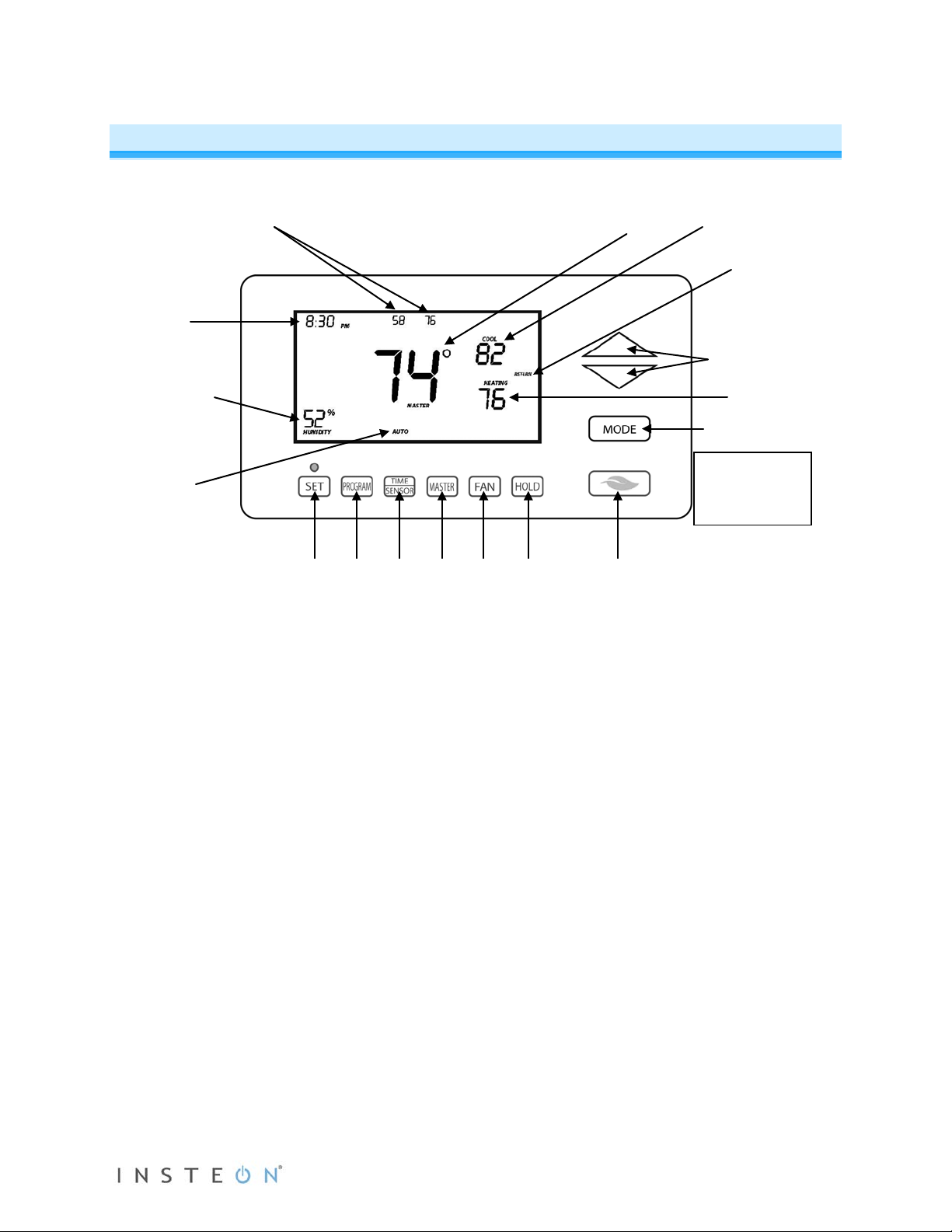
2 4 5 6 7 8 9 3
INSTEON Wireless Thermostat
The gray buttons
Cool setpoint
Heat setpoint
Programmed
Humidity level
Time
Current
Temperature(s) of external
thermostat
Current
Heat or Cool
1
INSTEON Wireless Thermos t a t Button Over vi ew
sensor and/or wireless
temperature
thermostat
mode:
Off, Auto,
auto state
are under the
INSTEON
Thermostat door
1) Up/Down adjusts the temperature setpoint based on the current mode
2) Mode allows the user to select the current operational mode of the HVAC system. It cycles
between Off, Heat, Cool, Auto and Programmed Auto.
3) Energy button is a quick option that saves energy (and money). When pressed, it sets back the
setpoint by a specified value. The default value is 4° from the current setting. To change the
default offset value to be a value other than 4°, you must use software, such as HouseLinc.
4) Hold overrides a pre-programmed mode
5) Fan cycles between Auto and Always On
6) Master makes this device the master temperature controller. Pressing and holding “Master” does
not alter any scene or screen settings. It just defines this INSTEON Wireless Thermostat as the
master temperature controller.
7) Time/Sensor button allows you to set the date and time. It cycles between hour, minute and time
format.
8) Program button allows you to setup the various pre-programmed user modes
9) Set button adds and removes INSTEON Wireless Thermostat from scenes. It functions like the
Set button on other INSTEON devices.
Page 4 of 27 Rev: 1/21/2014 8:36 AM
Page 5
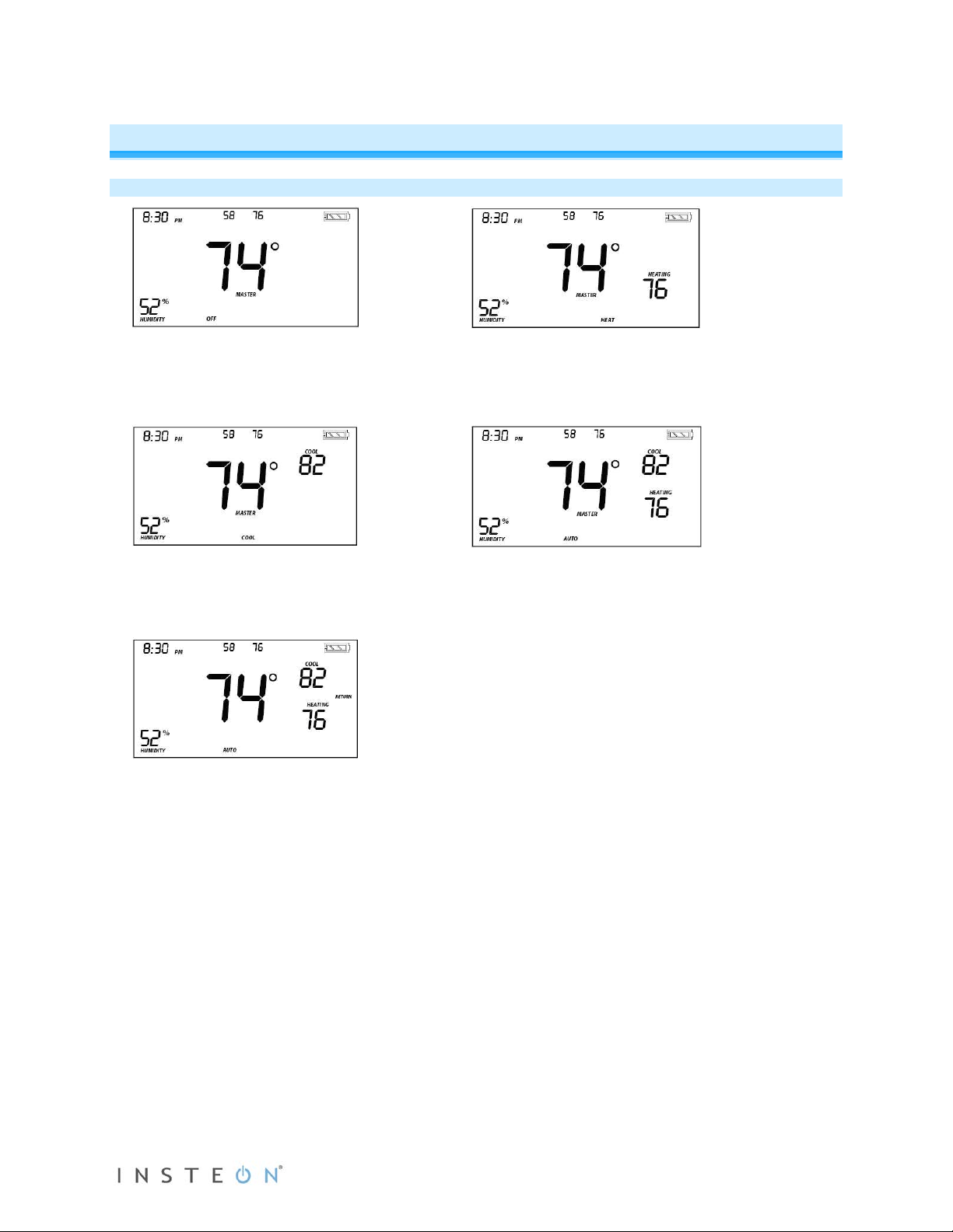
Off Mode:
Heat Mode:
Cool Mode:
Auto Mode:
Programmed Auto Mode:
INSTEON Wireless Thermos t a t Oper a t ion and Programming
Mode Button Operation
• No setpoints are shown
• Up/Down arrows do not do anything
• Only Cool setpoint is shown
• Up/Down arrows change Cool setpoint
• Cool setpoint range: 37°-97°F (4°C-38°C)
• The active program mode is indicated by
one of four annotations: Wake, Leave,
Return or Sleep
• The annotation (Wake, Leave, Return or
Sleep) is not displayed in the other four
modes (Off, Heat, Cool or Auto)
• Both Cool and Heat setpoints are shown
• Up/Down arrows increase or decrease
values by the same amount
• When the thermostat moves to the next
time period, the setpoints will be adjusted
accordingly
• Only Heat setpoint is shown
• Up/Down arrows change Heat setpoint
• Heat setpoint range: 35°-95°F (2°C-36°C)
• Both Cool and Heat setpoints are shown
• Up/Down arrows increase or decrease
values by the same amount
Note:
• To adjust the gap between setpoints in Auto mode, press Mode to select Heat and set the
temperature you desire. Press Mode again to select Cool and set the temperature you desire.
Press Mode a third time to return to Auto; the settings will reflect your changes.
Page 5 of 27 Rev: 1/21/2014 8:36 AM
Page 6
• If you set Heat and Cool to the same temperature setpoint, Heat will automatically move
From Off Mode:
From Heat Mode:
From Cool Mode:
From Auto Mode:
down 2° (the minimum allowable gap).
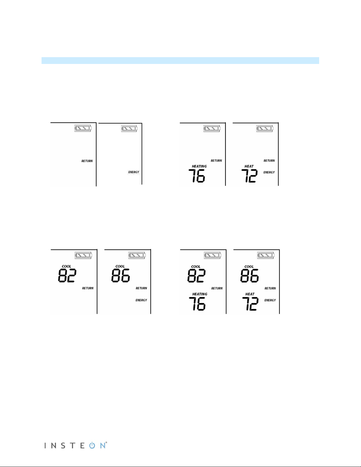
Energy Button Operation
The Energy button (designated with the leaf) is a quick, efficient energy-saving optio n. When you press
the Energy button, INSTEON Wireless Thermostat will adjust the Heat and Cool setpoints by a specified
value. The default value is 4° from the current setting, but can be changed via home control software
such as HouseLinc.
• When you exit Energy mode, it will revert back the 4° that was changed upon entry.
• The unit remains in Energy mode until the Energy button is pressed again.
• Up/Down arrows adjust the temperature setpoint based on the mode you are in.
• Energy button does nothing because the
system is off (at maximum energy savings
already)
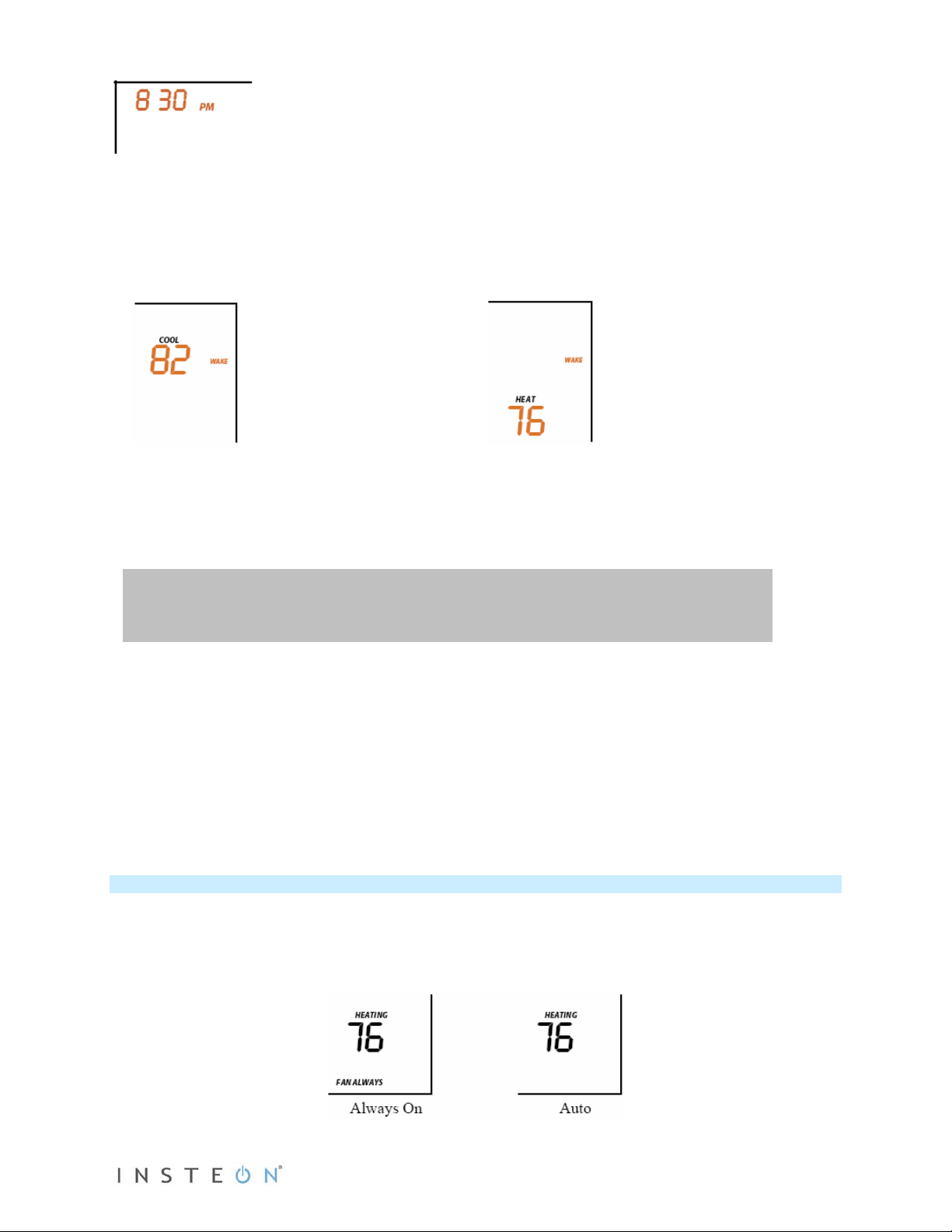
• When “Energy” appears on the screen for
Auto, Cool and Heat Modes, the 4°
setback is engaged
• Cool setback as specified
• Default setback is 4° more
• Heat setback as specified
• Default setback is 4° less
• Notice that “Heating” is active on the left,
but not on the right since the setpoint is
lower that the actual temperature; the
element reads “Heat”
• Both Heat and Cool setpoints changed as
specified
• Default setback is 4° more for Cooling and
4° less for Heating
• Notice that “Heating” is active on the left,
but not on the right since the setpoint is
lower that the actual temperature; the
element reads “Heat”
Page 6 of 27 Rev: 1/21/2014 8:36 AM
Page 7

From Programmed Auto Mode:
element reads “Heat”
First press of Time/Sensor:
Note: AM/PM changes automatically as needed.
Second press of Time/Sensor:
• Both Heat and Cool setpoints changed as
specified
• Default setback is 4°
• Notice that ”Heating” is active on the left,
but not on the right since the setpoint is
lower than the current temperature; the
Note: Onscreen text displaying “Heat” changes to “Heating” and “Cool” changes to “Cooling” to indicate
HVAC system is active.
Set Button Operation
The Set button adds and removes INSTEON Wireless Thermostat from INSTEON scenes. It functions
like the Set button on other INSTEON devices.
Time/Sensor Button Operations
• The Time/Sensor button allows the user to set the time and clock format.
• Button cycles among hour, minute and 12-/24-hour format. Note: When added to a scene with
INSTEON Thermostat, INSTEON Wireless Thermostat automatically retrieves time settings from
INSTEON Thermostat.
• Up/Down arrows cycle through the available options.
• Go to the next Time/Sensor step by pressing Time/Sensor button again.
• Exit Time/Sensor setup by:
- Letting it time out after 4 minutes.
- Pressing Mode button
IMPORTANT! Once you have added INSTEON Wireless Thermostat to a scene in INSTEON Thermostat
as a wireless temperature zone, the Time/Sensor button will allow you to change time format (12- or 24hour) but time information will be provided by INSTEON Thermostat.
Note: Colors indicate element that is presently blinking during setting procedure.
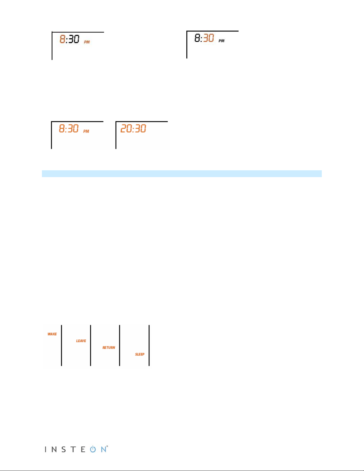
Hours settings
• Up/Down arrows cycle through time in 1-
hour increments
• Pressing and holding Up/Down arrows
cycles through faster
Page 7 of 27 Rev: 1/21/2014 8:36 AM
Minutes settings
• Up/Down arrows cycle through time in 1-
minute increments
• Pressing and holding Up/Down arrows
cycles through faster
Page 8
Third press of Time/Sensor:
Clock Format setting (12- or 24-Hour clock)
• Entire time line blinks
• Up/Down arrows cycle between 12- and 24-hour clock format
Note: AM/PM is not displayed when in 24-hour format.
Program Button Operation
• The Program button allows you to set up the various preprogrammed modes (Wake, Leave, Return
and Sleep).
• Go to the next step by pressing Program again.
• Exit Program setup by:
- Letting it time out after 4 minutes.
- Pressing Mode button
IMPORTANT! Once you have added INSTEON Wireless Thermostat to a scene in INSTEON Thermostat
as a wireless temperature zone, the Program button will no longer function. All program controls will be
performed on the INSTEON Thermostat.
Note: Text colors below indicate element that is presently blinking during setting procedure.
First press of Program:
Selects from available pre-program modes
Up/Down arrows cycle through Wake, Leave, Return and Sleep.
NOTE:
• Energy is not a part of this option
• Once a preprogrammed mode is selected, that item remains displayed throughout to
indicate the mode you are programming
• The current mode settings are displayed on the thermostat at each setup step
Second press of Program:
Start Time
• Up/Down arrows cycle through time in 15-minute increments. Note: when pressing the Down arrow, if
you come within 15 minutes of another preprogrammed mode time, you will not be able to increase
the time any further.
• Pressing and holding Up/Down arrows cycles through faster
Note: AM/PM changes automatically as needed.
Page 8 of 27 Rev: 1/21/2014 8:36 AM
Page 9
Note: The start of one program mode is also the end of the previous program mode.
Third press of Program:
Fourth press of Program:
Cool setpoint
• Up/Down arrows cycle through temperature
• Press and hold scrolls through temperatures
Fifth press of Program:
Restarts the process to program another Mode/Day.
NOTE: The four modes come preprogrammed. The defaults are for all days:
Day
Thermostat
Heat setpoint
• Up/Down arrows cycle through temperature
• Press and hold scrolls through temperatures
Heat
Start Time
Modes
Mode
Setting
Wake 6:00AM Auto 65°F 18°C 75°F 24°C
Cool
Setting
Leave 8:30AM Auto 60°F 16°C 80°F 27°C
Return 5:00PM Auto 65°F 18°C 75°F 24°C
Sleep 11:00PM Auto 60°F 16°C 80°F 27°C
Note: To exit program setup mode, press Mode button once.
Fan and Hold Button Operations
Fan button operations
• The Fan button is only functional when INSTEON Wireless Thermostat is linked to an INSTEON
Thermostat
• The Fan button cycles between Auto and Always On
• On the display, it simply indicates the text “Fan Always” when selected. There is no text for Auto.
Page 9 of 27 Rev: 1/21/2014 8:36 AM
Page 10

Before pressing Master button:
After pressing and holding Master button:
Hold button operations
• The Hold button is only functional in Auto Program mode
• The Hold button overrides a prepro gram med mode until Hold is turned off
IMPORTANT:
• While Hold is enabled, the next preprogrammed time that comes in Preprogrammed Auto Mode will
be ignored.
• While Hold is enabled, the preprogrammed time notations are not shown (i.e. Wake, Leave, Return
and Sleep).
• Hold can be remotely enabled/disabled from an INSTEON controller.
Master Button Operation
First press and hold:
Makes the local INSTEON Wireless Thermostat the master temperature controller
• To perform this, press and hold Master button for 3 seconds.
INSTEON Wireless Thermostat will beep once.
• Release.
Note: This is only valid if INSTEON Wireless Thermostat is linked to a INSTEON Thermostat.
• Notice that the left remote sensor is currently
the Master temperature controller
Note: If no INSTEON scene is programmed to an INSTEON Wireless Thermostat, pressing and holding
for 3 seconds will have no function.
Page 10 of 27 Rev: 1/21/2014 8:36 AM
• Notice that the left remote sensor is no
longer the Master temperature controller
• The local INSTEON Wireless Thermostat is
now the Master controlling temperature
Page 11

Optional Accessories
Waterproof Temperature Sensor (2433A3)
INSTEON Waterproof Temperature Sensor is an
external sensor that wires to your INSTEON
Wireless Thermostat. When connected, the
thermostat’s LCD display will show the sensor
readings in small digits above the thermostat’s
temperature.
Waterproof Temperature Sensor can be extended
up to 100’ with 22 AWG wire. It’s ideal for
monitoring and maintaining constant temperatures
in environments like pools, spas, aquariums and
ponds.
Power Supply
INSTEON Wireless Thermostat includes a connection for an AC power supply. Any generic AC/DC
adapter that has a 5-7.5V and 200mA output will work. (Do not use an adapter greater than 7.5V to avoid
damaging the thermostat.) When connected to external power, INSTEON Wireless Thermostat will
automatically switch from battery power to external power (batteries can remain installed) and will sta y on
and awake all the time. If external power is lost, INSTEON Wireless Thermostat will switch back to battery
power. Install power supply as follows:
1) Open the back of INSTEON Wireless Thermostat
2) Locate the wiring block for the power supply. It should be the two left screws.
3) Use a flathead screwdriver to loosen screws
4) Route power supply cable through hole in back of thermostat case
5) Connect power supply’s exposed copper wire strands to terminal block,
making sure the wires are in the correct positive/negative polarit ies
6) Tighten screws
7) Close back case
INSTEON Wireless Thermostat will automatically turn on and switch to
external power
Installation
CAUTIONS AND WARNINGS
Read and understand these instructions before installing and retain them for future reference.
Preparation
Follow these steps to properly install INSTEON Wireless Thermostat. This thermostat will mainly be used
on a tabletop; wall mounting is optional.
1) Make sure the location that you have selected for INSTEON Wireless Thermostat will not be affected
by daily sun movement or be in direct line of sight of a nearby HVAC vent or fan
2) Insert 2 AA batteries into INSTEON Wireless Thermostat (high quality alkaline batteries
recommended)
3) Close the INSTEON Wireless Thermostat cover
Page 11 of 27 Rev: 1/21/2014 8:36 AM
Page 12

- After a few seconds INSTEON Wireless Thermostat will display ambient temperature and
humidity
- Mode will default to OFF
- Battery segment should show full with fresh batteries
- Time will become active and show 12:00PM (default)
4) Snap INSTEON Wireless Thermostat into the supplied tabletop stand or mount safely to a wall
Test Operation
INSTEON Wireless Thermostat does not directly control the HVAC system. Instead, INSTEON Wireless
Thermostat communicates via RF to INSTEON Thermostat which is directly in contact to the wiring
controlling the HVAC system.
Before adding INSTEON Wireless Thermostat as a responder or controller of INSTEON Thermostat,
perform the following tests; these will help familiarize you with INSTEON Wireless Thermostat. Keep in
mind you are not yet sending any communication to any INSTEON device. The INSTEON Wireless
Thermostat is presently a standalone device.
Note: While testing, the display will change but no HVAC operations will take place.
INSTEON Wireless Thermostat defaults 5 minutes delay between cycling the AC compressor.
Heating Mode Test
1) Press Mode button once to enter Heat mode
2) Tap the up or down arrow several times until setpoint is 1° above ambient
INSTEON Wireless Thermostat will call for Heat
“Heat” will change to “Heating,” blink for 3 seconds and then turn on steady
No furnace activity will take place at this time, only display changes
3) Tap the Up or Down arrow until you reach a desirable heat temperature setpoint below ambient
Cooling Mode Test
1) Tap Mode button once again to enter Cool mode
2) Tap the Up or Down arrow several times until setpoint is 1° below ambient
INSTEON Wireless Thermostat will call for Cooling
“Cool” will change to “Cooling,” blink for 3 seconds and then turn on steady
No A/C activity will take place at this time, only display changes
3) Tap the Up or Down arrow until you reach a desirable cool temperature setpoint
Auto Mode Test
1) Tap Mode button once to enter Auto mode
Note that your Heat and Cool setpoints were set in previous steps, unless you did not have a
minimum 2° gap between settings
2) Tap Up once to increase both Heat and Cool setpoints by 1°
3) Tap Down once to decrease both Heat and Cool setpoints by 1°
4) Tap Mode once to enter Programmed Auto mode
Indicated by Auto at bottom and relevant time of day to right of Heat/Cool set temps
5) Tap Mode twice to return to Off mode
Adding INSTEON Wireless Ther m osta t to an INSTEON Thermostat
Link INSTEON Wireless Thermostat to INSTEON Thermostat to provide a portable thermostat wherever
you want temperature control. You can add up to two INSTEON Wireless Thermostats to an INSTEON
Thermostat.
1) Press and hold INSTEON Wireless Thermostat Set button
INSTEON Wireless Thermostat will beep and its Set LED will blink green
2) Press and hold INSTEON Thermostat Set button
Page 12 of 27 Rev: 1/21/2014 8:36 AM
Page 13

INSTEON Thermostat will beep, then double-beep
INSTEON Wireless Thermostat will double-beep
3) Test the scene by pressing and holding INSTEON Wireless Thermostat’s Master button.
- When properly synchronized, pressing the Master button on one INSTEON Wireless Thermostat
will illuminate the “Master” segment on that same screen. Additionally, the present room
temperature of the Wireless Thermostat will be displayed in position 1 as temperature segments
at the display’s top center.
- A visual inspection of each display will reveal Master status of INSTEON Thermostat or
INSTEON Wireless Thermostat
Note: Only INSTEON Thermostat is directly wired to the HVAC system. If you plan on operating multiple
INSTEON Wireless Thermostats, you must have an INSTEON Thermostat installed to control the HVAC.
INSTEON Programming
Add INSTEON Wireless Thermostat as a Controller
INSTEON Wireless Thermostat can be set up to control other INSTEON devices or trigger software
events when there is a change. The following INSTEON Wireless Thermostat changes can be configured
as a controller (note that when linked to an INSTEON Thermostat, these commands will not function):
• Group 1 - Cooling mode change (scene control)
• Group 2 - Heating mode change (scene control)
• Group 3 - Dehumidification, high humidity setpoint (scene control)
• Group 4 - Humidification, low humidity setpoint (scene control)
• Group EF - Broadcast on any change (notification group for linked software controllers)
NOTE: An INSTEON Wireless Thermostat can also be added to a scene as a controller to Groups 1 - 4.
When it is added as a controller of an INSTEON Thermostat, the setpoints between INSTEON Wireless
Thermostat and INSTEON Thermostat will always be matched. When it is not added as a controller to a
INSTEON Thermostat, the setpoints are local only.
Note: Humidity levels are taken from the local device only; they are not shared or matched among
thermostats.
1) Press and hold INSTEON Wireless Thermostat Set button until it beeps.
INSTEON Wireless Thermostat Set LED will blink green
2) Tap Up or Down arrows to select from Groups 1-4 to add to a scene.
• Group 1 – Cooling mode change (default)
• Group 2 – Heating mode change
• Group 3 – Dehumidification, high humidity setpoint
• Group 4 – Humidification, low humidity setpoint
3) Adjust scene responder (such as OutletLinc with connected humidifier) to the state you want when
scene is activated (e.g., 50%, 25% or even off)
2
4) Press and hold responder Set button until it double-beeps or its LED flashes
INSTEON Wireless Thermostat will double-beep upon completion
LED will turn off
5) Confirm scene addition was successful by raising or lowering INSTEON Wireless Thermostat
setpoint
After INSTEON Wireless Thermostat changes to active mode set in step 2 above, responder will
toggle between the scene on-level and off
6) To add more responders to the scene, repeat steps 1-5 for each additional responder
1
1
Group EF is a hexadecimal representation of Group 254 and can only be configured using software
2
If the responder is a multi-scene device such as a KeypadLinc, tap the scene button you wish to control until its LED is in the desired scene state (on or off)
Page 13 of 27 Rev: 1/21/2014 8:36 AM
Page 14

Upon entering Scene mode this screen will display for ~2 seconds
LCD display if Up button is tapped
LCD displays when using Up or Down buttons to select from among the 4 controller groups
Remove INSTEON Wireless Thermostat as a Controller
If you want to remove INSTEON Wireless Thermostat from a scene as a controller, follow instructions
below. Whenever possible, use software for managing scene memberships.
Note: If you choose to remove INSTEON Wireless Thermostat from use, it is important that you remove
scene memberships from all responders. Follow the instructions below for each responder of which
INSTEON Wireless Thermostat is a member.
1) Press and hold INSTEON Wireless Thermostat Set button until it beeps
INSTEON Wireless Thermostat Set LED will blink green
2) Press and hold INSTEON Wireless Thermostat Set button again to put it in scene mode
INSTEON Wireless Thermostat Set LED will blink red
LCD display indicates the group from which you are removing the scene
3) Tap Up and Down arrows to select appropriate group to remove from:
• Group 1 - Cooling mode change, default
Page 14 of 27 Rev: 1/21/2014 8:36 AM
Page 15

• Group 2 - Heating mode change
• Group 3 - Dehumidifiation, high humidity setpoint
• Group 4 - Humidification, low humidity setpoint
4) Press and hold responder Set button
INSTEON Wireless Thermostat will double-beep upon completion
LED will turn off
Upon entering Add a Scene mode
Upon entering Remove a Scene mode (defaults to Cooling mode)
LCD displays when using Up or Down buttons to select from among the 4 controller groups
User Setup Mode Overview
IMPORTANT! Once you have added INSTEON Wireless Thermostat to INSTEON Thermostat, the
Program and Time/Sensor buttons will no longer perform their initial functions. All program and time
controls will be performed on the INSTEON Thermostat. To access the Program and Time/Sensor
buttons again, you must remove INSTEON Wireless Thermostat from INSTEON Thermostat.
Program and Time/Sensor buttons can be used to wake INSTEON Wireless Thermostat up from its
Page 15 of 27 Rev: 1/21/2014 8:36 AM
Page 16

battery-saving mode to retrieve any updates from INSTEON Thermostat.
Press and hold Program button for 3 seconds or more to enter User Setup Mode:
User Setup Mode
1) Press and hold Program button to access the following options:
Page 16 of 27 Rev: 1/21/2014 8:36 AM
Page 17

• Press Mode to step between menu items (sub-mode number will appear on top of the screen).
o Sub-mode 01: Display LED on-time select (default is 10 seconds)
o Sub-mode 02: Humidity low setpoint (default is 30%)
o Sub-mode 03: Humidity high setpoint (default is 90%)
o Sub-mode 04: Temperature format select (default is Fahrenheit)
o Sub-mode 05: Internal or External temperature sensor (default is Internal)
o Sub-mode 06: Beep on button press (default is off)
o Sub-mode 07: Button lock (default is off)
o Sub-mode 08: Programming lock (default is off)
o Sub-mode 09: Activation delay (default is 5 minutes)
2) Press the Up or Down arrow to change a setting
• Sub-mode 01: LED backlight ON time (10–second default)
a. Tap up or Down arrow to step between OFF, 10 seconds, 60 seconds and ON
Note: Do not set to ON unless you are connected to a power supply or the batteries will
drain very rapidly.
• Sub-mode 02: Humidity low setpoint (humidification, 30% default)
a. Up arrow = Increase humidity % setpoint
b. Down arrow = Decrease humidity % setpoint
c. Press and hold arrow buttons to scroll
d. Range = 0 to 79% (humidity high setpoint will automatically adjust to be +20% than
humidity low setpoint)
• Sub-mode 03: Humidity high setpoint (dehumidification, 90% default)
a. Up arrow = Increase humidity % setpoint
b. Down arrow = Decrease humidity % setpoint
c. Press and hold arrow buttons to scroll
d. Range = 20 to 99% (cannot come within 20% of humidity low setpoint)
• Sub- mode 04: Temperature format select (C or F, F default)
a. Up arrow = C
b. Down arrow = F
Page 17 of 27 Rev: 1/21/2014 8:36 AM
Page 18

• Sub-mode 05: Chose whether the Interna l or External temperature sensor initiates commands
(Internal default)
a. Up arro w = Externa l
b. Down arrow = Internal
c. Note that when using two INSTEON Wireless Thermostats with External temperature
sensor enabled, each INSTEON Wireless Thermostat will only display its local
reading and the INSTEON Thermostat’s reading. (INSTEON Thermostat will display
both INSTEON Wireless Thermostats’ readings.)
• Sub-mode 06: Beep on button press (enable/disable, OFF default)
a. Up arrow = ON
b. Down arrow = OFF
• Sub-mode 07: Button lock (enable/disable, OFF default)
a. Up arrow = ON
b. Down arrow = OFF
• Sub-mode 08: Programming lock (enable/disable, OFF default)
a. Up arrow = ON
b. Down arrow = OFF
• Sub-mode 09: Activation delay (default is 5 minutes)
a. Up arrow = Increase activation delay time
b. Do wn arro w = Decrease ac tivati on del a y tim e
c. Range = 2 to 20 minutes
3) When finished, press and hold Program button to exit
Temperature and Humidity Cal ibrat ion Modes
Note: Use a calibrated temperature or humidity source when adjusting INSTEON Wireless Thermostat.
1) Press and hold the Program button
2) Tap Time/Sensor to enter Temperature Calibration Mode
3) Tap Mode to step among internal temperature calibration (I), humidity calibration and external
Page 18 of 27 Rev: 1/21/2014 8:36 AM
Page 19

temperature calibration modes (E)
Internal Temperature Calibration
• I appears on right side of screen
• The top left number (77 in example) is the current reading according to the temperature sensor
• The top right number (14 in example) is the current offset (represents 1.4)
• These numbers can change while this screen is displayed even though the primary temperature
does not change; they are floating point calculations.
1) Tap Up or Down arrows to adjust the displayed temperature to match the calibrated source
i. Each press results in a 1° F (0.5° C) change
ii. The calculation using example numbers below is 78 = 77 + 1.4
iii. The offset range is from –10 to +10 actual °s
Humidity Calibration Mode
1) Once in Setup Mode for temperature calibration (step 1 above), tap Mode button to step between
temperature calibration and humidity calibration
2) Press the Up or Down arrow to select the current humidity level
• The top left number (40 in example) is the current reading according to the humidity sensor
• The top right number (-92 in example) is the current offset (represents -9.2)
• These numbers can change while this screen is displayed even though the primary humidity level
does not change. they are floating point calculations
o Each press results in a 1% humidity change
o The calculation using example numbers below is (31 = 40 – 9.2) and 42 = 40 + 1.7
o The offset is from -10 to +10
3) Press the MODE button to calibrate the external temperature sensor or press Program to exit
calibration mode
External Temperature Calibration
• If you are using a Waterproof Temperature Sensor, use this mode to calibrate its external
temperature readings
• E appears on right side of screen
1) Tap Up or Down arrows to adjust the displayed temperature to match the calibrated source
i. Each press results in a 1° F (0.5° C) change
ii. The calculation using example numbers below is 78 = 77 + 1.4
iii. The offset range is from –10 to +10 actual °s
iv. If no external sensor is installed, EE will be displayed instead
Page 19 of 27 Rev: 1/21/2014 8:36 AM
Page 20

2) Press Program to exit calibration mode
Advanced 2-Stage Heating or Cooling Systems
INSTEON Wireless Thermostat does not have the ability to operate first or second stages of Heat or Cool
directly but can instruct INSTEON Thermostat to operate the HVAC. First and second stage of Heat or
Cool engages under the following conditions when INSTEON Thermostat is connected to the HVAC:
• INSTEON Thermostat setpoint is set at 5°(F or C) or more below ambient in Cool mode and 5°(F
or C) or more above ambient in Heat mode
- Heat mode setpoint is 80°, ambient is 72° = first and second stage engaged
- Cool mode setpoint is 78°, ambient is 84° = first and second stage engaged
• INSTEON Thermostat has been active in Heat or Cool for longer than 10 minutes and did not
reach setpoint
- Heat mode ran for 10 minutes and did not reach setpoint = second stage engaged
- Cool mode ran for 10 minutes and did not reach setpoint = second stage engaged
Note: It is possible for INSTEON Thermostat to occasionally engage and disengage second stage during
a single heating or cooling cycle as variables are met.
Factory Reset
If you want to reset INSTEON Wireless Thermostat to its factory default settings, follow instructions
below.
Note: If you choose to reset INSTEON Wireless Thermostat to its factory default settings, it is important
that you remove scene memberships from all controllers. Otherwise, controllers will retry commands
repetitively, creating network delays. Follow the instructions in Removing INSTEON Wireless Thermostat
as an INSTEON Responder above for each scene controller of which INSTEON Wireless Thermostat is a
member.
Factory reset changes:
• INSTEON is reset (all scene memberships are removed)
• Day/time is changed to 12:00PM
• Programming times, temperatures and other settings are reset to their default values
Factory reset does not change:
• Temperature offset
• Humidity offset
Factory Reset
1) Open INSTEON Wireless Thermostat and remove a battery
2) Wait 10 seconds
3) While pressing and holding the Set button, reinsert the removed battery. Do not let go of Set button.
Device will blink all segments and emit a long beep for about 10 seconds
Page 20 of 27 Rev: 1/21/2014 8:36 AM
Page 21

4) When blinking/beeping stops, release Set button
General
Product name
INSTEON Wireless Thermostat
Brand/manufacturer
INSTEON
2441ZTH US/Can
813922-010824 US/Can
Warranty
2 years, limited
INSTEON
INSTEON powerline mesh repeater
No
INSTEON RF mesh repeater
Yes (only if using external power supply)
INSTEON controller
Yes
INSTEON responder
No
Maximum links/scenes
400
Device goes into factory reset for ~10 seconds and will perform a series of self tests
Device will return to normal operations and display screen returns to normal
5) If INSTEON Wireless Thermostat displays a two-digit error code instead of the ambient temperature,
remove batteries, wait a few seconds, then reinstall
If problem persists, call INSTEON Support Line at 800-762-7845
Factory Reset Option 2
1) Press and hold INSTEON Wireless Thermostat Set button until it beeps
INSTEON Wireless Thermostat will beep
INSTEON Wireless Thermostat Set LED will blink green
2) Press and hold INSTEON Wireless Thermostat Set button again until it beeps
INSTEON Wireless Thermostat will beep
INSTEON Wireless Thermostat Set LED will blink red
LCD display indicates the group you are removing a scene from (default is Cooling)
3) Double-tap Set button
4) Press and hold Set button again. Do not let go of Set button.
Device will blink all segments and emit a long beep
5) When blinking/beeping stops, release Set button
Device goes into factory reset for about 10 seconds and will perform a series of self tests
Device will return to normal operations and display screen returns to normal
6) If INSTEON Wireless Thermostat displays a two-digit error code instead of the ambient temperature,
remove batteries, wait a few seconds, then reinstall
If problem persists, call INSTEON Support Line at 800-762-7845
Specifications
Manufacturer product number
UPC
2732-432 EU
2732-532 AUS/NZ
813922-012873 EU
813922-012880 AUS/NZ
Page 21 of 27 Rev: 1/21/2014 8:36 AM
Page 22

LED
Dual-color, blinks red or green during setup
LED brightness
N/A
Local control
Yes
Commands supported as controller
2732-532 (921 MHz)
0x12
X10
X10 address
N/A
X10 transmitter
N/A
X10 receiver
N/A
X10 status response
N/A
X10 resume dim
N/A
X10 minimum transmit level
N/A
X10 minimum receive level
N/A
X10 messages repeated
N/A
Mechanical
Mounting
Wires
Screw clamp connections
Yes, 4 position
Case color
White
Set button
1
Plastic
UV stabilized ABS
Beeper
Yes
Beep on button press
Optional (off by default)
LED
1 red/green dual-color
Dimensions
5.7” x 3.6” x 1.3” (14.5cm x 9.1cm x 3.4cm)
Weight
0.53 lbs, 8.4 oz, 240g (without batteries)
Operating environment
Indoors
Operating humidity range
0-90% relative humidity
Storage temperature range
Electrical
On Off
Commands supported as responder N/A
Software configurable Yes
RF range Up to 150-Feet (50m) open air
Phase bridge detect beac o n No, RF-only device
INSTEON device category 0x05 (all frequencies)
2441ZTH (915 MHz) 0x0A
INSTEON device subcategory
2732-432 (869 MHz) 0x11
Operating temperature range
Tabletop stand or wall-mount
N/A
4 o to 40 o C (39 o to 104 o F)
-20 o to 70 o C (-4 o to 158 o F)
Page 22 of 27 Rev: 1/21/2014 8:36 AM
Page 23

Battery
2 AA cells (quality alkaline recommended)
External Power Supply
4.5 to 7.5 volts DC, 200mA
Load type(s)
N/A
Maximum load
N/A
Minimum load
N/A
User replaceable fuse
No
Hardwired remote control
N/A
Retains all settings without power
Yes, saved in non-volatil e EE P RO M
Standby power consumption
22 micro-Amps (on battery power)
FCC ID Pat 15B & 15C and IC: RSS-210 Issue 8 (US/Can)
FCC ID
SBP2441ZT
WEEE, RoHS (All models)
Safety approval(s)
N/A, low voltage device
20mA (on external power, not in sleep mode)
Certifications
Marks
Troubleshooting
Problem Possible cause Solution
After powering up or a factory
reset, INSTEON Wireless
Thermostat displays a two-digit
error code instead of the ambient
temperature.
I replaced my INSTEON Wireless
Thermostat with a new one, but
now the INSTEON for Hub app
doesn’t recognize it.
ETSI EN 300 220-1 & 220-2, ETSI EN 301 489-1 & 489-3 (Eu)
AS/NZ 4268 (C-Tick N16509)
C-Tick N16509 (Aus/NZ model)
It didn’t boot up fully. Remove batteries from INSTEON
Wireless Thermostat, wait a few
seconds, then reinstall. If
problem persists, call the
INSTEON Support Line.
The INSTEON for Hub app
communicates via INSTEON
I.D.s. They are still trying to
communicate to the old
thermostat’s I.D.
Update the INSTEON I.D. on
both the Hub and the INSTEON
for Hub app with your new
thermostat’s I.D.
My INSTEON Wireless
Thermostat temperature reading
is taking a long time to update on
my INSTEON Thermostat
display.
INSTEON Wireless Thermostat’s
battery life seems very short.
Page 23 of 27 Rev: 1/21/2014 8:36 AM
At the top of each hour and, :15,
:30, and :45 past, the INSTEON
Wireless Thermostat will wake up
and synchronize the readings
with the INSTEON Thermostat
display.
Battery life depends on individual
settings (such as LED backlight
display on-time, notifying
For an immediate update, press
the temperature up or down
button
Change INSTEON Wireless
Thermostat settings to reduce
battery consumption.
Page 24

software of all changes, etc.).
Use an AC adapter (sold
communicate with each other
modules between the two
separately) to power INSTEON
Wireless Thermostat.
The displayed temperature and
humidity don’t seem accurate.
When the Wireless thermostat is
placed near the Wired
Thermostat, the temperature and
humidity readings are different.
When the power is removed, the
clock settings are lost
When you change the Master
mode from the INSTEON
Wireless Thermostat to the
INSTEON Thermostat, the
Wireless Thermostat still reads
master.
When the Wireless Thermostat is
linked to a Wired Thermostat, it
will not directly control other
linked devices based on
temperature or humidity
Both units were calibrated at the
factory prior to shipment. Other
factors could contribute to
different readings.
Use the Calibration feature to
adjust either the temperature and
humidity so the two unit match
and the temperature feels about
right.
The Wireless Thermostat does
not have a back-up clock that
keeps the time
If linked to an INSTEON Wired
Thermostat, the Wireless
Thermostat will pull the current
time, temperature, and settings
every 15 minutes.
The Wireless Thermostat will
wake up and synchronize data
with the Wired Thermostat:
During the synchronization, the
“Master” icon will clear on the
Wireless Thermostat.
• Every 15 minutes.
• If it detects a temperature
change.
• If the up/down temperature
buttons are pressed.
This is normal. Have your Wired Thermostat be
the controller of other devices
based on temperature and
humidity.
When an AC adapter is used, the
temperature and humidity
settings are changing rapidly.
When I move the Wireless
Thermostat to a cold room, the
temperature does not update
The Wireless Thermostat will not
go into Master Mode.
The Wireless Thermostat or
Wired Thermostat goes out of
Noise from the AC adapter is
affecting the Wireless
Thermostat’s electronics.
The unit will update the display
every minute. Also, the case and
electronics of the unit will hold
the warmth of the previous room
for up to an hour.
The air flow into the Wireless
Thermostat may be blocked
The Wired Thermostat only
allows up to two Wireless
Thermostats and will reject three
or more.
The two units are too far from
each other and unable to
Be sure that your AC adapter is
outputting between 5 to 7.5 volts.
Change to a better quality AC
adapter.
After about one hour, the
temperature display will stabilize
and show an accurate figure.
Be sure to use the included stand
or mount the unit on a wall to get
good air flow.
Unlink the Wireless
Thermostat(s) or reset all units
and re-link.
Use INSTEON Range Extenders,
Access Points, or Dual-Band
Page 24 of 27 Rev: 1/21/2014 8:36 AM
Page 25

Master Mode
and check in for updates. If the
two units can’t communicate,
locations.
each will go out of the Mater
mode after 30 to 60 minutes
The temperature setpoints and
the Mode changes from what it
was set to.
Computer software or other
controller can’t retrieve the
Wireless Thermostat’s data
(Temperature, Humidity,
Setpoints).
The Wireless Thermostat seems
slow to update the sensed
temperature and humidity.
The Wired Thermostat is the
Master (or perhaps a different
Wireless Thermostat) so the
setpoint levels and mode
changes (Heat, Cool, etc.) made
at the Wired Thermostat
(manually, following the Autoschedule, or via another
INSTEON controller) are being
sent to the Wireless for display.
When using only batt eries , the
Wireless Thermostat will go to
sleep and not responded to
signals from other INSTEON
devices.
The unit wakes up every minute
and checks for changes. If
differences are detected, the
display is updated and
communicated to linked devices.
Press the Master button on the
Wireless Thermostat so that it
becomes the master and its
mode and setpoints are
controlling the Wired Thermostat.
Add an AC adapter and the unit
will stay on and awake all the
time.
Use an AC adapter for
continuous temperature and
humidity monitoring.
Page 25 of 27 Rev: 1/21/2014 8:36 AM
Page 26

Certification and Warranty
FCC and Industry Canada Compliance Statement
This device complies wit h part 15 of the FCC Rules and Industry Cana da license-exempt RSS-210. Operati on is subject to t he following two
conditions:
(1) This device may not cause harmful interference, and
(2) This device must accept any interference, including interference that may cause undesired operation of the device.
Le present appareil e st c o nf orm e a u x CNR d' Ind us tri e C a na da appli c ables aux appareil s r adi o exempts de licenc e. L 'exploitation est aut ori s e a u x d eu x
conditions suivantes:
(1) l'appareil ne doit pas pro dui re de brouillage, et
(2) l'utilisateur de l'appareil doit accepter tout brouillage radiolectrique subi, mme si le brouillage est susceptible d'en compromettre le
fonctionnement.
The digital circuitr y of this device has been test ed and found to compl y with the limits for a Class B digit al device, pursua nt to Part 15B of the FCC
Rules. These limits ar e designed to pr ovide reasonabl e protection ag ainst harmful int erference in resi dential instal lations. This equipment ge nerates,
uses, and can radiate radio f r equ en c y energy and, if not installed and used in accordance with the instructions, may cause harmful interference to radio
and television reception. However, t here is no guarante e that interference will not occur in a particular installat ion. If this device does cause suc h
interference, whic h ca n be ve ri fie d by turning the device off a nd o n, the user is encouraged to el im i na te th e i nte rfe re nce b y o ne o r m ore of th e f ollowing
measures:
- Re-orient or relocate the receiving antenna of the device experiencing the interference
- Increase the distance between this device and the receiver
- Connect the device to an AC outlet on a circuit different from the one that supplies power to the receiver
- Consult the dealer or an experienced radio/TV technician
WARNING: Chang es or m odificati ons t o this dev ice not expr essly ap proved by the part y responsi ble for compli ance c ould voi d the us er’s aut horit y to
operate the equipment.
DECLARATION OF CONFORMITY
Hereby, INSTEON declares that this device is in compliance with the essential requi r em ents and oth er relevant provisions of the f ollo w ing Dir ect iv es :
1) Electromagnetic Compatibility Directive 2004/108/EC
2) Hazardous Substance Directive 2005/95/EC
Technical data and copies of the original Declaration of Conformity are available and can be obtained from INSTEON; 16542 Millikan Ave, Irvine, CA,
USA.
User Information for Consumer Products Covered by EU Directive 2002/96/EC on Waste Electric and Electronic Equipment (WEEE)
This document contains important information for users with regards to the proper disposal and recycling of INSTEON products. Consumers are
required to comply with this notice for all electronic products bearing the following symbol:
Environmental Information for Customers in the European Union
European Directive 2002/96/EC requires that the equipment bearing this symbol on the product and/or its packaging must not be disposed of with
unsorted municipal waste. The symbol indicates that this product should be disposed of separately from regular household waste streams.
It is your responsibility to dispose of this and other electric and electronic equipment via designated collection facilities appointed by the government or
local authorities. Corr ec t disp os al an d recycling will help prevent pot en tial ne g ativ e con sequences to the environment and human health.
For more detailed information about the disposal of your old equipment, please contact your local authorities, waste disposal service, or the sho p
where you purchased the pr od uct.
DECLARATION OF CONFORMITY TO R&TTE DIRECTIVE 1999/5/EC for the European Community, Switzerland, Norway, Iceland and
Liechtenstein
Product category: general consumer (category 3).
English: This equipment is in compliance with the essential requirements and other relevant provisions of the European R&TTE Directive 1999/5/EC
Deutsch [German]: Dieses Gerät entspricht den grundlegenden Anforderungen und den weiteren entsprechenden Vorgaben der Richtlinie 19 99/ 5/E U.
Nederlands [Dutch]: Dit apparaat voldoet aan de essentiele eisen en andere van toepassing zijnde bepalingen van de Richtlijn 1999/5/EC.
Svenska [Swedish]: Denna utrustning står I överensstämmelse med de väsentliga egenskapskrav och övriga relevanta bestämmelser som framgår av
direktiv 1999/5/EG.
Français [French]: Cet appareil est conforme aux exigences essentielles et aux autres dispositions pertinentes de la Directive 1999/5/EC
Español [Spanish]: Este equipo cumple con los requisitos esenciales asi como con otras disposiciones de la Directiva 1999/5/CE.
Page 26 of 27 Rev: 1/21/2014 8:36 AM
Page 27

Português [Portuguese]: Este equipamento está em conformidade com os requisitos essenciais e outras provisões relevantes da Directiva 1999/5/EC.
Italiano [Italian]: Questo apparato é conforme ai requisiti essenziali ed agli altri principi sanciti dalla Direttiva 1999/5/CE.
Norsk [Norwegian]: Dette utstyret er i samsvar med de grunnleggende krav og andre relevante bestemmelser i EU-direktiv 1999/5/EF.
Suomi [Finnish]:Tämä laite tÿttää direktiivin 1999/5/EY olennaiset vaatimukset ja on siinä asetettujen muiden laitetta koskevien määräysten mukainen.
Dansk [Danish]: Dette udstyr er i overensstemmelse med de væsentlige krav og andre relevante bestemmelser i Direktiv 1999/5/EF.
Polski [Polish]: Urządzenie jest zgodne z ogólnymi wymaganiami oraz szczególnymi warunkami okreslonymi Dyrektywą UE: 1999/5/EC
Limited Warranty
Seller warrants to the origin al consumer pur chaser of thi s product th at, for a peri od of two ye ars from the date of purcha se, this product will b e free
from defects in mate rial and workmanship a nd will perform in substan tial conformity to the descri ption of the product in t his Owner’s Manual. T his
warranty shall not appl y to defec ts or errors caus ed by misuse o r neglect. If the product is f ound to be defective in material or workmanshi p, or if the
product does not perform as warr anted above during the warranty perio d, Seller will either repair it, replace it, or refund the purch ase price, at its
option, upon receip t of the p roduct at t he addr ess belo w, pos tage p repai d, with pr oof of th e date of purcha se and a n e xplana tion of the de fect or e rror.
The repair, replacem ent, or refund that is provided for ab ove shall be the full extent of Seller’s lia bility with respect to this product. For repair or
replacement durin g the warra nty peri od, call th e INSTEO N Suppo rt Line at 866-243-8022 with t he Model # and Rev ision # of t he device t o receive a n
RMA# and send the product, along with all other required materials to:
INSTEON
ATTN: Receiving
16542 Millikan Ave.
Irvine, CA 92606-5027
Limitations
The above warrant y is in lieu of and Seller discl aims all other warranties, w hether oral or written, express or implied, including any warr anty or
merchantability or fitness for a p articular pur pose. Any implied warranty, incl uding any warra nty of mercha ntability or fit ness for a partic ular purpose,
which may not be di sclaim ed o r su ppla nted as prov ided above sh all be l imited to t he two-year of the express warrant y above. No other repr esenta tion
or claim of any nature by any person shall be binding upon Seller or modify the terms of the above warranty and disclaimer.
Home automation devices have the risk of failure to operate, incorrect operation, or electrical or mechanical tampering. For optimal use, manually verify
the device state. Any home automation device should be viewed as a convenience, but not as a sole method for controlling your home.
In no event shall Seller be liable f or special, inci dental, conseque ntial, or other dam ages resulting f rom possession or use of this device , including
without limitation damage to prop ert y a nd, to t he extent permitte d by law, personal inj u r y, even if Seller kne w or s ho uld have known of the possibili ty of
such damages. Som e st at es d o n ot all ow limitations on how l on g an implied warrant y last s an d/o r th e e xcl us io n o r l im it ation of damages, in which c ase
the above limitations and/or exclusions may not apply to you. You may also have other legal rights that may vary from state to state.
Protected under U.S. and foreign patents (see www.insteon.com/patents)
© Copyright 2013 INSTEON, 16542 Millikan Ave., Irvine, CA 92606, 866-243-8022, www.insteon.com
Page 27 of 27 Rev: 1/21/2014 8:36 AM
 Loading...