

Page 1
INSTEON LED Bulb 2672-222
INSTEON LED Bulb 2672-222
Owner’s Manual
Revisions 1.0 - 2.9
Owner’s Manual
Revisions 1.0 - 2.9
Page 2

Contents
Getting Started
INSTEON LED Bulb 4
Device Overview
Do Not Connect to a Dimmer
Leave Your Fixture On
Linking
INSTEON Links
Understanding Linking 6
Linking to the INSTEON Hub using the iOS or Android App 8
Linking with a Single-Button Controller 9
Linking with a Multi-Button Controller 10
Multi-Linking or Making a Scene 11
Unlinking from a Single-Button Controller 12
Unlinking from a Multi-Button Controller 13
Multi-Unlinking or Removing a Scene 14
Software-Only Features
Ramp Rate 16
Disable Linking on Power-up
Always-On Wiring
Always-On Wiring 18
Always-On Wiring 19
Appendix
Specications 22
Troubleshooting 24
Certications and Warnings 25
Product Warranty 26
Page 3
Getting Started
Getting Started
Everything you need to quickly get up and running.
Everything you need to quickly get up and running.
3
Page 4
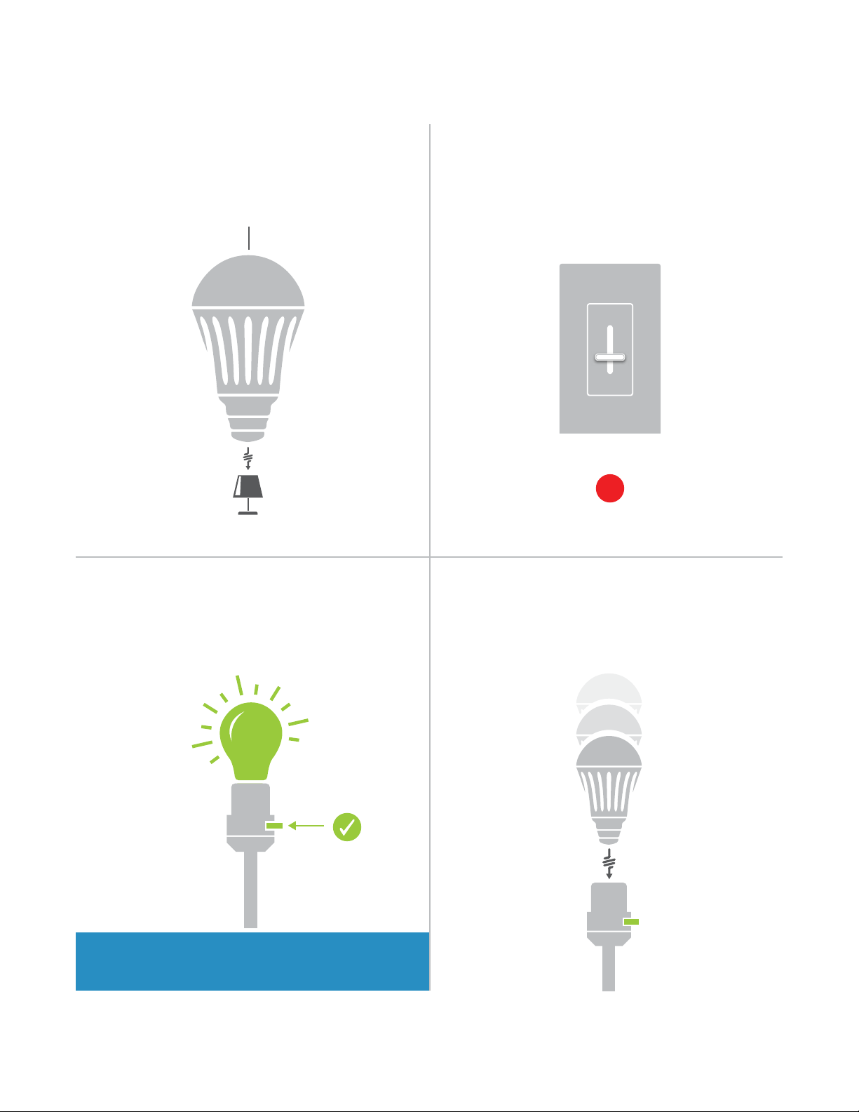
INSTEON LED Bulb
Device Overview Do Not Connect to a Dimmer
INSTEON LED Bulb dims using INSTEON
commands.
INSTEON ID
X
Leave Your Fixture On Linking
If your switch is OFF, communication with the
LED Bulb is lost.
ON
If your xture is controlled by a wall
?
switch, consider wiring as always-on.
Your LED Bulb does not have a set button.
To link manually, unscrew the LED Bulb for a
moment and reinsert.
ON
4
Page 5
INSTEON Links
INSTEON Links
INSTEON devices can stand alone and function as a local switch or
INSTEON devices can stand alone and function as a local switch or
dimmer, but their real power comes when they are connected together to
dimmer, but their real power comes when they are connected together to
form a control system. Most INSTEON devices can control one another
form a control system. Most INSTEON devices can control one another
and be the recipient of control. The process of associating multiple
and be the recipient of control. The process of associating multiple
INSTEON devices to one another is called linking.
INSTEON devices to one another is called linking.
5
Page 6
NEW
NEW
75%
NEW
NEW
Understanding Linking
Links Remember a Device’s StateLinks are One-Way
When linking INSTEON devices, the links that
are created are one-way.
A SwitchB Lamp Dimmer
The current state of the controlled device is
stored in the link: on, o or dimmed.
Switch A will turn Switch B on and o but
Switch B cannot turn Switch A on or o.
INSTEON devices that can turn other devices
on or o are called controllers.
The switch will turn on the Lamp Dimmer to
75% brightness.
RespondersControllers
INSTEON devices that receive the command of a
controller are called responders.
N
On
Neutral
Off
N
Set
Load L1
Line L
Sensors, Switches, Keypads and the
Hub are common controllers.
Switches, Keypads, Plug-In Modules and
In-Line Modules are common responders.
6
Page 7
NEW
NEW
X
Understanding Linking
NEW
NEW
X
Controller-Only
Some devices, like sensors, can only control
other devices.
Motion Sensor
The Motion Sensor will turn on the Switch
but the switch cannot control the Motion
Sensor.
Dimmer Switch
Responder-Only
Some devices cannot control other devices;
these devices only receive INSTEON commands.
LED Bulb Dimmer Switch
Some devices can only link as
responders to devices and scenes.
Grouping Devices Use Cross Linking
You may want to group together two
devices, for example, in a virtual-three way
conguration. For INSTEON, this is called
cross linking.
A BLoad
To mirror Switch A and B so that they each
control one another and the connected
load, Cross Linking is necessary.
To Cross Link, simply turn on the devices and
perform the linking process twice, once in
each direction.
A B
Link Switch A to Switch B and repeat to link
Switch B to Switch A.
7
Page 8
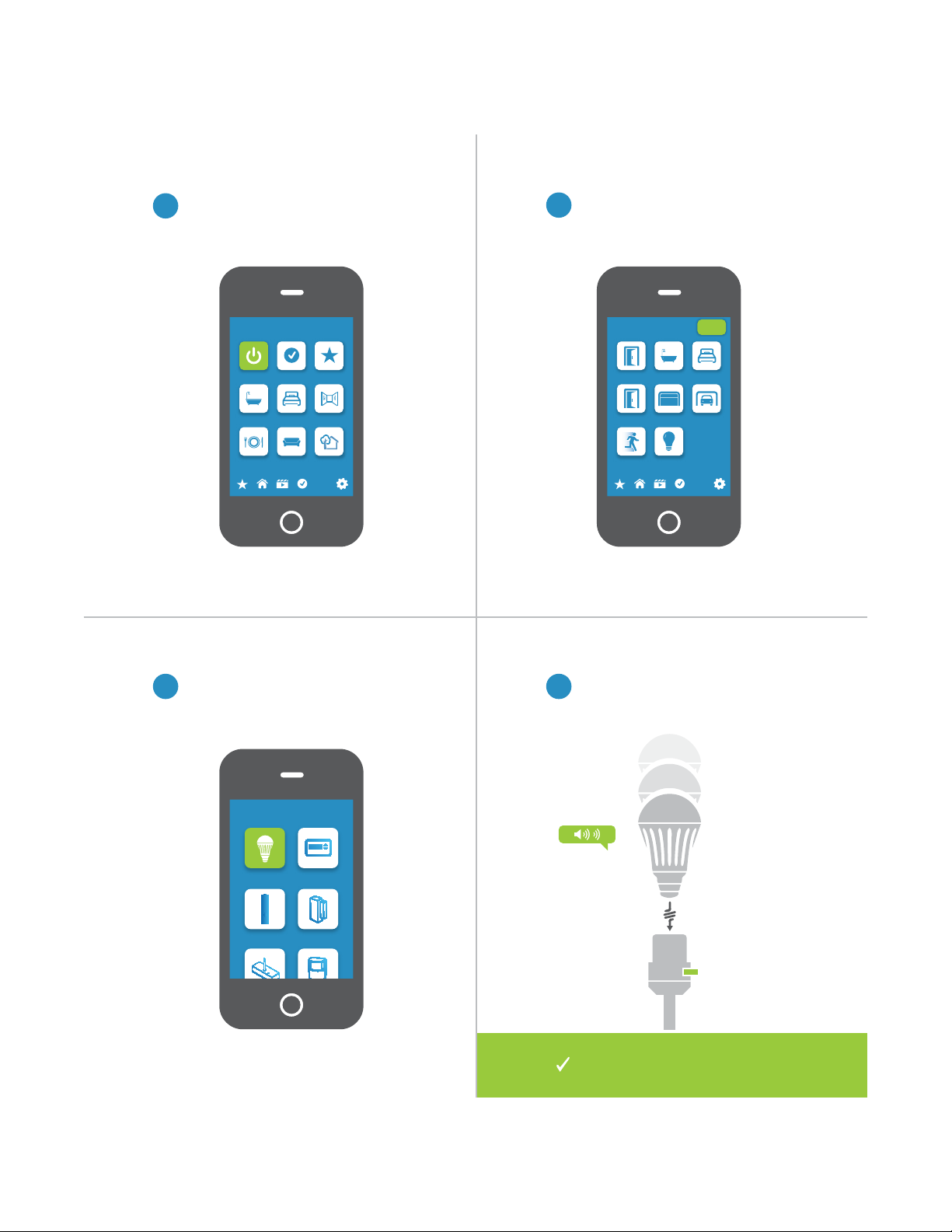
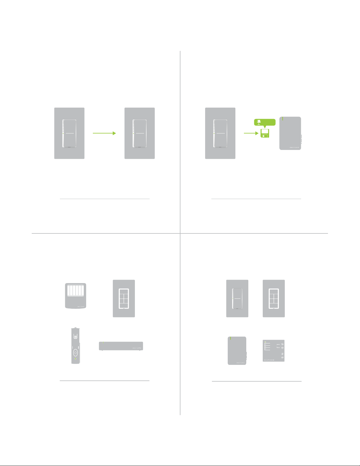
Linking to the INSTEON Hub using the iOS or Android App
From Rooms, navigate to All Devices.
1
Rooms
All Devices Check-In Favorites
Bathroom Bedroom Hallway
Kitchen Living Room Outside
72º
Tap the Add button.
2
Back Door Bathroom Bedroom
Font Door Garage Door Garage Light
Motion Sensor Outside Lights
All Devices
Add
72º
Select LED Bulb from the list of
3 4
devices.
Add Device
LED Bulb Thermostat
Door Sensor
Open/Close
Sensor
When prompted, turn on your xture
and screw in the LED Bulb. The Bulb
will double-beep.
ON
You can now control your LED
Bulb from the INSTEON Hub.
8
Page 9
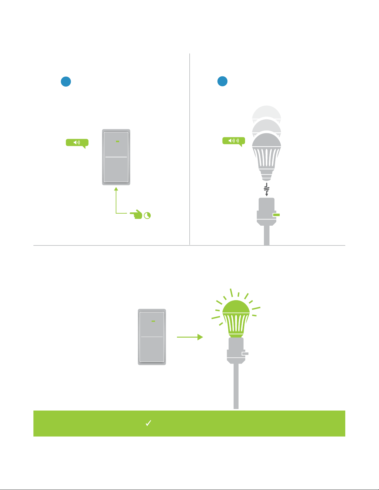
Linking with a Single-Button Controller
On your INSTEON controller, press
1
and hold the set button until the
device beeps.
Make sure your xture is On and
2
then screw in the LED Bulb. Your
LED Bulb will double-beep.
ON
Your INSTEON controller will
now control your LED Bulb.
ON
9
Page 10
Linking with a Multi-Button Controller
On your INSTEON controller, tap
1
the desired control button and
then press and hold the set button
until the device beeps.
B
Make sure your xture is On and
2
then screw in the LED Bulb. Your
LED Bulb will double-beep.
A
ON
Your INSTEON controller will
now control your LED Bulb.
ON
10
Page 11
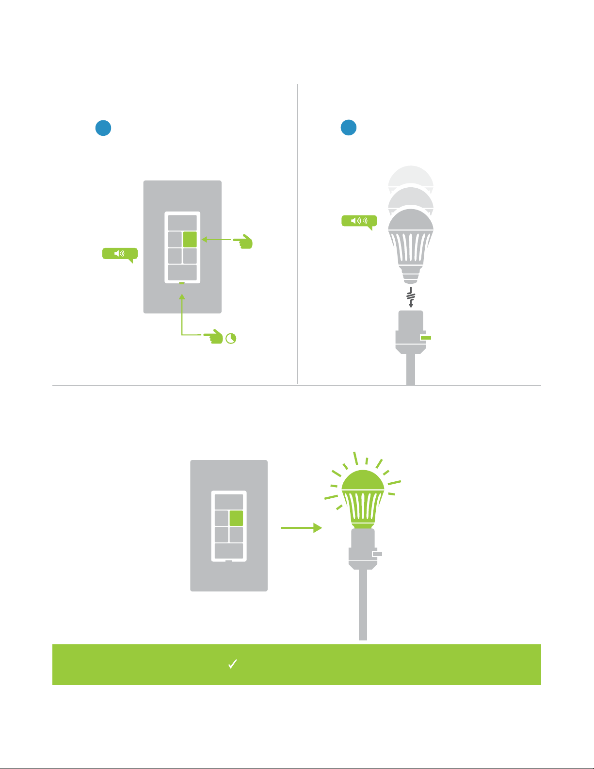
Multi-Linking or Making a Scene
On your INSTEON controller, press
1
and hold the set button until the
device beeps, then tap the set
button.
A
B
Adjust your scene members to
2
their desired state: on, o, or
brightness level if dimming.
50% 72%
LED Bulb
30%
Lamp 3
LED Bulb
ON
Appliance
One at a time, screw in your LED
3 4
Bulbs. For other devices, press
and hold the set button until they
double-beep.
ON
Tap the set button on your
INSTEON controller to nish
building your scene.
Your INSTEON controller will
now control your scene.
11
Page 12
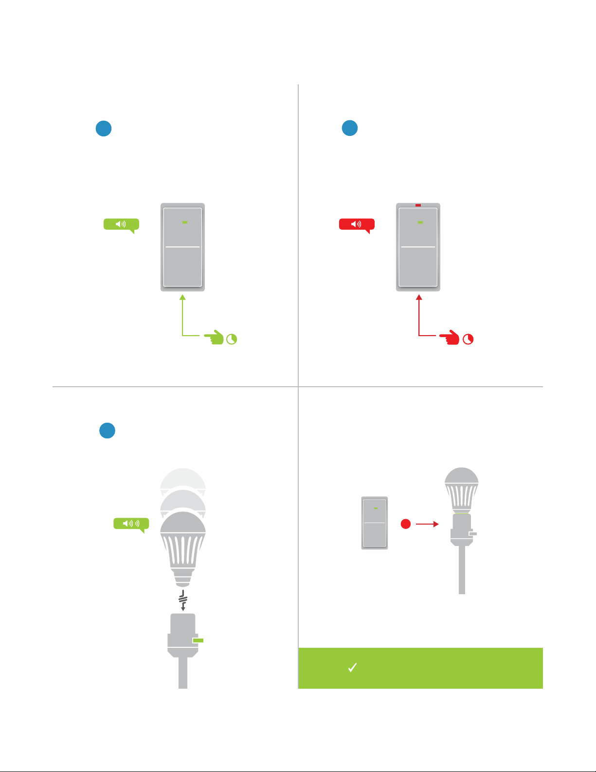
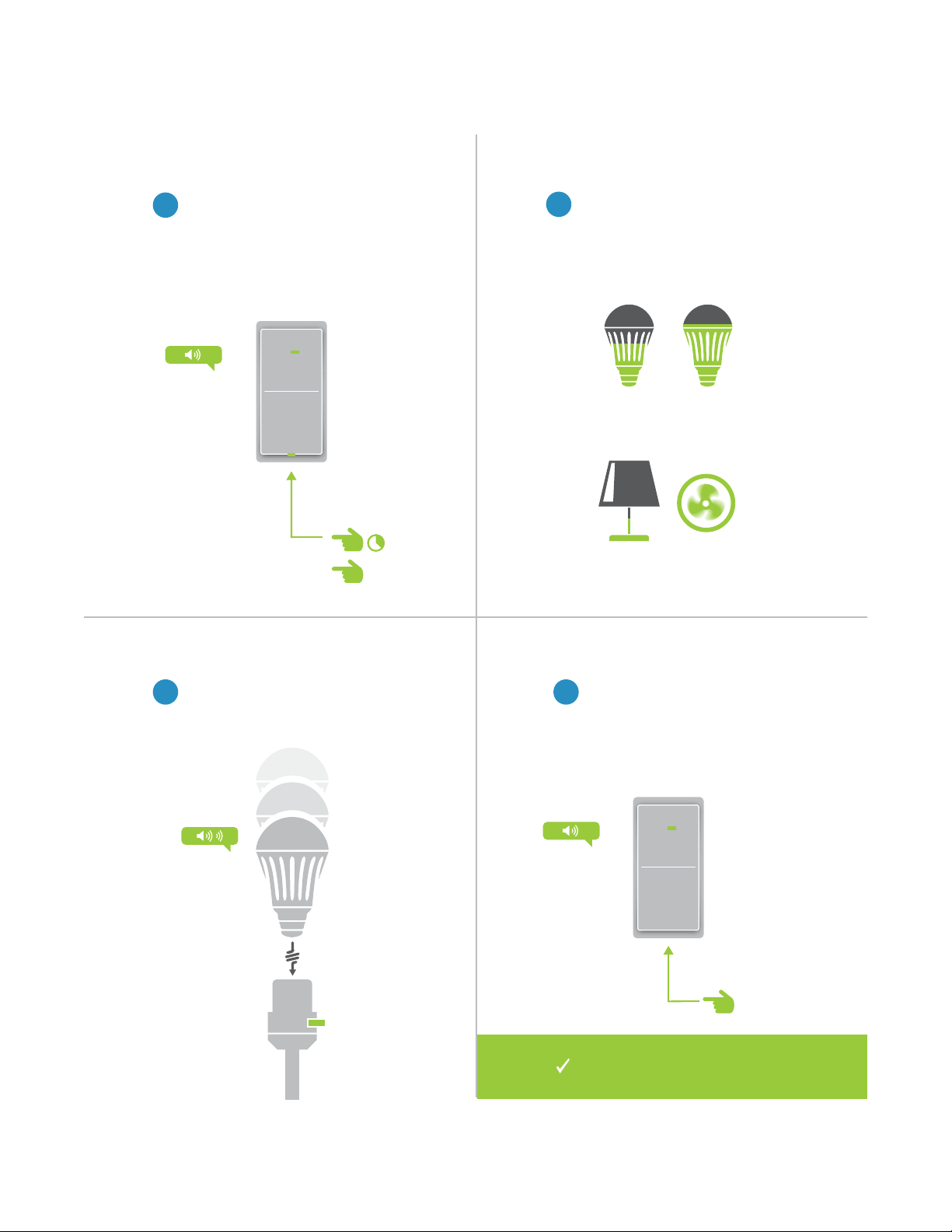
Unlinking from a Single-Button Controller
X
On your INSTEON controller, press
1
and hold the set button until the
device beeps.
Press and hold the set button
2
again until the device beeps.
Make sure your xture is On and
3
then screw in the LED Bulb. Your
LED Bulb will double-beep.
ON
ON
Your INSTEON controller will no
longer control your LED Bulb.
12
Page 13
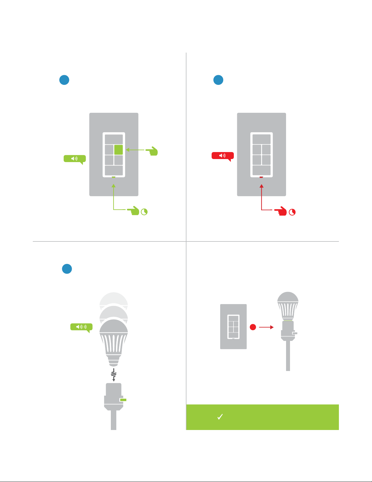
Unlinking from a Multi-Button Controller
X
On your INSTEON controller, tap
1
the desired control button and
then press and hold the set button
until the device beeps.
B
Press and hold the set button
2
again until the device beeps.
A
Make sure your xture is On and
3
then unscrew and reinsert the LED
Bulb. Your LED Bulb will doublebeep.
ON
ON
Your INSTEON controller will no
longer control your LED Bulb.
13
Page 14
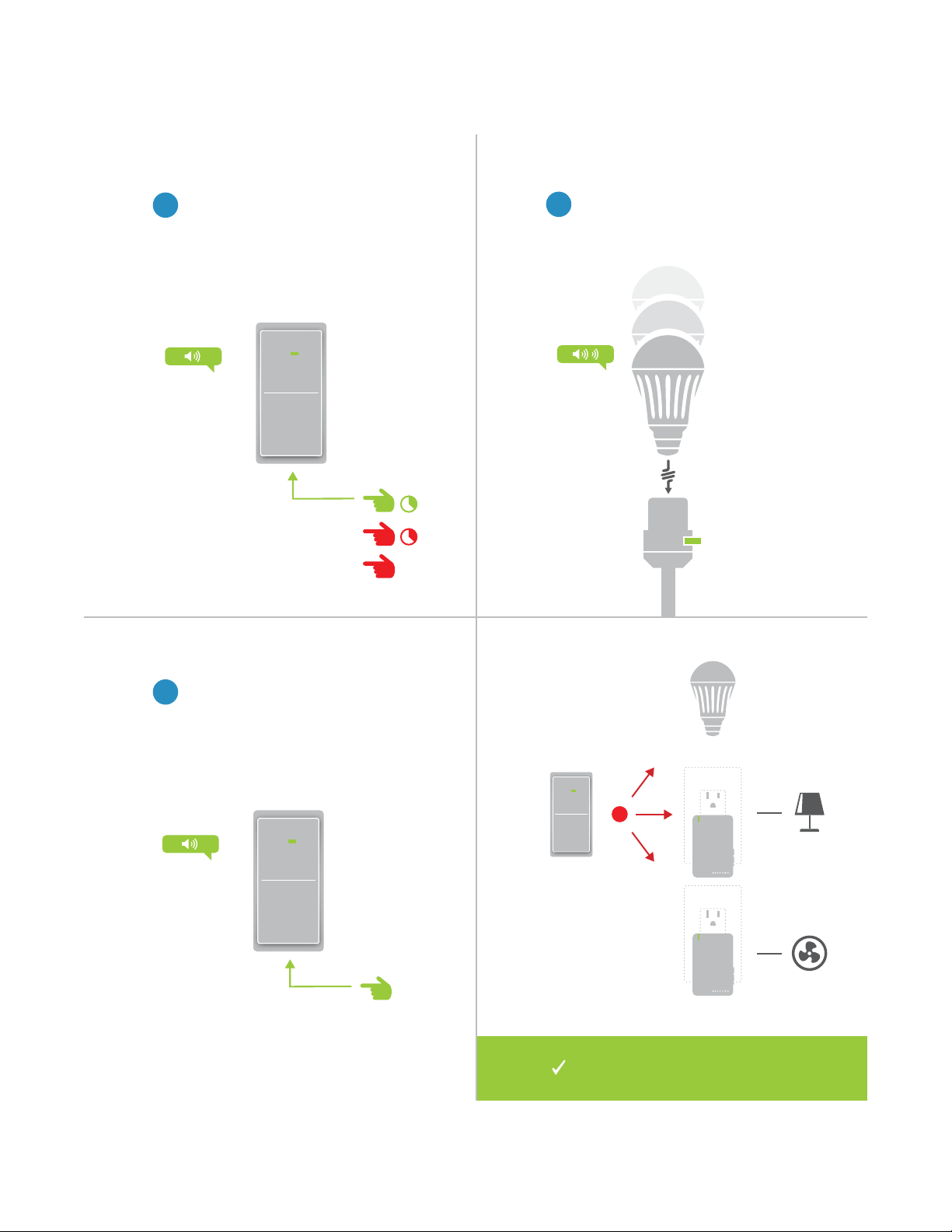
Multi-Unlinking or Removing a Scene
X
On your INSTEON controller, press
1
and hold the set button until the
device beeps. Press and hold the
set button again, then tap the set
button.
One at a time, unscrew and
2
reinsert your LED Bulbs. For other
devices, press and hold the set
button until they double-beep.
A
B
ON
C
Tap the set button on your
3
INSTEON controller to exit Multi-
Unlinking mode.
®
®
Your INSTEON controller will no longer
control your INSTEON devices.
14
Page 15
Software-Only Features
Software-Only Features
Most INSTEON devices contain features that can only be enabled,
Most INSTEON devices contain features that can only be enabled,
disabled or modied using INSTEON control software such as HouseLinc
disabled or modied using INSTEON control software such as HouseLinc
and an INSTEON PowerLine Modem.
and an INSTEON PowerLine Modem.
15
Page 16
Software-Only Features
Ramp Rate Disable Linking on Power-up
Customize the speed at which the LED
Bulb fades on or o. Default is 0.5 seconds,
maximum duration of 8 minutes.
Prevents LED Bulb from entering linking
mode each time power is disconnected and
reapplied. Default is o.
Instant
0.5 Seconds
2 Seconds
5 Seconds
15 Seconds
LINKING
16
Page 17
Always-On Wiring
Always-On Wiring
Because LED Bulb needs constant power, if you have a light xture that is
Because LED Bulb needs constant power, if you have a light xture that is
controlled by a wall switch, you might consider wiring that wall switch as
controlled by a wall switch, you might consider wiring that wall switch as
“Always-On” so that ipping the switch will not disconnect LED Bulb from
“Always-On” so that ipping the switch will not disconnect LED Bulb from
power. Replacing the wall switch with an INSTEON Switch will provide full
power. Replacing the wall switch with an INSTEON Switch will provide full
control for any INSTEON device in your home.
control for any INSTEON device in your home.
17
Page 18
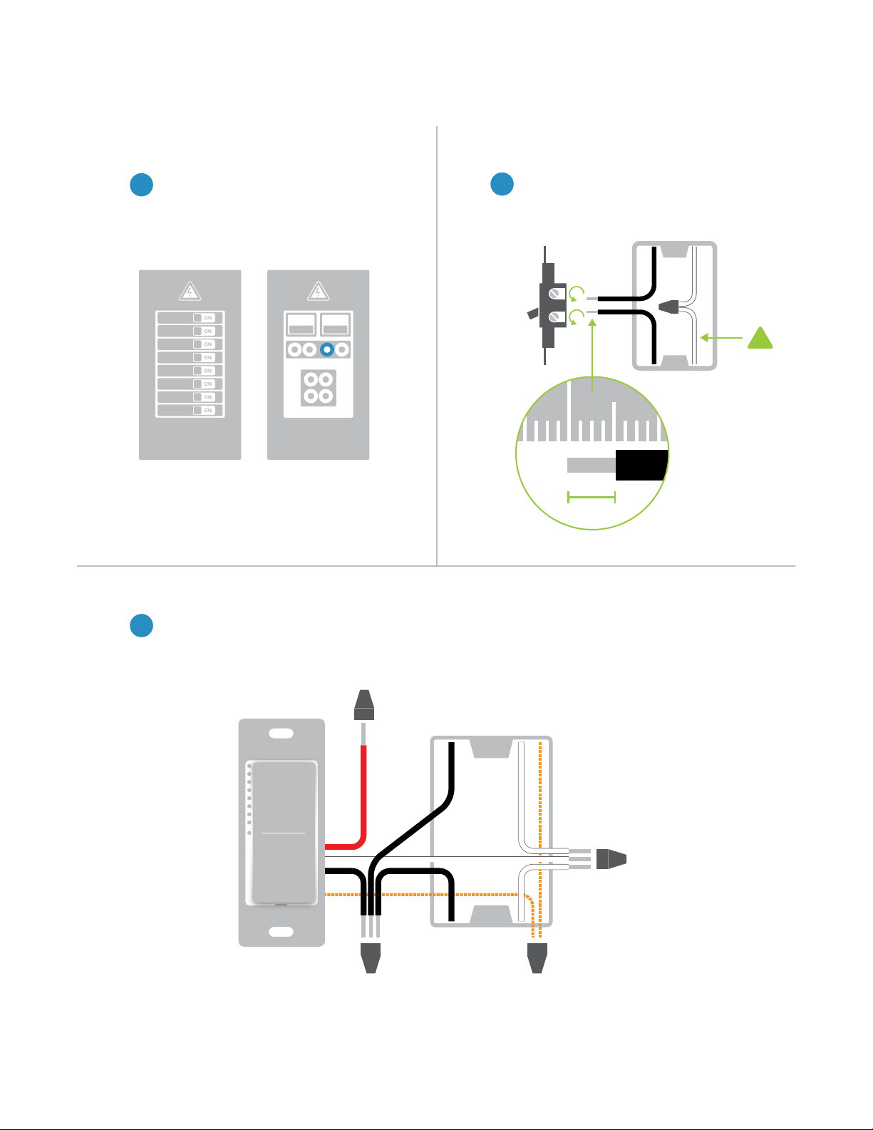
1 2
Always-On Wiring
Turn o power to your switch at the
1
electrical service panel.
ON ON
or
Circuit Breakers Fuse Panel
Remove the old switch and
2
disconnect the wires. If your box
lacks neutral wires, stop and
contact support.
½”
12mm
!
Neutral Wire
3
Connect the Dimmer Switch wires to the identied wires in the junction box. The red load wire is
not used and, instead, capped. Verify that the wire nuts are secure and that no exposed copper
wire is visible except for the bare ground wire.
Load
Neutral
Line
Ground
18
Page 19
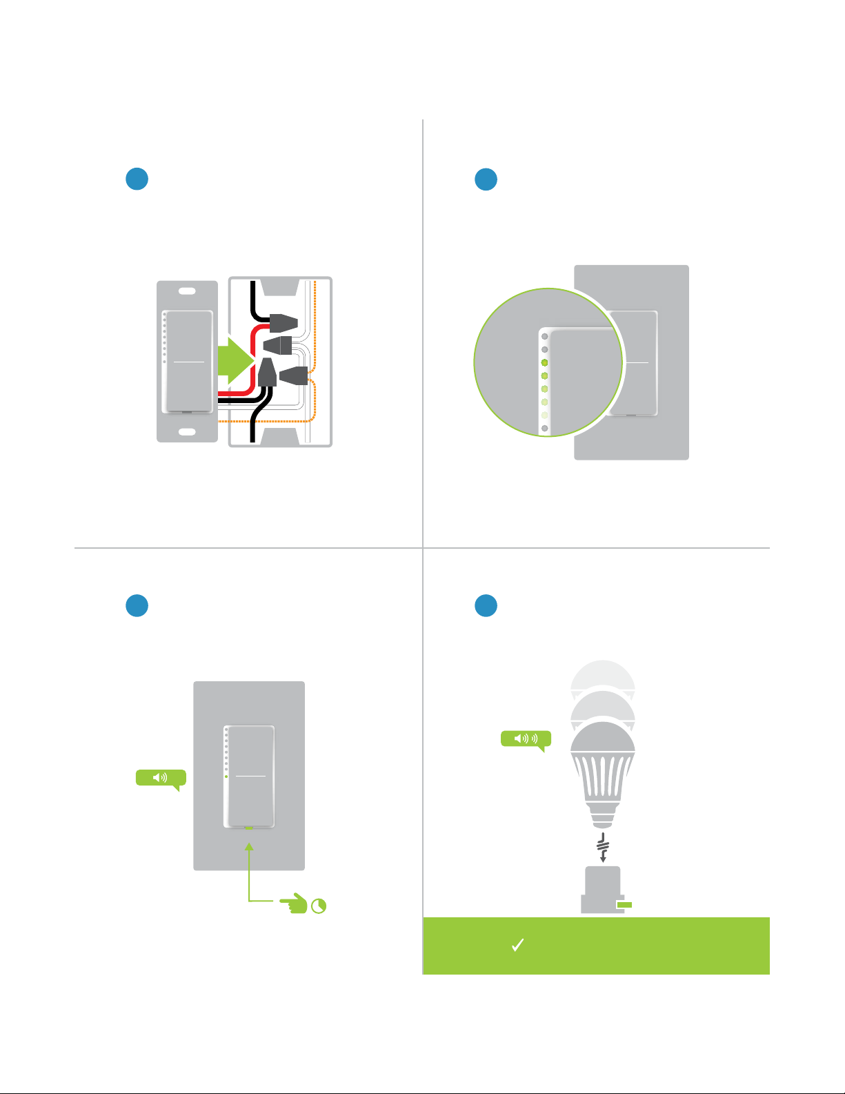
Always-On Wiring
Mount the Dimmer Switch into the
4
junction box with the LED bar on the
left and turn power on to the switch at
the circuit breaker panel.
Test your switch by tapping the paddle
5
to turn On and O. Your LED Bulb will
not change but the status lights on the
switch will.
To link your switch to the LED Bulb,
6 7
press and hold the set button until the
device beeps.
Unscrew and reinsert your LED Bulb
for a moment and reinsert. Your LED
Bulb will double-beep.
ON
Your switch will now control
your LED Bulb
19
Page 20
Appendix
Appendix
Everything else you might need to know about your INSTEON product.
Everything else you might need to know about your INSTEON product.
20
Page 21

INSTEON Glossary
Controller The INSTEON transmitter
Responder The INSTEON receiver
Blinking LED turning on and o repeatedly
Dual-Band An INSTEON device that can send and receive both INSTEON powerline signals and
INSTEON radio frequency signals
Ramp Rate The speed at which the load fades on or o
On-Level The preset brightness level a device will return to when turned on
INSTEON A dual-band, mesh networking technology developed by INSTEON. The world’s most
reliable, expandable and simple home automation and control technology.
Link A one way association between a controller and responder
Linking A method for associating INSTEON controller buttons with groups of INSTEON responders
such that the responders instantly return to a memorized state when the button is pushed.
Links can be made manually with the set button or using software.
Unlinking The process by which an INSTEON device can remove stored links. Just as with linking,
unlinking is a one-way process and should be performed in both directions for devices that
are both controllers and responders of each other, as in a 3-way switch scenario.
Multi-Linking
/ Unlinking
Factory Reset A process that erases all stored links and recongures the device to factory defaults.
Load The device that you are controlling (e.g. a light bulb, ceiling fan, etc.)
On/O A device that can control its connected load to turn on and o but cannot dim. Usually a
Retry A 2nd (or subsequent) attempt by a controller to send an INSTEON signal, usually after an
Scene Multiple devices respond to memorized states. For example, a dinner time scene turns
Set Button A button on an INSTEON device that is used for setting or changing its properties
Simulcast A method for increasing the reliability of message delivery in a network. When a node in
A special mode that allows more than one link to be either created or removed
simultaneously, without laborious set button presses. When in linking or unlinking mode, an
INSTEON device will continue to link to other devices until the set button is tapped or four
minutes have elapsed, whichever occurs rst.
relay-based device.
acknowledge is not received from the responder in the expected time-slot.
on the dining table light, dims the kitchen lights to 10%, backyard lights turn o and the
thermostat adjusts to 72º.
a network sends a message, every other node that hears the message retransmits it at
precisely the same time based on a global clock, provided that the message has not already
been retransmitted some maximum number of times. Message propagation is more robust
because each node adds its energy to the signal, much like voices in a choir. Simulcasting
is much simpler than message routing because there are no routing tables to maintain and
nodes can join the network without any installation procedure.
X10 A legacy powerline networking technology. Many INSTEON devices are backwards
compatible with X10 devices by setting a house and unit code.
21
Page 22

General
INSTEON Features
INSTEON PowerLine Ye s
Specications
Brand INSTEON
Key Application Low energy, remote control lighting
Product Number 2672-222 US
UPC 813922013023
Patent Protected under US and Foreign Patents (see www.insteon.com/
patents)
Warranty 2 years, limited
INSTEON RF Ye s
RF Frequency 915.0 MHz US
INSTEON Controller No
INSTEON Responder Ye s
Number of Responder Groups 400
Responder Commands Supported On O
Fast On Fast O
Begin Brighten Begin Dim
End Brighten End Dim
Incremental Brighten Incremental Dim
Beep
Maximum INSTEON Links 400
X10 Compatible No
Programming Lock Ye s
22
Page 23

Operation
Mechanical
Specications
Lumens 591
Lumens per Watt 66
Color Rendering Index 83.90
Color Temperature 2700 K
Status LED None
On Levels 32
Ramp Rate 0.125 seconds to 8 minutes (software-only)
Installation E27 Medium Edison screw base
Color White
Dimensions 2.8” diameter, 4.7” length
72mm diameter, 119mm length
Weight 6.2 oz
Operating Environment Indoors
Operating Temperature Range -32º to 104º F
Operating Humidity Range 0-90% relative humidity, non-condensing
Electrical
Supply Voltage 120 Volts AC ±10%, 60 Hz
Local Control No
All Settings Saved Through Power
Outage
Power Consumption <0.75 Watt
Certication ETL, FCC
176g
-0º to 40º C
Yes, all saved in non-volatile EEPROM
23
Page 24

Troubleshooting
LED Bulb won’t link to other INSTEON Devices
Your LED Bulb may be out of range of other INSTEON Devices or a large appliance may be generating electrical
noise, disrupting the INSTEON signal.
Try this:
• Check to make sure your LED Bulb is not connected to a dimmer. If so, remove the dimmer or relocate LED
Bulb to a non-dimming xture.
• Try relocating your LED Bulb to see if linking can be accomplished. If linking works normally in another area
of the house, consider adding additional INSTEON devices to extend and strengthen your network.
• Some home appliances like refrigerators, televisions and speaker docks may produce excessive electrical
noise. If you’ve recently added a new electronic device to your home, unplug it and try linking again. If LED
Bulb links normally, add a powerline noise lter to the problematic appliance.
LED Bulb is slow to respond
This issue most likely lies with the controller, not your LED Bulb; the controlling device is probably repeating
commands not being acknowledged by an INSTEON device that has been removed from the network. The
repeated commands are slowing down the INSTEON network, resulting in a delayed response from the LED
Bulb.
Try this:
• Consider if you have removed any INSTEON devices from your network that were part of the slow-torespond scene. If so, the links to these devices need to be removed from the controller. Use software to
examine the database of the controller or if you know the modules that were removed, manually remove
their links using the standard unlinking procedure.
• If you are unable to identify the missing devices, perform a factory reset on the controller. This will remove
all links from the controller’s database but will also require that you recongure the device’s scenes and
properties.
LED Bulb turned on or o by itself
Most likely, a device somewhere in the house has been linked to your LED Bulb.
Try this:
• As LED Bulb automatically enters linking mode every time it is powered on, it is possible to accidentally link
a device to LED Bulb in the brief period of time that the Bulb is in linking mode. You can use software like
HouseLinc to examine LED Bulb’s links to nd the stray connection.
I want to factory reset my LED Bulb
Because LED Bulb lacks a set button, there is no manual way to factory reset LED Bulb.
Try this:
• Using software like HouseLinc, manually remove all of the device links.
24
Page 25

Certications and Warnings
This device complies with Part 15 of the FCC Rules and Industry Canada license-exempt RSS standard(s).
Operation is subject to the following two conditions: (1) this device may not cause interference, and (2) this
device must accept any interference, including interference that may cause undesired operation of the device.
The digital circuitry of this device has been tested and found to comply with the limits for a Class B digital
device, pursuant to Part 15B of the FCC Rules. These limits are designed to provide reasonable protection
against harmful interference in residential installations. This equipment generates, uses, and can radiate
radio frequency energy and, if not installed and used in accordance with the instructions, may cause harmful
interference to radio and television reception. However, there is no guarantee that interference will not occur in
a particular installation. If this device does cause such interference, which can be veried by turning the device
o and on, the user is encouraged to eliminate the interference by one or more of the following measures: •
Re-orient or relocate the receiving antenna of the device experiencing the interference • Increase the distance
between this device and the receiver • Connect the device to an AC outlet on a circuit dierent from the one that
supplies power to the receiver • Consult the dealer or an experienced radio/TV technician.
WARNING: Changes or modications to this device not expressly approved by the party responsible for
compliance could void the user’s authority to operate the equipment.
CAUTION - To reduce the risk of overheating and possible damage to other equipment do not install to control
a receptacle, a motor-operated appliance, a uorescent lighting xture, or a transformer-supplied appliance.
Gradateurs commandant une lampe a lament de tungstene – an de reduire le risqué de surchaue et la
possibilite d’endommagement a d’autres materiels, ne pas installer pour commader une prise, un appareil a
moteur, une lampe uorescente ou un appareil alimente par un transformateur.
Le présent appareil est conforme à l’article 15C des règlements de la FCC et CNR d’Industrie Canada
applicables aux appareils radio exempts de licence. L’exploitation est autorisée aux deux conditions
suivantes : (1) l’appareil ne doit pas produire de brouillage, et (2) l’utilisateur de l’appareil doit accepter tout
brouillage radioélectrique subi, même si le brouillage est susceptible d’en compromettre le fonctionnement.
Cet appareil a été testé et s’avère conforme aux restrictions relatives aux équipements numériques de classe B,
d’après l’article 15 des règlements du Conseil supérieur de l’audiovisuel américain (FCC). Ces restrictions ont
été instaurées pour orir une protection raisonnable contre les interférences nuisibles au sein d’une installation
résidentielle. Cet appareil génère, utilise et peut émettre des fréquences radio et s’il n’est pas installé selon les
instructions, peut nuire aux radiocommunications. Toutefois, rien ne garantit que des parasites ne surviendront
pas dans une installation particulière. Si cet appareil cause des interférences nuisibles à la réception du
téléviseur ou de la radio, ce que vous pouvez déterminer en ouvrant et en fermant votre appareil, nous vous
invitons à essayer l’une des mesures correctives suivantes : • Réorientez l’antenne de réception installée sur
l’appareil qui manifeste les parasites.
• Éloignez l’appareil du composant qui reçoit les ondes. • Branchez l’appareil dans une prise de courant CA
diérente de celle du composant qui reçoit les ondes. • Au besoin, consultez votre marchand électronique ou un
technicien spécialisé dans le service des radios/téléviseurs pour des suggestions supplémentaires.
25
Page 26

Product Warranty
Limited Warranty
Seller warrants to the original consumer purchaser of this product that, for a period of two years from the date
of purchase, this product will be free from defects in material and workmanship and will perform in substantial
conformity to the description of the product in this Owner’s Manual. This warranty shall not apply to defects or
errors caused by misuse or neglect. If the product is found to be defective in material or workmanship, or if the
product does not perform as warranted above during the warranty period, Seller will either repair it, replace it,
or refund the purchase price, at its option, upon receipt of the product at the address below, postage prepaid,
with proof of the date of purchase and an explanation of the defect or error. The repair, replacement, or refund
that is provided for above shall be the full extent of Seller’s liability with respect to this product. For repair or
replacement during the warranty period, call 866-243-8022 with the Model # and Revision # of the device to
receive an RMA# and send the product, along with all other required materials to:
INSTEON
ATTN: Receiving
16542 Millikan Ave.
Irvine, CA 92606-5027
Limitations
The above warranty is in lieu of and Seller disclaims all other warranties, whether oral or written, express or
implied, including any warranty or merchantability or tness for a particular purpose. Any implied warranty,
including any warranty of merchantability or tness for a particular purpose, which may not be disclaimed
or supplanted as provided above shall be limited to the two-year of the express warranty above. No other
representation or claim of any nature by any person shall be binding upon Seller or modify the terms of the
above warranty and disclaimer.
Home automation devices have the risk of failure to operate, incorrect operation, or electrical or mechanical
tampering. For optimal use, manually verify the device state. Any home automation device should be viewed as
a convenience, but not as a sole method for controlling your home.
In no event shall Seller be liable for special, incidental, consequential, or other damages resulting from
possession or use of this device, including without limitation damage to property and, to the extent permitted by
law, personal injury, even if Seller knew or should have known of the possibility of such damages. Some states
do not allow limitations on how long an implied warranty lasts and/or the exclusion or limitation of damages, in
which case the above limitations and/or exclusions may not apply to you. You may also have other legal rights
that may vary from state to state.
Protected under U.S. and foreign patents (see www.insteon.com/patents)
© Copyright 2013 INSTEON
Rev 06.10.14
26
 Loading...