

Page 1
Dimmer Module
2632-442
(UK)
2632-522
(Aus/NZ)
2632-422
(France)
2632-432
Owner’s Manual
2632-422 (France)
2632-432 (Germany)
2632-442 (UK)
2632-452 (Chile)
2632-522 (AUS/NZ)
(Germany)
2632-452 (Chile)
Page 1 of 16 2632-422/2632-432/2632-442/2632-522 - Rev: 1/21/2014 7:46 AM
Page 2

LED
Paddle top
Paddle bottom
(off/dim)
Set button
About Dimmer Module .................................................................................................................................................. 2
Features and Benefits.................................................................................................................................................. 3
Installation ..................................................................................................................................................................... 3
TRIAC Dimming Technology ....................................................................................................................................... 3
Using Dimmer Module Paddle ..................................................................................................................................... 4
Adjust Local Settings.................................................................................................................................................... 4
Local On-Level ............................................................................................................................................................. 4
Local Ramp Rate ......................................................................................................................................................... 4
Resume Dim ................................................................................................................................................................ 5
Change LED Brightness (or turn it off) ........................................................................................................................ 6
Error Blink .................................................................................................................................................................... 6
Blink on Traffic ............................................................................................................................................................. 6
Beep on Button Press .................................................................................................................................................. 6
INSTEON Setup ............................................................................................................................................................. 6
INSTEON Controllers, Responders and Links ............................................................................................................ 6
Configure INSTEON Settings ...................................................................................................................................... 7
Make Dimmer Module a Responder ............................................................................................................................ 7
Make Dimmer Module a Controller .............................................................................................................................. 7
Groups ......................................................................................................................................................................... 8
Scenes ......................................................................................................................................................................... 8
Make Dimmer Module a Controller of Multiple Responders ........................................................................................ 8
Remove Dimmer Module as a Controller .................................................................................................................... 9
Remove Dimmer Module as a Responder .................................................................................................................. 9
Remove Dimmer Module as a Controller of Multiple Responders .............................................................................. 9
Factory Reset .............................................................................................................................................................. 9
X10 Setup ..................................................................................................................................................................... 10
Add X10 Address ....................................................................................................................................................... 10
Remove X10 Address ................................................................................................................................................ 10
Specifications .............................................................................................................................................................. 10
Troubleshooting .......................................................................................................................................................... 13
Phase Bridge Detect Beacon/RF Range Test ........................................................................................................... 15
Certification and Warranty ......................................................................................................................................... 15
Declaration of Conformity .......................................................................................................................................... 15
About Dimmer Module
INSTEON Dimmer Module makes adding customizable, fully dimmable INSTEON (and X10) remote control to your
lamps as easy as plug and play. It’s home automation at its simplest and most convenient.
Page 2 of 16 2632-422/2632-432/2632-442/2632-522 - Rev: 1/21/2014 7:46 AM
(on/brighten)
Page 3
electrical circuitry, you should have a qualified electrician install the product for you.
Features and Benefits
• Integrated dimmer with 32 brightness levels and 32 ramp rates
• Compatible with all INSTEON (and X10) controllers; can also act as an INSTEON (and X10) controller
• Super-easy setup with multi-color LED and beeper
• Dual-band communicates simultaneously over both RF and powerline
• Stores setup state in non-volatile memory so settings aren’t lost during power outages
• Two-year warranty
Installation
CAUTIONS AND WARNINGS
Read and understand these instructions before installing and retain them for future reference.
This product is not designed or approved for use on powerlines other than 100-240VAC,50Hz or 60Hz, single phase. Attempting to use this
product on non-approved powerlines may have hazardous consequences.
- Use only indoors or in outdoor rated box
- This product may feel warm during operation. The amount of heat generated is within approved limits and poses no hazards. To
minimize heat buildup, ensure the area surrounding this product is as clear of clutter as possible.
- Each INSTEON product is assigned a unique INSTEON I.D., which is printed on the product’s label.
- To reduce the risk of overheating and possible damage to other equipment, do not use this product to control loads in excess of the
specified maximum(s) or, install in locations with electricity specifications which are outsi de of the product’s specifications. If this device
supports dimming, please note that dimming an inductive load, such as a fan or transformer, could cause damage to the dimmer, the
load bearing device, or both. If the manufacturer of the load device does not recommend dimming, use a non-dimming INSTEON on/off
switch. USER ASSUMES ALL RISKS ASSOCIATED WITH DIMMING AN INDUCTIVE LOAD.
IMPORTANT! If you have any difficulties or questions, consult an electrician. If you are not knowledgeable about, and comfortable with,
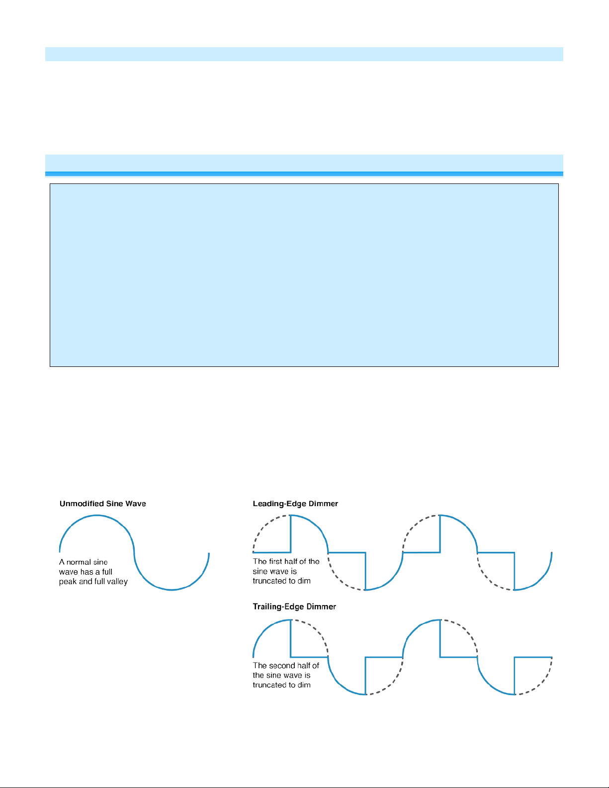
TRIAC Dimming Technology
INSTEON dimming modules utilize a leading-edge TRIAC dimmer that modifies the first half of the AC wavef orm.
This type of dimmer is compatible with resistive and inductive loads but not capacitive loads.
Some low-voltage lights with AC transformers are not compatible with the type of dimmer used in INSTEON dimming
modules. Connecting a capacitive load to a TRIAC dimmer can damage both the lamp and the dimmer circuitry. If
your lamp requires a trailing-edge dimmer, do not connect it to an INSTEON dimming module. Instead, use an
INSTEON On/Off module.
Page 3 of 16 2632-422/2632-432/2632-442/2632-522 - Rev: 1/21/2014 7:46 AM
Page 4
In the Box
Tools Needed
Optional Accessories
Dimmer Module
None
INSTEON Hub
Quick Start Guide
Mini Remote
Dimmer Module Paddle
Tap
Press and hold
Double-tap
LED
1) Turn on lamp
2) Unplug lamp and plug it into Dimmer Module receptacle
3) Plug Dimmer Module into unswitched wall outlet
Lamp will turn on
Dimmer Module LED will turn green
Using Dimmer Module Paddl e
Dimmer Module’s paddle will control the load and any additional linked responders with tap, double-tap and press and hold
actions to initiate different behaviors.
Top
Bottom
On
ramp to preset on-level
Off
ramp to off
Brighten
until release or 100%
Dim
until release or of f
Instant full-on Green
Instant full-off Red
Adjust Local Settings
Local On-Level
The local on-level is the brightness at which the connected load will come on when turned on at the local paddle. The
default on-level is 100% brightness, but it can be set to any one of 32 fixed brightness levels (3% to 100%) or
“resume dim” (brightness prior to last being turned off).
1) Press and hold Dimmer Module set button until it beeps
LED will start blinking gree n
2) Press and hold Dimmer Module set button until it beeps a second time
LED will start blinking red
3) Press and hold Dimmer Module set button until it beeps a third time
LED will start blinking gree n
4) Press and hold Dimmer Module set button until it beeps a fourth time
LED will start blinking red
5) Tap Dimmer Module set button
LED will start double-blinking red
6) Use Dimmer Module’s paddle to adjust lamp to desired brightness desired when turned on at paddle (or turn off
to enable resume bright)
7) Press and hold Dimmer Module set button to accept
Dimmer Module will double-beep and the LED will stop blinking
8) Test by turning lamp off and then back on via Dimmer Module paddle
Light will turn on at new local on-level
Local Ramp Rate
The local ramp rate is the time it takes for the connected light to reach 100% brightness from full-off. The default local
ramp rate is 0.5 seconds, but it can be adjusted from instant-on to 5 seconds (using set button) or up to 8 minutes
(with software).
Page 4 of 16 2632-422/2632-432/2632-442/2632-522 - Rev: 1/21/2014 7:46 AM
Page 5

Ramp Rate Presets
0.5 seconds
2 seconds
Note: If your local on-level is set to a brightness level that is less than 100%, the ramp rate will be faster than
programmed. For example, if your light has a 50% local on-level and a ramp rate of 2 seconds, it will take 1 second
for it to ramp from full-off to the local on-level.
1) Press and hold Dimmer Module set button until it beeps
LED will start blinking green
2) Press and hold Dimmer Module set button until it beeps a second time
LED will start blinking red
3) Press and hold Dimmer Module set button until it beeps a third time
LED will start blinking green
4) Press and hold Dimmer Module set button until it beeps a fourth time
LED will start blinking red
5) Slowly tap set button 2 times
LED will continue blinking red
6) Press and hold Dimmer Module set button to see the next available ramp rate
Load will ramp from off to on at the next available ramp rate
LED will continue blinking red
7) If this is the desired ramp rate, tap Dimmer Module set button to accept
Dimmer Module will double-beep and the LED will stop blinking
8) To see the next ramp rate, press and hold Dimmer Module set button again
Load will ramp from off to on at the next available ramp rate
“Instant”
(factory default)
5 seconds
9) Test by turning off and then back on via the local switch
Light will ramp off and back on at the new local ramp rate
Resume Dim
When resume dim is enabled, each time you turn on Dimmer Module it will go to the previously used dim level. By
default, Dimmer Module will come on at 100% brightness, but to change the desired level, simply follow the
instructions below. The next time you turn Dimmer Module off and on again, it will return to the last used dim level.
1) Press and hold Dimmer Module set button until it beeps
LED will start blinking gree n
2) Press and hold Dimmer Module set button until it beeps a second time
LED will start blinking red
3) Press and hold Dimmer Module set button until it beeps a third time
LED will start blinking gree n
4) Press and hold Dimmer Module set button until it beeps a fourth time
LED will start blinking red
5) Slowly tap Dimmer Module set button three times
LED will start double-blinking red
6) Press and hold Dimmer Module set button until it double-beeps
LED will stop blinking
Page 5 of 16 2632-422/2632-432/2632-442/2632-522 - Rev: 1/21/2014 7:46 AM
Page 6

7) Test by turning off and then back on via the local switch
Light will ramp off and back on at resume dim level
Change LED Brightness (or turn it off)
Default = 50% brightness level
1) Press and hold Dimmer Module set button until it beeps
LED will start blinking green
2) Press and hold Dimmer Module set button until it beeps a second time
LED will start blinking red
3) Press and hold Dimmer Module set button until it beeps a third time
LED will start blinking green
4) Tap Dimmer Module set button once
LED starts double-blinking green
5) Press and hold Dimmer Module set button until it beeps
LED will turn green (at brightness of connected load)
6) Use the Dimmer Module’s paddle to brighten or dim LED to desired brightness
7) Tap Dimmer Module set button to accept
Dimmer Module will double-beep and return to rea dy mode
Error Blink
Default = enabled
This setting is only adjustable via software or a central controller. Dimmer Module LED will blink red once if one or
more responders do not acknowledge a message and will blink green once if all responders are successful.
Blink on Traffic
Default = disabled
This setting is only adjustable via software or a central controller. Dimmer Module LED will blink red if it detects noise
that could disrupt communication.
Beep on Button Press
Default = disabled
This setting is only adjustable via software or a central controller. Dimmer Module will beep every time its paddle is
tapped.
INSTEON Setup
Some products have subtle differences in their setup procedures. Please refer to the other devices’ owner’s manuals
for details.
INSTEON Controller s, R es pon der s and Li nk s
Let’s define a few terms.
• The INSTEON “transmitter” is called a controller
• The INSTEON “receiver” is called a responder
• The association between the controller and responder is called a link
Page 6 of 16 2632-422/2632-432/2632-442/2632-522 - Rev: 1/21/2014 7:46 AM
Page 7

Controller
Responder
Link
Note that a link is one way. If you wish to have control “the other way,” simply add a link “the other way.”
Configure INSTEON Settings
Most Dimmer Module links and settings can be configured locally—during installation with the module’s set button or
after installation using the switch connected to the module—or remotely via software (sold separately).
All Dimmer Module settings can be managed remotely via software (sold separately).
Make Dimmer Module a Responder
1) Press and hold controller set button until it beeps
Controller LED will start blinking green
You will have four minutes to complete the next steps before linking mode times out
2) Turn on lamp connected to Dimmer Module and adjust to desired brightness level
3) Press and hold Dimmer Module set button until it double-beeps
Controller will double-beep and its LED will stop blinking
4) Test link by tapping controller button on and off or pressing and holding to brighten/dim
Lamp connected to Dimmer Module will respond appropriately
Note:
- The link just created is one way. See Make Dimmer Module a Controller or Groups
keep the two products in sync.
- If you wish the load to be off when link is activated—such as for an “all off” scene—turn off the load in step
#2.
to add another link to
Make Dimmer Module a Controller
1) Press and hold Dimmer Module set button until it beeps
Dimmer Module LED will start blinking green
You will have four minutes to complete the next steps before linking mode times out
2) Adjust responder to desired state
3) Press and hold responder set button until it double-beeps
Dimmer Module will double-beep and its LED will stop blinking
4) Test link by tapping or pressing and holding Dimmer Module paddle to turn on/off or brighten/dim
Responder will respond appropriately
Note:
- The link just created is one way. See Make Dimmer Module a Responder or Groups
keep the two products in sync.
- If you wish the load to be off when link is activated—such as for an “all off” scene—turn off the load in step
#2.
1
If either controller or responder LED continues blinking, the addition failed. Tap device’s set button until LED stops blinking and try linking again.
Page 7 of 16 2632-422/2632-432/2632-442/2632-522 - Rev: 1/21/2014 7:46 AM
1
to add another link to
Page 8

Groups
Devices in a group share all the same settings (e.g., on-level, ramp rate). This keeps all group members
synchronized. Every device in a group is both a controller of, and responder to, all the other devices. The most
common example of a group is a 3-way lighting circuit (2 switches). For simplicity, we will assume that the desired
group level is on.
The following steps will create a virtual 3-way circuit including device “A” and device “B”:
1) Turn A and B on
2) Press and hold A set button until it beeps
A status LED will start blinking green
3) Press and hold B set button until it double-beeps
A will double-beep and its LED will stop blinking
4) Press and hold B set button until it beeps
B LED will start blinking green
5) Press and hold A set button until it double-beeps
B will double-beep and its LED will stop blinking
6) Test by turning load on and off from A and then B
The load(s) and both A and B LEDs will remain in synch
Scenes
Devices in a scene can each have different settings. This provides for advanced scene creation. Software is
recommended for scene management.
Example of a scene with 1 controller and Dimmer Module as a member:
1) Press and hold controller set button until it beeps
Controller LED will start blinking green
2) Tap controller set button
Controller LED will start double-blinking green
3) Adjust Dimmer Module to desired brightness level
4) Press and hold Dimmer Module set button until it double-beeps
5) For each additional scene member:
a) Adjust member to desired scene brightness
b) Press and hold set button until it double-beeps
6) Tap controller set button
Controller will beep and LED will stop blinking
7) Test by tapping controller button on and off
Dimmer Module and other scene respon der s will all res pond appropriately
Make Dimmer Module a Controller of Multiple Responders
1) Press and hold Dimmer Module set button until it beeps
LED will start blinking green
2) Tap Dimmer Module set button
LED will start double-blinking green
3) For each responder you are adding:
a) Adjust responder to desired scene brightness/state
b) Press and hold set button until it double-beeps
4) Tap Dimmer Module set button
Dimmer Module will beep and LED will stop blinking
5) Test by tapping Dimmer Module paddle on and off
All the responders will turn on and off
Page 8 of 16 2632-422/2632-432/2632-442/2632-522 - Rev: 1/21/2014 7:46 AM
Page 9

Remove Dimmer Module as a Controller
If you no longer want Dimmer Module to control another device (or are removing Dimmer Module from your network)
it is important that you follow the instructions below for each responder.
1) Press and hold Dimmer Module set button until it beeps
LED will start blinking gree n
2) Press and hold Dimmer Module set button until it beeps a second time
LED will start blinking red
3) Press and hold responder set button until it double-beeps
Dimmer Module will double-beep and LED will stop blinking
4) Test by tapping Dimmer Module on and off
Former responder will not respond
Remove Dimmer Module as a Responder
If you no longer want a controller button to control Dimmer Module, follow these directions.
Note: If you ever wish to uninstall Dimmer Module, it is important that you remove all Dimmer Module responder
links. Otherwise, controllers will repetitively retry commands, creating network delays.
1) Press and hold controller button until it beeps
LED will start blinking green
2) Press and hold controller button until it beeps a second time
LED will start blinking red
3) Press and hold Dimmer Module set button until it double-beeps
Controller LED will stop blinking
4) Test by tapping controller button on and off
Dimmer Module will no longer respon d
Remove Dimmer Module as a Controller of Multiple Responders
1) Press and hold Dimmer Module set button until it beeps
LED will start blinking green
2) Press and hold Dimmer Module set button until it beeps a second time
LED will start blinking red
3) Tap Dimmer Module set button
LED will start double-blinking red
4) For each responder you are removing:
a. Press and hold set button until it double-beeps
5) Tap Dimmer Module set button
Dimmer Module will beep and LED will stop blinking
6) Test by tapping Dimmer Module paddle on and off
None of the former responders will respond
Factory Reset
All settings, link s and scenes will be erased.
1) Press and hold Dimmer Module set button until it beeps
LED will start blinking gree n
2) Press and hold Dimmer Module set button until it beeps a second time
LED will start blinking red
3) Press and hold Dimmer Module set button until it beeps a third time
LED will start blinki ng gr ee n
4) Slowly tap Dimmer Module set button three times
LED will start double-blinking green
5) Press and hold Dimmer Module set button. Do not let go.
Dimmer Module will begin to emit a long beep
Page 9 of 16 2632-422/2632-432/2632-442/2632-522 - Rev: 1/21/2014 7:46 AM
Page 10

General
Product name
Dimmer Module
Brand/manufacturer
INSTEON
Warranty
2 years, limited
INSTEON
INSTEON powerline mesh repeater
Yes
6) After beep stops, release Dimmer Module set button
After a few seconds, Dimmer Module will double-beep
X10 Setup
Dimmer Module ships w ith no X10 addres s ass igned.
Add X10 Address
1) Press and hold set button until it beeps
LED will start blinking green
2) Send the X10 address 3 times (with or without commands)
Example: A1-AON-A1-AON-A1-AON or A1-A1-A1-AON
Dimmer Module will double-beep and LED will stop blinking
3) Test by sending X10 on and off commands
Lamp will turn on and off
Remove X10 Address
1) Press and hold set button until it beeps
LED will start blinking green
2) Press and hold set button until it beeps a second time
LED will start blinking red
3) Send the X10 address 3 times (with or without commands)
Example: A1-OFF-A1-OFF-A1-OFF or A1-A1-A1-AOFF
Dimmer Module will double-beep and LED will stop blinking
4) Test by sending X10 on and off commands
Dimmer Module will not respond
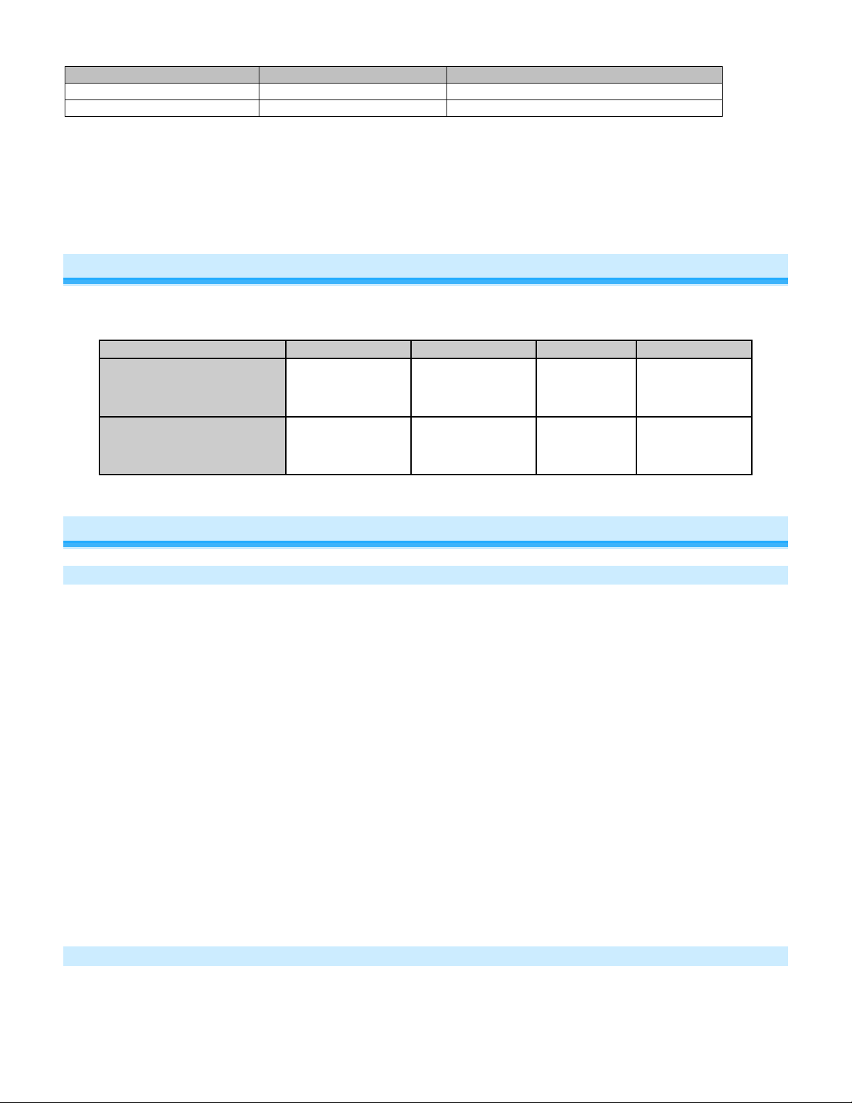
Specifications
Manufacturer product number
UPC
France 2632-422
Germany 2632-432
UK 2632-442
Chile 2632-452
AUS/NZ 2632-522
France 813922012613
Germany 813922012620
UK 813922012637
Chile 813922014105
AUS/NZ 813922012644
Page 10 of 16 2632-422/2632-432/2632-442/2632-522 - Rev: 1/21/2014 7:46 AM
Page 11

INSTEON RF mesh repeater
Yes
INSTEON controller
Yes
INSTEON responder
Yes
Maximum links/scenes
400
Load brightness levels
32 when controlled locally (256 remotely)
LED
Green when load is on, red when load is off
Blinks green once when all responders acknowledge (can be
Blinks red or green during setup
Blinks red to indicate traffic (must be enabled via software)
Beep on button press
Beeps when button is pressed (must be enabled via software)
LED brightness
Adjustable, from off to bright
Local on-level
Adjustable, 32 fixed brightness levels or resume dim
Adjustable from 0.1 seconds to 5 seconds locally
Local control
Yes
On
Off
Fast-on
Fast-off
Begin brighten
Begin dim
End brighten
End dim
On
Off
Fast-on
Fast-off
Begin brighten
Begin dim
End brighten
End dim
Incremental brighten
Incremental dim
Beep
Software configurable
Yes
RF range
Up to 50 meters (150 feet) open air
Phase bridge detect beac o n
Yes
2632-422 (France, 869.85 MHz)
0x0B
2632-432 (Germany, 869.85 MHz)
0x0F
2632-442 (UK, 869.85 MHz)
0x11
2632-452 (Chile, 915.0 MHz)
0x50
2632-522 (Aus/NZ, 921.0 MHz)
0x12
X10
X10 address
1 optional (comes unassigned)
X10 transmitter
Yes
X10 receiver
Yes
X10 status response
Supported
disabled via software)
Blinks red once if responder does not acknowledge
Local ramp-rate
Commands supported as controller
Commands supported as responder
INSTEON device category
(0.1 seconds to 8 minutes via software)
0x01 dimmable lighting control
INSTEON device subcategory
Page 11 of 16 2632-422/2632-432/2632-442/2632-522 - Rev: 1/21/2014 7:46 AM
Page 12

X10 resume dim
Supported (by setting local on-level to zero)
X10 minimum transmit level
3.2 Vpp into 5 Ohms
X10 minimum receive level
20mV into 5 Ohms
X10 messages repeated
No
Mechanical
Mounting
Wires
Screw clamp connections
NA
Case color
White
Set button
1
Plastic
UV stabilized polycarbonate
Beeper
Yes
LED
1, RGB
Dimensions
10cm H x 4.3cm W x 3.4cm D – France
Weight
130g ±10g
Operating environment
Indoors
Operating humidity range
0-90% relative humidity
Electrical
Voltage
100VAC to 240VAC
Frequency
50/60Hz auto detected at power-up
300W (@ 240VAC)
Minimum load
5 Watts
Lighting: Incandescent, dimmable CFL, dimmable halogen,
Hardwired remote control
N/A
Retains all settings without power
Yes, saved in non-volatil e EE P RO M
Standby power consumption
< 0.75 watts
Safety approved
CE, C-Tick
EN 300 220-2, 301 489-3
AC outlet
NA
10cm H x 4.3cm W x 3.4cm D - Germany
10.4cm H x 5cm W x 3.5cm D – UK
10cm H x 4.3cm W x 3.4cm D - Chile
10.8cm H x 4.3cm W x 3.5cm D - AUS/NZ
Operating temperature range
Storage temperature range
Maximum load
Load type(s)
0o to 40o C / 32o to 104o F
-20o to 70o C / -4o to 158o F
300W (@ 120VAC)
select dimmable LED*
*compatible with LED bulbs that support leading edge triac
dimming.
Certifications
AS/NZS 4268, CISPR 22
IEC 60669-2-1
Page 12 of 16 2632-422/2632-432/2632-442/2632-522 - Rev: 1/21/2014 7:46 AM
Page 13

Problem
Possible Cause
Solution
Dimmer Module or the
power strip or AC line filter
Powerline signals can’t travel through some power
unswitched wall outlet.
Large appliances, such as
on the powerline.
Other electrical devices,
INSTEON signal
Remove from the scene any unused responders
memberships.)
If the above doesn’t work, perform a factory reset on
the controller
slowing down the network.
Remove from a scene any unused responders from
responders.)
If the above doesn’t work, perform a factory reset on
Dimmer Module. See Factory Reset.
Another controller, a timer
Module
Dimmer Module can
Dimmer Module
Troubleshooting
Dimmer Module LED
is not turning on
Dimmer Module won’t
add to a scene as a
controller or
responder
Dimmer Module is
taking a long time to
respond to a
controller
Dimmer Module is not
getting power
controller is plugged into a
The INSTEON signal may
be too weak
refrigerators or air
conditioners, may be
producing electrical noise
such as computers,
televisions or power strips,
may be absorbing the
The controller may be
sending commands to a
responder that is no
longer in use. Commands
for the unused responder
are being resent and
slowing down the network.
Make sure Dimmer Module is not plugged into a
switched outlet that is turned off
filters. Plug Dimmer Module or controller into an
Add additional INSTEON devices or move around
existing INSTEON devices. All INSTEON devices
act as INSTEON network repeaters.
from the controller. (HINT: If you are using home
automation software, you can easily check scene
membership and eliminate unnecessar y
Dimmer Module may be
Responders are
taking a long time to
respond to Dimmer
Module
The load turned on by
itself
turn off a responder,
but nothing happens
when I send an on
command from
Page 13 of 16 2632-422/2632-432/2632-442/2632-522 - Rev: 1/21/2014 7:46 AM
sending commands to a
responder that is no
longer in use. Commands
for the unused responder
are being resent and
or stray X10 signals could
have triggered Dimmer
The responder may be
added to the scene at its
off state
Dimmer Module. (HINT: If you are using home
automation software, you can easily check scene
membership and eliminate unnecessary
Perform a factory reset on Dimmer Module. See
Factory Reset
Add the device to a scene as a responder to Dimmer
Module, while the responder’s load is on. See the
responder’s Owner’s Manual for more detailed
scene adding instructions.
.
Page 14

The controller can
turn off Dimmer
controller
The bulb filaments are vibrating. Use rough-service,
noise
Run Dimmer Module in the f ull-on mode or switch to
an On/Off Module
The load only turns
brighten or dim it
Unplug Dimmer Module for 10 seconds and then
reinstall
If the above doesn’t work, perform a factory reset.
See Factory Reset.
lamp’s switch
Dimmer Module may be
off
Turn on Dimmer Module using the paddle on the
side of the module
The load is not being
Module
Module, but Dimmer
Module does not turn
on when I send an on
command from the
Dimmer Module may be
added to a scene at its off
state
Re-add Dimmer Module to a scene as a controller
while the load is on. See
Make Dimmer Module a
Controller.
The load is buzzing
when on or dim
off when I tap a
button on the
controller but I can
Dimmer Module is
locked up
The lamp does not
turn on when I
manually activate the
controlled by Dimmer
The dimming component
inside Dimmer Module
130 Volt, or appliance-grade bulbs to reduce the
“chops” the powerline sine
wave to reduce the power
The on-level may be set to
very dim or full-off
Re-add Dimmer Module to the controller at a brighter
on-level. See Make Dimmer Module a Responder
A surge or excessive
noise on the powerline
may have locked it up
Bulb may be burnt out Replace the lamp’s bulb
The load may not be
getting power
Make sure the load’s built-in switch is in the on
position
.
Page 14 of 16 2632-422/2632-432/2632-442/2632-522 - Rev: 1/21/2014 7:46 AM
Page 15

Phase Bridge Detect Beacon/RF Range Test
Dimmer module automatically bridges the electrical phases in your home (via communications with other dual-band
devices on the “other phase”). This is only important in 2-phase homes with powerline-only INSTEON products or
buildings with both 2- and 3- phase circuits. The phase bridge detect beacon can also be used as an RF range test to
see if your devices are within communication range. You will need at least one other INSTEON dual-band device
installed.
1) Press and hold set button until it beeps
LED will start blinking green
2) Press and hold set button until it beeps a second time
LED will start blinking red
3) Press and hold set button until it beeps a third time
LED will start blinki ng gr ee n
4) Slowly tap set button 2 times
LED will continue bl ink ing green
5) Press and hold set button until it beeps
Micro module will start beeping once per second
LED will turn solid green
6) Check the LED behavior of other dual-band devices
Phase Bridge Detect Beacon
• If the other dual-band device is blinking green, it is on the other phase:
Device provides a phase bridge to Dimmer module
• If the other dual-band device is blinking red, it is on the same phase:
Device does not provide a phase bridge to Dimmer module
Relocate if necessary (and practical)
• If the other dual-band device is not blinking:
Device is not within RF range of Dimmer module so it does not provide a phase bridge
Relocate if necessary (and practical) or add an additional dual-band device
RF Range Test
• If LED is blinking:
Device is within RF communication range
• If LED is not blinking:
Device is not within RF communication range
Relocate if necessary (and practical) or add an additional dual-band device
7) Tap set button
Dimmer module will stop beeping
Other device LEDs will stop blinking
If you have tried these solutions, reviewed the owner's manual, and still cannot resolve an issue you are having visit
http://www.insteon.com/support
or call INSTEON Support Line at 866-243-8022.
Certification and Warranty
Declaration of Conformity
Hereby, INSTEON declares that this device is in compliance with the essential requirements and other relevant provisions of the following Directives:
1) Low Voltage Equipment Directive 2006/95/EC
2) Electromagnetic Compatibility Directive 2004/108/EC
3) Hazardous Substance Directive 2005/95/EC
Technical data and copies of the original Declaration of Conformity are available and can be obtained from INSTEON; 16542 Millikan Ave, Irvine, CA, USA.
User Information for Consumer Products Covered by EU Directive 2002/96/EC on Waste Electric and Electronic Equipment (WEEE)
This document contai ns important inform ation for users with re gards to the proper dispos al and recycling of IN STEON products. Co nsumers are required to comply
with this notice for all electronic products bearing the following symbol:
Environmental Information for Customers in the European Union
Page 15 of 16 2632-422/2632-432/2632-442/2632-522 - Rev: 1/21/2014 7:46 AM
Page 16

European Directi ve 2002/9 6/EC re quires th at the eq uipment b earing this s ymbol on the p roduc t and/or its pack aging m ust not be di sposed of with u nsorte d munici pal
waste. The symbol indicates that this product should be disposed of separately from regular household waste streams.
It is your responsibili t y to disp os e of thi s and ot he r elec t ric and electronic equi pm ent vi a d esi g nat ed col l ec tio n fac ili ti es appointed by the gov er nm ent or local authorities .
Correct disposal and recycling will help prevent potential negative consequences to the environment and human health.
For more detailed i nf orm ation about the disp os al of your old equipm en t, ple ase contact your local authorities, w aste di spo sal s ervi c e, or the shop where you purchased
the product.
DECLARATION OF CONFORMITY TO R&TTE DIRECTIVE 1999/5/EC for the European Community, Switzerland, Norway, Iceland and Liechtenstein
Product category: general consumer (category 3).
English: This equipment is in compliance with the essential requirements and other relevant provisions of the European R&TTE Directive 1999/ 5/E C
Deutsch [German]: Dieses Gerät entspricht den grundl ege nd en A nfo rd er ungen und den weiteren ent sp rec he nden Vorgaben der Richtli nie 19 99/5/EU.
Nederlands [Dutch]: Dit apparaat voldoet aan de essentiele eisen en andere van toepassing zijnde bepalingen van de Richtlijn 1999/5/EC.
Svenska [Swedish]: Denna utrustning står I överensstämmelse med de väsentliga egenskapskrav och övriga relevanta bestämmelser som framgår av direktiv
1999/5/EG.
Français [French]: Cet ap par ei l est conf orm e au x exig ences essentielles et au x autres dispositions perti nen tes de la Directive 1999/5/EC
Español [Spanish]: Este equipo cumple con los requisitos esenciales asi como con otras disposiciones de la Directiva 1999/5/CE.
Português [Portuguese]: Este equipamento está em conformidade com os requisitos essenciais e outras provisões relevantes da Directiva 1999/5/EC.
Italiano [Italian]: Questo apparato é conforme ai requisiti essenziali ed agli altri principi sanciti dalla Direttiva 1999/5/CE.
Norsk [Norwegian]: Dette utstyret er i samsvar med de grunnleggende krav og andre relevante bestemmelser i EU-direktiv 1999/5/EF.
Suomi [Finnish]:Tämä laite tÿttää direktiivin 1999/5/EY olennaiset vaatimukset ja on siinä asetettujen muiden laitetta koskevien määräysten mukainen.
Dansk [Danish]: Dette udstyr er i overensstemmelse med de væsentlige krav og andre relevante bestemmelser i Direktiv 1999/5/EF.
Polski [Polish]: Urządzenie jest zgodne z ogólnymi wymaganiami oraz szczególnymi warunkami okreslonymi Dyrektywą UE: 1999/5/EC
In 2002, the European Union introduced the Directive on Waste Electrical and Electronic Equipment (WEEE). The main aim of the Directive
is to ensure that WEEE is collected and treated separately. WEEE may contain hazardous substances that should not end-up in the
(human) environment because it can have adverse effects on it.Furthermore, WEEE is a vast source of raw materials. With the ever-rising
worldwide demand for new equipment and the ever-decreasing volume of raw materials in nature, letting this potential source of such
materials go to waste is unacceptable. If equipment is collected separately, the equipment can be recycled and up to 85 to 90% of the
equipment can be reused as new material, saving the use of virgin raw materials and energy of producing these. Separate collection and
treatment of WEEE will thus decreas e CO2 em i ssi on s as well. For the above reasons, INSTEON expects end-users to dispose of the
material in an environmentally friendly way through separate collection and treatment. Electrical and Electronic Equipment is labeled with
the following 'crossed out wheeled bin' symbol indicating that the equipment should be disposed of, by the end-user, separate from oth er
types of waste. End-users should contact their dealer/distributor or our company on disposal, collection and recycling options in their
country.
Limited Warranty
Seller warrants to the original consumer purchaser of this product that, for a period of two years from the date of purchase, this pr od uct will be free from def ects in
material and workmanship and will perform in substantial conformity to the description of the product in this Owner’s Manual. This warranty shall not apply to defects or
errors caused by misuse or neglect. If the product is found to be defective in material or workmanship, or if the product does not pe rfo rm as warra nte d abo ve during the
warranty period, Seller will either repair it, replace it, or refund the purchase price, at its option, upon receipt of the pro duct at the addr ess bel o w, pos tag e pre pai d , with
proof of the date of purchase and an explanation of the defect or error. The repair, replacement, or refund that is provided for above shall be the full extent of Seller’s
liability with respect to this product. For repair or replacement during the warranty period, call 866-243-8022 with the Model # and Revision # of the device to receive an
RMA# and send the product, along with all other required materials to:
INSTEON
ATTN: Receiving
16542 Millikan Ave.
Irvine, CA 92606-5027
Limitations
The above warranty is in lieu of and Seller disclaims all other warranties, whether oral or written, express or implied, including any warranty or merchantability or fitness
for a particular purpose. Any implied warranty, including any warranty of merchantability or fitness for a particular purpose, which may not be disclaime d or supplanted
as provided above shall be limited to the two-year of the express warranty above. No other representation or claim of any nature by any person shall be binding upon
Seller or modify the terms of the above warranty and disclaimer.
Home automation devices have the risk of failure to operate, incorrect operation, or electrical or mechanical tampering. For optimal use, manually verify the device
state. Any home automation device should be viewed as a convenience, but not as a sole method for controlling your home.
In no event shall Seller be liable for special, incidental, consequential, or other damages resulting from possession or use of this device, including without limitation
damage to property and, to the extent permitted by law, personal injury, even if Seller knew or should have known of the possibility of such damages. Some states do
not allow limitations on how long an implied warranty lasts and/or the exclusion or limitation of damages, in which case the above limitations and/or exclusions may not
apply to you. You may also have other legal rights that may vary from state to state.
Protected under U.S. and foreign patents (see www.insteon.com/patents
© Copyright 2013 INSTEON, 16542 Millikan Ave., Irvine, CA 92606, 866-243-8022, www.insteon.com
)
Page 16 of 16 2632-422/2632-432/2632-442/2632-522 - Rev: 1/21/2014 7:46 AM
 Loading...