

INSTEON 2494S220 Quick Start Manual
Quick-Start Guide
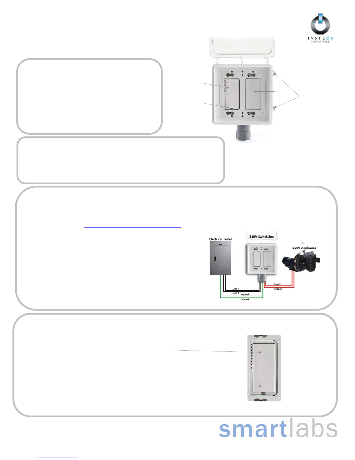
SwitchLincTM – INSTEON 220V On/Off Switch
Model: 2494S220
Remote Control of High Amperage 220 Volt Devices
SwitchLinc 220V provides Indoor and Outdoor control of up to 30 Amp
220 volt loads. Now you can automate your pool pumps, electric water
heaters and large sprinkler pumps – even air conditioning units using the
affordable and easy to install INSTEON (or even X10) technology. The
clear cover gives you visible status of your device even without opening
the cover.
9 Local Control
9 Handy Clear Cover for Visible Status
9 Weatherproof enclosure
9 220V INSTEON
9 Up to 30 Amps Inductive Load
Required Accessories
Depending on your particular application, you will likely need:
o 6 Large wire nuts
o ½” Conduit / wire sheathing
o Suitable junction box for connection to existing wiring
SwitchLinc
Set Button
“SwitchLinc 220V”
Blank
Plate
Mounting Tabs
(2 each side)
Installation
Important: Installation should be performed only by a qualified electrician or by a homeowner who is familiar and comfortable with electrical circuitry. If there are any
questions, consult an electrician. For setup questions contact Tech Support at SmartLabs for guidance. Tools required: electrical multi-meter, standard + Phillips screwdrivers
and a wire cutter/stripper. An appropriate conduit to house the SwitchLinc 220V’s wires and junction box to connect to your existing wiring are both required, but not supplied.
Two or more properly installed INSTEON Access Points (#2443) are recommended for every home. You will need to ID all your wires before beginning; for installation tips and
Introduction
tricks, see the Smarthome Wiki at http://wiki.smarthome.com/index.php?title=Main_Page
.
1) Disconnect power at the service panel
2) Using drywall screws (not supplied), or other suitable mounting hardware, mount the unit
to a wall, post or other suitable support
3) Route the 6 wires from SwitchLinc 220V through a suitable conduit connected to a
junction box
4) In the junction box connect:, using wire nuts (not included):
a. Green ground wire to ground
b. White Neutral wire to neutral
c. Both red wires to load as shown in diagram
d. Both black line wires to line as shown in diagram
5) Turn power back on at your service panel
6) Tap the bottom of the switch
SwitchLinc should turn on by default
SwitchLinc should turn off
Local Operation
Turning the Connected Load On and Off Locally
To turn the connected load/device on, tap the top of SwitchLinc
To turn the connected load/device off, tap the bottom of SwitchLinc
Page 1 of 2
Rev. 111908
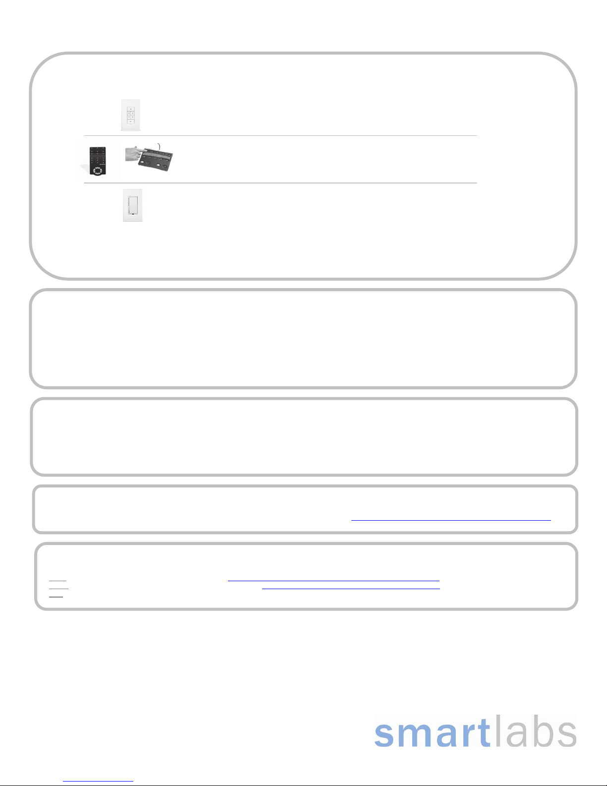
1) Identify your Controller type from the list below and perform the appropriate steps listed:
2) Tap the bottom of the SwitchLinc 220V (it will turn off if it was on)
3) Press & hold the SwitchLinc 220V’s Set button until the switch (and the connected load) turns on
4) Test by turning your SwitchLinc 220V On and Off from your controller
LEDs on your Controller will stop blinking (and it may beep)
Adding SwitchLinc 220V to a Controller’s Scene
Press & hold the desired button (for about 10 seconds) until its LEDs begin blinking
LEDs will continue blinking
Press & hold the ON button of the desired button pair (for about 10 seconds) until it beeps
LED will begin blinking
Press & hold the top paddle until LED begins blinking
LED will continue blinking
If your Controller is not shown – consult its Owner’s Manual
1) Press & hold the top (On) of the SwitchLinc 220V paddle for about 10 seconds (until the LED begins blinking)
2) Press & hold the Set button on your INSTEON responder
3) Test by tapping on and off on the SwitchLinc 220V, your responder should turn on and off in unison.
1
If your responder is a multi-button device (e.g. KeypadLinc), tap the button of choice before pressing & holding its Set button
SwitchLinc 220V contains a fully featured 2476S. Please see the owner’s manual for the 2476S at http://wiki.smarthome.com//index.php?title=2476SOwnersManual
for a full documentation of all its features.
Click: For Advanced Features and compatibility refer to: http://wiki.smarthome.com//index.php?title=2494S220OwnersManual
Click: For a wiki with tips, compatible codes and discussion refer to: http://wiki.smarthome.com//index.php?title=2494S220Wiki
Call: Friendly tech support @ 866-243-8018
SwitchLinc 220V’s top LED will be blinking
SwitchLinc 220V’s top LED will stop blinking
1) Press & hold the top (On) of the SwitchLinc paddle for about 10 seconds (until the LED begins blinking)
2) Using any X10 controller, send the desired X10 address 3 times (e.g. B5 ON -> B5 ON -> B5 ON)
3) Test by sending your X10 address followed by an on, then an off
SwitchLinc 220V’s top LED will be blinking
SwitchLinc 220V’s top LED will stop blinking
Controlling other INSTEON Devices from SwitchLinc 220V
1
for at least 3 seconds
Assign an X10 Address to SwitchLinc 220V
More Features
Questions ?
SmartLabs Limited Warranty – Sm artLabs warrants to original consumer of this
Page 2 of 2
Rev. 111908
product for a period of 2 years from date of purchase, this product will be f ree from
defects in material & workmanship & will per form in substantia l conformity with its
owner's manual. Warranty shall not ap ply to defects c aused by mis use or neglect.
©Copyright 2008 SmartLabs, 16542 Millikan Ave., Irvine, CA 92606, 866-243-8018
 Loading...