

Page 1
KeypadLinc On/Off
Owner’s Ma nual
INSTEON® 6-Button Scene Control Keypad, Dual-Band (#2487S)
Page 1 of 25 2487S - Rev: 1/21/2014 7:37 AM
Page 2

ABOUT KEYPADLINC On/Off ..................................................................................................................... 3
Features and Benefits ................................................................................................................................. 4
What’s in the box? ..................................................................................................................................... 4
Optional Accessories ................................................................................................................................. 5
Helpful Videos ........................................................................................................................................... 5
Installation ................................................................................................................................................... 5
Identifying the Electrical Wires in your Home ............................................................................................ 5
Tools Needed ............................................................................................................................................ 6
Button Naming ........................................................................................................................................... 6
Installation (for a circuit with only one switch) ........................................................................................... 6
Installation (for a circuit with more than 1 switch) ..................................................................................... 7
Using KeypadLinc in Virtual Multi-Way Circuits ........................................................................................ 8
Step-by-Step Instructions For Installing Multi-Way KeypadLinc Switches ................................................ 9
Special Instructions For Large Multi-Way Circuits................................................................................... 11
USING KEYPADLINC ................................................................................................................................ 13
Button Taps ............................................................................................................................................. 13
Press and Holds ...................................................................................................................................... 13
INSTEON Scenes ....................................................................................................................................... 13
Add KeypadLinc Button to a Scene as a Controller (also known as Linking Mode) ............................... 14
Add KeypadLinc Button to a Scene as a Responder (also known as Responder Setup) ...................... 15
Remove KeypadLinc Button from a Scene as a Responder (also known as Responder Setup) ........... 15
Removing KeypadLinc from a Scene as a Controller (also known as Unlinking Mode) ......................... 15
Air Gap..................................................................................................................................................... 16
Changing a KeypadLinc Button ............................................................................................................... 16
ADVANCED FEATURES ........................................................................................................................... 17
Using KeypadLinc as a Phase Bridge (Phase Bridging Detection Mode) ............................................... 17
Add Multiple Scene Responders at Once (also known as Multi-Linking Mode) ...................................... 17
Remove Multiple Scene Responders at Once (also known as Multi-Unlinking Mode) ........................... 18
Control Groups (also known as Cross-Linking) ....................................................................................... 18
Changing Button Behavior (Toggle / Non-Toggle Mode) ........................................................................ 19
“Radio” Button Groups (only 1 LED of “n” at a time) ............................................................................... 20
Adjust LED Brightness ............................................................................................................................. 20
Turn Button Beep On or Off..................................................................................................................... 20
Power Restore ......................................................................................................................................... 21
Add X10 Address to a Button .................................................................................................................. 21
Remove X10 Address from a Button ....................................................................................................... 21
Advanced X10 Programming................................................................................................................... 21
Factory Reset .......................................................................................................................................... 22
ADDITIONAL RESOURCES ............................................................................ Error! Bookmark not defined.
TROUBLESHOOTING ................................................................................................................................ 22
Certification and Warranty ....................................................................................................................... 24
Certification .............................................................................................................................................. 24
FCC and Industry Canada Compliance Statement ................................................................................. 24
Limited Warranty ..................................................................................................................................... 24
Limitations ............................................................................................................................................ 24
Page 2 of 25 2487S - Rev: 1/21/2014 7:37 AM
Page 3
ABOUT KEYPADLINC On/Off
KeypadLinc On/Off (Dual-Band) is an elegant relay switch plus scene controller in one. In the 6-button
configuration, the ON and OFF buttons control the connected load (light/appliance). Both the ON/OFF
buttons plus the other 4 buttons can all control their own scene members (other INSTEON devices which
respond to button presses on KeypadLinc). Furthermore, each button on KeypadLinc can itself be a
member of countless scenes (giving you remote control of both the connected load as well as the scene
buttons’ LEDs) from other INSTEON devices. KeypadLinc On/Off Dual-Band supports voltages from 120
to 277V, making it the perfect energy saving, wireless controller for commercial building automation
systems.
Page 3 of 25 2487S - Rev: 1/21/2014 7:37 AM
Page 4

Features and Benefits
• Easy to setup and use
• Integrated 20 amp relay (incandescent loads up to 1800 watts)
• Each button can be a scene controller
• Each button can also be a scene responder
• Each button can control the other buttons on the keypad (as well as remote devices)
• Can support up to 400 scenes
• Multiple buttons can be included in the same scene
• Each button can be configured to:
o Toggle between sending Ons and Offs (default)
o Always send an On (scene trigger mode)
o Always send an Off
• Dimmable LEDs
• Beeper
o Makes setup a breeze
o Can function as a chime module
o Configurable to beep on each button press if desired
• X10 Compatible
• Wires in like standard wall switch (requires a NEUTRAL)
• Supports 3-way, 4-way and up multi-way circuits without traveler wires
• Color change kits available
• LED color change kits available
• 8 button change kit available
• Dual-band for the ultimate in reliability
• Acts as an access point for battery powered devices
• Acts as a phase bridge
• All settings preserved through power failures
• Using software you can lockout local programming to prevent accidental changes
• Two-year warranty
What’s in the box?
• KeypadLinc On/Off – INSTEON 6-Button Scene Control Keypad, Dual-Band
• 4 wire nuts
• 2 mounting screws
• Quick Start Guide
Page 4 of 25 2487S - Rev: 1/21/2014 7:37 AM
Page 5
Accessories
Link
• LINE - usually black, may also be called HOT or LIVE, carries electricity into the outlet
Optional Accessories
Custom Etched and PrePrinted Buttons
Color and 6/8 Button
Change Kits (15)
Blank Buttons
Clear Buttons
LED Color Change Kit
http://www.smarthome.com/_/KeypadLinc/KeypadLinc_Custom_Buttons
/_/2vj/2wf/nav.aspx
http://www.smarthome.com/_/KeypadLinc/KeypadLinc_Change_Kits/_/2
vj/2wb/nav.aspx
http://www.smarthome.com/2401BT10/Blank-10-Button-Set-forKeypadLinc-White/p.aspx
http://www.smarthome.com/2401CLB/6-or-8-Button-Change-Kit-forKeypadLinc-Clear/p.aspx
http://www.smarthome.com/2401L/LED-Color-Change-Kit-forKeypadLinc-4-Color/p.aspx
Helpful Videos
- Linking to a KeypadLinc
- Unlinking from a KeypadLinc
- Changing out the KeypadLinc Buttons
- Adding LED Diffusers to the KeypadLinc
Installation
CAUTIONS AND WARNINGS
Read and understand these instructions before installing and retain them for future reference.
KeypadLinc is intended for installation in accordance with the National Electric Code and local regulations in the United States or the
Canadian Electrical Code and local regulations in Canada. Use indoors only. KeypadLinc is not designed nor approved for use on
power lines other than 120VAC or 277VAC 60Hz, single phase. Attempting to use KeypadLinc on non-approved po wer lines m ay
• Use only indoors or in an outdoor rated box
• Be sure that you have turned off the c ircuit breaker or removed the fuse for the circ uit you are installing KeypadLinc in.
Installing KeypadLinc with the power on will expose you to dangerous voltages.
• Connect only copper or copper-clad wire to KeypadLinc
• KeypadLinc may feel warm during operation. The amount of heat generated is within approved limits and poses no
hazards. To minimize heat buildup, ensure that the area surrounding the rear of KeypadLinc is as clear of clutter as
possible.
• Each KeypadLinc is assigned a unique INSTEON ID, which is printed on the device’s label.
• To reduce the risk of overheat ing and possible damage to ot her equipment, use KeypadLinc to c ontrol no more than 20
Amps (1800 Watts of incandescent) at 110VAC or 277VAC.
• You will need a flathead screwdriver, a Philips head screwdriver and a voltage meter to install KeypadLinc
To install KeypadLinc, you will need to identify the following four wires:
Page 5 of 25 2487S - Rev: 1/21/2014 7:37 AM
have hazardous consequences.
Identifying the Electrical Wires in your Home
Page 6

• LOAD (Optional) - usually black or red, feeds power to a connected lighting/applianc e fixture.
KeypadLinc for you. If you have any questions, please consult an electrici an or call: 8 66-243-8022
• NEUTRAL - usually white
• GROUND - bare copper wire or metal fixture (if grounded)
If you are having difficulties identifying wires, consult an electrician to help you.
IMPORTANT!
If you are not knowledgeable about, and comfortable with, electrical circuitry, you should have a qualified electrician install
Tools Needed
- A slotted screwdriver for trim plate
- A Phillips screwdriver for KeypadLinc
- A wire cutter and stripper if the switch you are replacing requires you to cut the wires to remove them
- Voltage Tester - To identify the wires inside the junction box
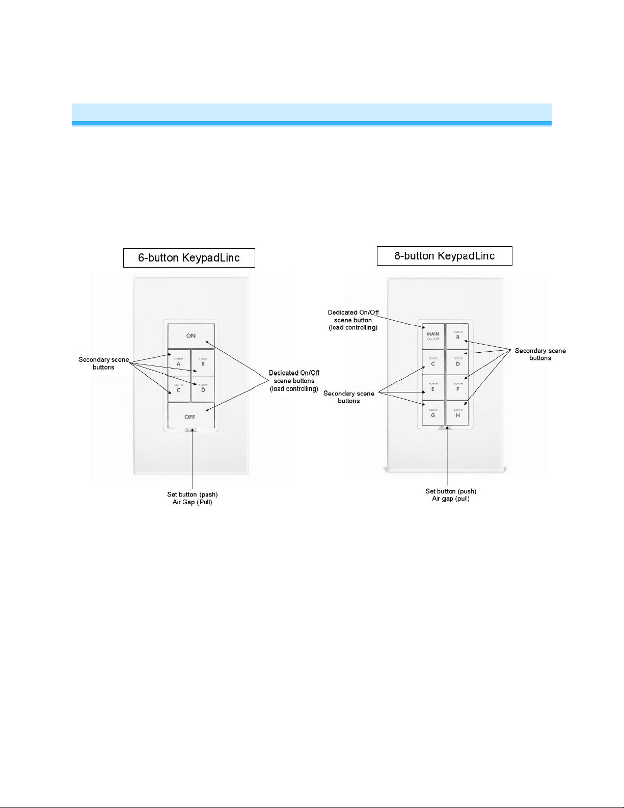
Button Naming
Throughout this manual, we will use the following naming conventions:
Installation (for a circuit with only one switch)
1) At the circuit breaker or fuse panel, disconnect the power for all of the circuits in the switch junction
box. Verify that the power is off by trying to turn on the lights controlled by the switches.
2) Remove the trimplate from the switch junction box, and then unscrew the switch you are replacing
and pull it out from the junction box
3) Disconnect the wires from the switch you are replacing. If the wires cannot be detached by
unscrewing them, cut the wires where they enter the switch, then strip ½” of insulation off the ends
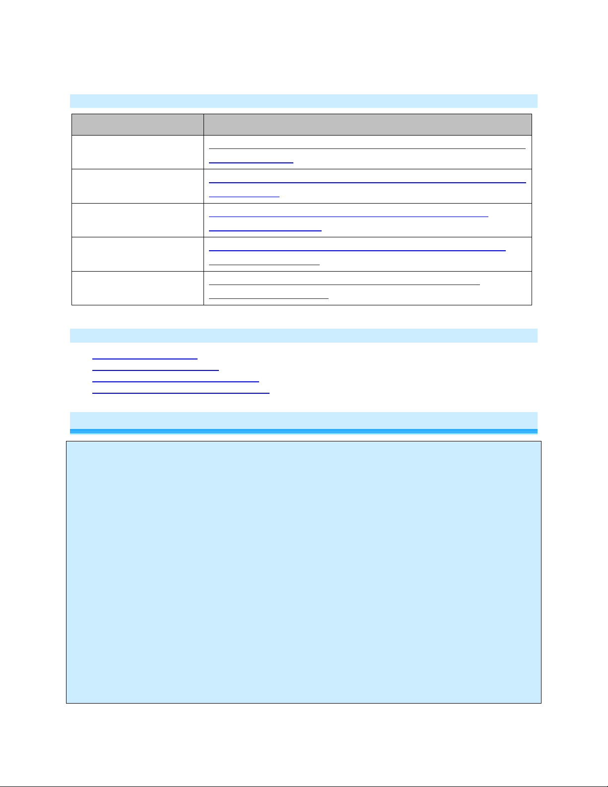
4) If you are installing KeypadLinc into a standard 2-way circuit (where only one switch controls the
load), follow the diagram below to identify and connect the LINE, LOAD, NEUTRAL
wires. If the colors of the wires do not match the diagram, be sure you have identified the wires
correctly before connecting them.
5) If you are installing KeypadLinc into a multi-way circuit (where more than one switch controls the
load), follow the instructions in the section Installing KeypadLinc in a Multi-Way Circuit
and connect the LINE, TRAVELER, NEUTRAL, and GROUND wires
1
If there is no NEUTRAL wire in the junction box, please consult an electrician or call: 866-243-8022
Page 6 of 25 2487S - Rev: 1/21/2014 7:37 AM
1
, and GROUND
, to identify
Page 7
6) After you have connected all of the wires, ensure that all of the wire connectors are firmly attached
and that there is no exposed copper except for the GROUND wire
7) Orienting KeypadLinc with the Set button on the bottom, gently place it into the junction box, and
then screw it into place
8) Enable power to the switch from the circuit breaker or fuse panel
9) Verify KeypadLinc is working properly by turning the light on and off
10) Reinstall the trim plate
Installation (for a circuit with more than 1 switch)
If more than one switch controls a single set of lights (called a "load"), the switches are part of a multi-way
circuit. A 3-way circuit (the most common) uses two switches to control the load, a 4-way circuit uses
three switches, and so on.
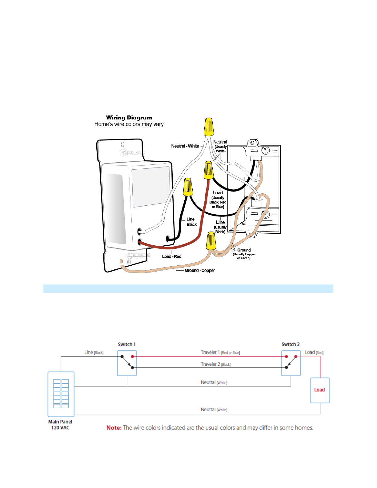
Here is how a typical wired-in, 3-way circuit (with two switches) works:
Page 7 of 25 2487S - Rev: 1/21/2014 7:37 AM
Page 8
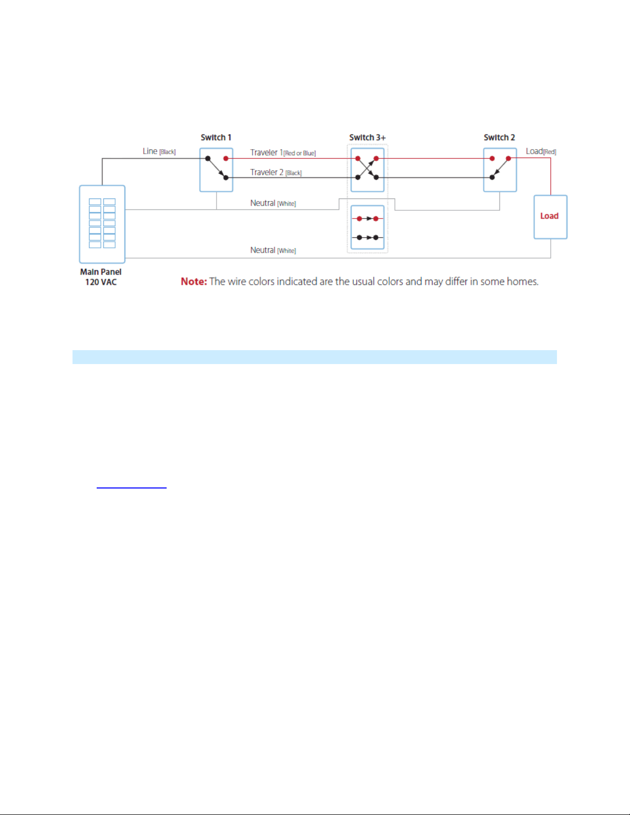
A wired-in 4 or more-way circuit (with three or more switches) has additional switches added in the middle
of the circuit. In the diagram below, the additional switch (Switch 3+) is shown in two different positions
since wiring can vary from home to home.
To learn more about multi-way circuits, try Googling the search terms "3-way switch" or "4-way switch."
Using KeypadLinc in Virtual Multi-Way Circuits
By creating virtual, multi-way circuits, you can use KeypadLincs to replace switches in 3-way, 4-way and
higher multi-way circuits that are already wired into your home. Or, you can use them to create multi-way
circuits where there is no existing, multi-way wiring thus saving the hassle and expense of re-wiring.
In a virtual multi-way circuit, only one KeypadLinc, called the Key p ad Linc Pr im ary , actually connects to
the load in the multi-way circuit. Additional Ke ypadLincs, called KeypadLinc Secondaries, are not
connected to the load, but only to power (LINE and NEUTRAL wires). All of the Ke ypadL incs
communicate with the others us ing INST EO N. Af ter wiring in the KeypadLincs, you can create the virtual
multi-way circuit by setting up all of the KeypadLincs (or KeypadLinc and switches) to control each other
(see Control Groups
circuit using a KeypadLinc plus other INSTEON switch or keypad.
). The diagram below shows a previously wired 3-way circuit, now a virtual 3-way
Page 8 of 25 2487S - Rev: 1/21/2014 7:37 AM
Page 9

1) Find the LINE wire. Your first task is to find out which switch junction box is
- Disconnect the wires from the old switches. If the wires cannot be detached by unscrewing them, cut
- Using a volt meter or voltage tester, individually test each wire for voltage. When you measure
Notes:
- One of the TRAVELER wires (TRAVELER 1, Red) is not used, so you will cap it off at both ends
- The other TRAVELER (TRAVELER 2, Black) you will convert to a LINE wire. In the Secondary
KeypadLinc’s junction box, connect TRAVELER 2 to the existing LINE and also to the KeypadLinc
Secondary’s LINE wire. In the other junction box at the other end, you will connect TRAVELER 2 to
the KeypadLinc Primary’s LINE wire.
- The KeypadLinc Primary’s LOAD wire gets connected to the actual lights that are being controlled
- The LOAD wire for any KeypadLinc Secondaries that you will be installing will not be connected to
anything, so cap those LOAD wires off with a wire nut
- All KeypadLincs, whether they are Primaries or Secondaries, must be connected to NEUTRAL and to
GROUND. You may notice that the switches you are replacing will not normally have a connection to
NEUTRAL. KeypadLinc will not function without a NEUTRAL. Please consult an electrician or call us
at 866-243-8022.
Step-by-Step Instructions For Installing Multi-Way KeypadLinc Switches
When replacing a 3-way mechanical switch, each switch will have three wires connected to it from the
wall box. Four-way or greater circuits will have four wires connected to the switches in the center of the
circuit. For this tutorial, we will follow the most commonly used wire colors for homes in North America.
the one where the electricity comes into the circuit. This box will contain the
LINE wire.
- Disable power at the circuit breaker or fuse panel
- Pull all the switches in the multi-way circuit out of their junction boxes.
Each switch should have three wires connected to it. If the circuit is 4way or greater, some of the switches will have four wires.
the wires where they enter the switch and then strip ½ inch of insulation off the ends.
- Make sure that none of the wi res are touching anything and turn the electricity back on
Page 9 of 25 2487S - Rev: 1/21/2014 7:37 AM
Page 10

between 110 and 120 Volts AC, that wire is the LINE wire (usually black).
- The other two wires (usually black and red) are the TRAVELERS and go to the next junction box.
TRAVELER wires are usually in the same cable sheath.
- Turn off the electricity to resume installation
2) Connect the KeypadLinc Secondary’s LINE wire. The KeypadLinc that
will be the Secondary goes in the junction box where you found the LINE
wire. Connect the LINE wire that you found, the black TRAVELER, and the
KeypadLinc Secondary’s black LINE wire all together with a single wire nut.
3) Cap the other TRAVELER wire. The other TRAVELER wire (usually red)
will not be used, so put a wire nut on the end of it.
4) Cap the red LOAD wire from the KeypadLinc Secondary. Put a wire nut
on the end of the KeypadLinc Secondary’s LOAD wire to ensure that it won’t
connect to anything.
5) Connect the KeypadLinc Secondary’s NEUTRAL wire. Locate the group
of NEUTRAL wires (usually white) in the rear of the box. The old switch
should not have been connected to the NEUTRAL wires, but KeypadLinc
requires this connection in order to draw a small amount of power for itself.
Connect the KeypadLinc Secondary’s white NEUTRAL wire to the other
NEUTRAL wires with a wire nut.
6) Connect the KeypadLinc Secondary’s GROUND Wire. Connect the bare
copper GROUND wire to the other GROUND wire in the junction box.
Page 10 of 25 2487S - Rev: 1/21/2014 7:37 AM
Page 11

7) Install additional switch/keypad Secondaries. If you have a 4-way or greater switching circuit, see
12) Connect the KeypadLinc Primary’s NEUTRAL and GROUND wires. Repeat steps 5 and 6 with the
Special Instructions For Large Multi-Way Circuits at the end of this section.
8) Identify the wires for the KeypadLinc Primary. The KeypadLinc Primary is the KeypadLinc that will
actually control the load. In the junction box where you will install the KeypadLinc Primary, find the wire that
carries power from the switch to the lights. This wire, called the LOAD wire, is commonly red.
In the same junction box, there will also be the two TRAVELER wires from the first box, often both in the
same cable sheath. Identify the TRAVELER wire (black) that you connected the LINE wire to in the first
junction box.
If you’re not sure which is the TRAVELER wire connected to the LINE wire, you can use the same method
described in step 1 to find it. Turn on the power (taking the same precautions) and use a voltmeter to find
the wire with 120 Volts AC on it.
Make sure the power is turned off again before proceeding.
9) Connect the KeypadLinc Primary’s LINE wire. Use a wire nut to
connect the TRAVELER wire (usually black) that you identified as
connected to the LINE wire to the KeypadLinc Primary’s black LINE wire.
10) Cap the other TRAVELER wire. The other TRAVELER wire (usually
red) will not be used, so put a wire nut on the end of it.
11) Connect the KeypadLinc Primary’s LOAD wire. Use a wire nut to
connect the LOAD wire (usually red) to the KeypadLinc Primary’s red
LOAD wire.
KeypadLinc Secondary.
13) Finish installation. Return to Installing KeypadLinc and continue on from step 5.
14) Refer to Control Groups for instructions on scene setup
Special Instructions For Large Multi-Way Circuits
If your lighting circuit includes more than two switches controlling a single set of lights, those extra
switches will have four wires connected to them. Two of the wires are TRAVELERS from the preceding
switch and the other two are TRAVELERS to the next switch in the chain. You will be converting the black
TRAVELER wires to the LINE wires and replacing the old 4-wire switches with KeypadLinc Secondaries.
Page 11 of 25 2487S - Rev: 1/21/2014 7:37 AM
Page 12

1) Connect the KeypadLinc Secondary’s LINE Wire. Use a wire nut to connect both black
TRAVELER wires to the KeypadLinc Primary’s black LINE wire.
2) Cap the two unused TR AVELERS. The other two TRAVELER wires (usuall y red) will not be used,
so put wire nuts on the ends of them.
3) Cap the red LOAD wire from the KeypadLinc Secondary. Put a wire nut on the end of the
KeypadLinc Secondary’s LOAD wire to ensure that it won’t connect to anything.
4) Connect the KeypadLinc Secondary’s NEUT RAL and GROUND wires. Repeat steps 5 and 6 of
Step-by Step Instructions for Installing Multi-Way KeypadLincs.
Page 12 of 25 2487S - Rev: 1/21/2014 7:37 AM
Page 13

USING KEYPADLINC
Button Type
Button’s LED
Tap
Double-tap
Toggle
Off
Turn Scene On
Turn Scene Members On Instantly
Toggle
On
Turn Scene Off
Turn Scene Members Off Instantly
Always On
Either
Turn Scene On
Turn Scene Members On Instantly
Always Off
Either
Turn Scene Off
Turn Scene Members Off Instantly
First Press and
Hold
(e.g. if last was brightening, it will dim)
(e.g. if last was brightening, it will dim)
Always On
Either
Brighten Scene until release
Always Off
Either
Dim Scene until release
Button Taps
Press and Holds
Button Type Button’s LED
Toggle Off
Toggle On
Notes:
1) The Load will react just like the scene responders to button presses of MAIN when in 8-Button
configuration
2) The LED will mimic the on/off status of a dimmer whose scene level is 100% bright
Brighten Scene until
release
Dim Scene until
release
Subsequent Press and Holds
Opposite of last Press and Hold
Opposite of last Press and Hold
INSTEON Scenes
Scene: One or more INSTEON devices which respond simultaneously to scene commands (e.g. button
presses). When the scene is activated (turned “on”), all devices return to the states they were at when the
scene was programmed. INSTEON scenes let you activate dramatic lighting moods at the touch of a
button. For example, you can set all the lights in a scene to dim to 50% or turn certain lights on while
turning others off. INSTEON scenes are easy to set up, just follow the directions below.
The below diagram provides an overview of the options available in the KeypadLinc Setup Mode and how
to navigate between the options. The Advanced Setup Features are highlighted in yellow.
Page 13 of 25 2487S - Rev: 1/21/2014 7:37 AM
Page 14

• Tap the scene button you wish to setup before entering setup mode
• Advanced setup features are highlighted in yellow
• Toggle: Cycles autom atical ly betwee n “T oggle”, “A lwa ys Off” , “Alwa ys On” upon entr y into this mode,
then exists to Normal Operating Mode
Add KeypadLinc Button to a Scene as a Controller (also known as Linking Mode)
1) Tap the KeypadLinc Scene button of choice (doesn’t matter if you send an on or an off)
2) Press and hold KeypadLinc ’s Set button unt il it bee ps
KeypadLinc’s scene button’s LED will blink
All illuminated LEDs on KeypadLinc will brighten to 100%
You will have 4 minutes to c omplete the next step before Linking Mode automatically times out.
3) Adjust the scene responder to the “state” you wish it to be at when the Scene is activated from
KeypadLinc (e.g. 50%, 25% or even OFF)
2
(Note: manual tap of responder button/paddle/etc. is
required)
4) Press and hold the Responder’s Set button until it beeps (or until its LED/load flashes)
KeypadLinc will double-beep and its scene button’s LED will stop blinking
KeypadLinc’s LEDs will return to normal brightness
Responder’s LED will stop blinking (it may also double-beep)
5) Confirm that Scene addition was successful by tapping on/off on your chosen KeypadLinc button
The Responder will toggle between the Scene level and Off
6) If you wish to add more responders to KeypadLinc, repeat steps 1-5 for each additional scene
responder (or see Add Multiple Scene Responders at O nce
)
2
If the Responder is a multi-scene device, tap the Scene button you wish to control until its LED is in the desired state (on or off)
Page 14 of 25 2487S - Rev: 1/21/2014 7:37 AM
Page 15

Add KeypadLinc Button to a Scene as a Responder (also known as Responder Setup)
1) Press and hold the Scene Controller (the other INSTEON device) button until it beeps3
Controller’s LED will blink
2) When the scene is activated
• If you want the LED
4
ON
i. Tap KeypadLinc’s Scene Responder button until LED is on
• If you want the LED OFF
i. Tap KeypadLinc’s Scene Responder button until LED is off
3) Press and hold KeypadLinc ’s Set button unt il it dou bl e-beeps
KeypadLinc’s scene butt on’s LED will flash once and return to its previous state
Controller will (Beep)-(Beep)
5
and its LED will stop blinking
4) Confirm that Scene addition was successful by tapping on then off on the controller’s scene button
KeypadLinc’s scene butt on’s LED will toggle between On and Off
Remove KeypadLinc Button from a Scene as a Responder (also known as Responder
Setup)
Note: If you are going to discontinue using KeypadLinc, it is very important that you remove it from all of
its scene controllers. Otherwise, the controllers will retry commands repetitively and creating network
delays.
1) Press and hold the Controller’s Scene button
6
2) Press and hold the Controller’s Set button until it beeps
(or LED blinks)
Controller’s LED blinking
3) Press and hold the Controller’s Set button until Controller beeps again
6
(5 seconds if no beeper)
Controller’s LED blinking
4) Tap KeypadLinc’s Responder Button you are removing
5) Press and hold Set button on KeypadLinc until it doubl e-beeps
KeypadLinc’s scene butt on’s LED will flash once and return to previous state
Controller will (Beep)-(Beep)
7
and its LED will stop blinking
6) Confirm that Unlinking was successful by tapping the Controller’s scene button a couple times
KeypadLinc will no longer respond
Removing KeypadLinc from a Scene as a Controller (also known as Unlinking Mode)
Note: If you are no longer going to use a scene responder of KeypadLinc , it is very im portant t hat you
remove its scene membership. Otherwise, KeypadLinc will retry every scene command repetitively, thus
creating network delays.
1) Tap the scene button on KeypadLinc
3
If the controller does not have a beeper, wait until its LED begins blinking
4
Load will mimic LED state for toggle buttons, for the ON and OFF buttons tap the desired scene state
5
Most models
6
For devices without beepers hold until its LED begins blinking (this may take 10+ seconds)
7
Most models
Page 15 of 25 2487S - Rev: 1/21/2014 7:37 AM
Page 16

2) Press and hold KeypadLinc’s Set button until it beeps
KeypadLinc’s LED will begin blinking
All illuminated LEDs on KeypadLinc will brighten to 100%
3) Press and hold the KeypadLinc’s Set button until it beeps again
KeypadLinc’s LED will continue blinking
4) If responder has multiple buttons, tap the button you wish to remove from scene
5) Press and hold the Responder’s Set button until it double-beeps (or LEDS blink)
KeypadLinc will (Beep)-(Beep) and its scene LED will stop blinking
KeypadLinc’s LEDs will return to normal brightness
Responder will (Beep)-(Beep) and its LED will flash once
6) Confirm that Unlinking was successful by tapping the scene button on KeypadLinc a couple times
The Responder will not respond
Air Gap
The "air gap" removes power from the connected load (controlled circuit) when pulled out. This is handy
for replacing bulbs without turning off the circuit breaker.
Disable Power:
- To disable power, pull the Set button at the bottom of the switch out as far as it will go, about 1/8 inch.
(It might be helpful to use a small screwdriver.) This will open the mechanical contacts and will
remove all power to the INSTEON device and the load that it controls until the Set button is pushed
back in. However, because the INSTEON device's settings are stored in non-volatile memory, setup
information will not be lost when the unit is unpo were d . IMPORTANT: Make sure circuit is off by
observing light going off (if possible) and LEDs on KeypadLinc turning off before performing work on
the switched circuit.
Restore Power:
- To restore power, tap the air gap back into place, until its top is even with the trim frame. Important:
Do not hold the Set Button in for more than a second. If held in longer, you may inadvertently
perform a factory reset.
Changing a KeypadLinc Button
KeypadLinc buttons may be changed to customize appearance. Please use
care – the button frame can be damaged and/or broken during this process.
Using a small, slotted screwdriver (ONLY) pry up on the sides of the keys
from the middle of the keypad (as shown). Make sure you are centered on
the key as there is a small “lip” to pull up on located there. The large buttons
have a small "lip" on the left and right side.
Should any damage occur to KeypadLinc during customization, please contact the INSTEON Support Line at
866-243-8022 and we will be happy to replace your frame.
Page 16 of 25 2487S - Rev: 1/21/2014 7:37 AM
Page 17

ADVANCED FEATURES
Using KeypadLinc as a Phase Bridge (Phase Bridging Detection Mode)
KeypadLinc automatically bridges the electrical phases in your home (via communications with dual-band
devices on the “other phase”). The following procedure to confirm that phases are bridged via
KeypadLinc:
1) Start Phase Bridging Detection Mode by tapping the Set button on KeypadLinc four times quickly
KeypadLinc will begin (Beeping)
KeypadLinc LEDs that are on will illuminate at full brightness
Other dual-band devices L EDs will illu mi nat e at 100% brigh tness
2) Check the LED behavior of the “other” dual-band devic es
- If the “other” dual-band device is blinking green
i. it is within range and not on the same phase, proceed to next Step
- If they are not blinking green
i. Try moving the “other” device, check other dual-band devices or begin
3) Tap KeypadLinc’s Set Button
KeypadLinc will stop beeping and LEDs return to previous state
9
test from a different initiator
8
Other devices’ LEDs will stop blinking
Add Multiple Scene Responders at Once (also known as Multi-Linking Mode)
1) Set each of the Responders to the desired scene activation state10
2) Tap the Scene controller button on KeypadLinc
3) Press and hold KeypadLinc’s Set Button until it beeps
KeypadLinc’s scene button’s LED will begin blinking
All illuminated LEDs on KeypadLinc will brighten to 100%
4) Tap KeypadLinc’s Set Button
KeypadLinc’s scene button’s LED will continue blinking
5) For each responder you are adding:
- Tap the responder button (if it is a multi-button device)
- Press and hold set button until it beeps (or, about 3 seconds until LED flashes)One at a
time, press and hold each of the Responder’s Set buttons for 3 seconds
6) Tap KeypadLinc’s Set Button
KeypadLinc’s scene button’s LED will stop blinking
KeypadLinc’s LEDs will return to normal brightness
7) Test scene by tapping the scene button a couple of times
8
Or is simply blinking for single colored LEDs. If the “other” dual-band device is a KeypadLinc Dual-Band, the 4 middle LEDs will blink.
9
Or are not blinking at all for single colored LEDs. If the “other” dual-band device is a KeypadLinc, any LEDs that are on will go to full bright.
10
For KeypadLinc buttons, tap the button until its LED is in the desired scene activation state
Page 17 of 25 2487S - Rev: 1/21/2014 7:37 AM
Page 18

All the responders added above should respond to scene activations
Remove Multiple Scene Responders at Once (also known as Multi-Unlinking Mode)
1) Tap the Scene controller button on KeypadLinc
2) Press and hold KeypadLinc’s Set Button until it beeps
KeypadLinc’s scene button’s LED will begin blinking
All illuminated LEDs on KeypadLinc will brighten to 100%
3) Press and hold KeypadLinc’s Set Button again until it beeps again
KeypadLinc’s scene button’s LED will continue blinking
4) Tap KeypadLinc’s Set Button
KeypadLinc’s scene button’s LED will continue blinking
5) For each responder you are removing
- Tap the responder button (if it is a multi-button device)
- Press and hold set button until it beeps (or, about 3 seconds until LED flashes). One at a
time, press and hold each of the Responder’s Set buttons for 3 seconds.
6) Tap KeypadLinc’s Set Button
KeypadLinc’s scene button’s LED will stop blinking
KeypadLinc’s LEDs will return to normal brightness
7) Test scene by tapping the scene button a couple of times
All the responders added above should respond to scene activations
Control Groups (also known as Cross-Linking)
Control groups will all respond the same to all scene activations and de-activations (off’s). A common
example is a 3-way lighting circuit. 4-way lighting circuits as well as scenes with multiple controllers and
only 1 “load bearing” responder are also examples of control groups.
3-Way Circuit Example (a Control Group with 2 members)
1) Turn both switches/dimmers on – to the same, desired scene level
2) Press and hold Switch A’s set button until it beeps (or LED blinks)
Switch A’s LED will begin blinking
3) Press and hold Switch B’s set button unt il it double-beeps (or LED flashes)
Switch B will (Beep)-(Beep) and its LED will flash once
Switch A will (Beep)-(Beep) and its LED will stop blinking
4) Press and hold Switch B’s set button unt il it beeps (or LED bl ink s )
Switch B’s LED will begin blinking
5) Press and hold Switch A’s set button unt il it double-beeps (or LED flashes)
Switch A will (Beep)-(Beep) and its LED will flash once
Switch B will (Beep)-(Beep) and its LED will stop blinking
Page 18 of 25 2487S - Rev: 1/21/2014 7:37 AM
Page 19

6) Test the group by controlling the load from Switch A and then Switch B
The Load, Switch A and Switch B will all remain in synch
Control Groups with more than 2 members
Software is recommended for larger control groups. However, the following steps, when carefully
followed, will also work.
1) Turn all N switches/dimmers on – to the same, desired scene level
2) Press and hold Switch A’s set button unt il it beeps (or LED bl ink s )
Switch A’s LED will begin blinking
3) Tap Switch A’s set button
4) Press and hold Switch B’s set button unt il it double-beeps (or LED flashes)
Switch B will (Beep)-(Beep) and its LED will flash once
5) Repeat prior step for Switch C, Switch D……….Switch N
Each Switch will (Beep)-(Beep) and its LED wi ll flash once
6) Tap Switch A’s set button
7) Repeat Steps 2-5 for Switches B through N
8) Test the group by controlling the load from each switch
The Load(s) and all the switches will all remain in synch
Changing Button Behavior (Toggle / Non-Toggle Mode)
You can change any button, except the dedicated On/Off buttons, to any one of three Button Modes:
• Toggle (default) – toggles between ON and OFF commands each time it is pressed
• Always Off – sends ON every time it is pressed
• Always On – sends OFF every time it is pressed
To change the Button Mode
1) Tap the desired button
2) Press and hold KeypadLinc’s Set button until it beeps
The button’s LED
All illuminated LEDs on KeypadLinc will brighten to 100%
3) Press and hold KeypadLinc’s Set button a 2nd time until it beeps a 2nd time
The button’s LED
4) Press and hold KeypadLinc’s Set button a 3
The button’s LED
The button rotates to the next Button Mode in the cycle:
Toggle
Always Off
Always On
5) If you wish to rotate KeypadLinc to the next Button Mode in the cycle, repeat steps 2-4
will begin blinking
will continue blinking
rd
time until it beeps a 3rd time
will stop blinking
→
Always Off
→
Always On
→
Toggle
Page 19 of 25 2487S - Rev: 1/21/2014 7:37 AM
Page 20

“Radio” Button Groups (only 1 LED of “n” at a time)
This feature is especially handy if you have multiple scenes controlling the same devices, such as Lights Bright,
Lights Medium and Lights Off. When you press any of the scene buttons, the “others” LEDs will turn off (as if
they were scene responders).
Because of their complexity, software is recommended for radio button
group setup.
1) Tap each radio group button until its LED is On
2) Press and hold button A until it beeps (about 10 seconds)
3) Press and hold button B until it beeps (about 10 seconds)
4) If you are grouping more than 2 buttons
a. Repeat steps 1-3 inserting buttons C, D, etc. into Step 3
5) Repeat steps 1-4, inserting button B into step 2 and all other buttons into step 3 (and 4)
6) Tap each radio group button until its LED is Off
7) Press and hold button A until it beeps (about 10 seconds)
8) Press and hold button B until it beeps (about 10 seconds)
9) If you are grouping more than 2 buttons
a. Repeat steps 6-8 inserting buttons C, D, etc. into Step 8
10) Repeat steps 6-9, inserting button B into step 7 and all other buttons into step 8 (and 9)
Adjust LED Brightness
KeypadLinc’s LEDs can be set to any one of 32 brightness levels.
If KeypadLinc in 6-Button Configuration
1) Simultaneously tap the A and D buttons
KeypadLinc
2) Use the On and Off buttons to adjust the LED brightness
3) When you have reached the desired brightness, simultaneously tap the A and D buttons again
KeypadLinc
If KeypadLinc in 8-Button Configuration
1) Simultaneously tap the C and F buttons
KeypadLinc
2) Press and hold the On button to adjust the LED brightness. (The button will toggle between brightening
and dimming.)
3) When you have reached the desired brightness, simultaneously tap the C and F buttons
KeypadLinc
will beep
will beep
will beep
will beep
Turn Button Beep On or Off
The KeypadLinc buttons can be set to Beep Mode so KeypadLinc will beep every time a button is used. By
default, Beep Mode is off.
If KeypadLinc in 6-Button Configuration
Simultaneously tap the B and C buttons
KeypadLinc
Keypad’s Beeper will toggle to on (if was off) or off (if it was on)
will beep
Page 20 of 25 2487S - Rev: 1/21/2014 7:37 AM
Page 21

If KeypadLinc in 8-Button Configuration
Simultaneously tap the D and E buttons
KeypadLinc
Keypad’s Beeper will toggle to on (if was off) or off (if it was on)
will beep
Power Restore
KeypadLinc stores all of its scenes, properties, etc. in non-volatile memory. As such, all settings are retained
after a power outage. Upon power being restored, KeypadLinc will return its connected load and all LEDs to
their states prior to power outage.
Add X10 Address to a Button
1) Tap the KeypadLinc button
2) Press and hold KeypadLinc ’s Set button unt il it bee ps
The button’s LED will begin blinking
3) Send the desired X10 Address, plus ON, 3 times (e.g. send B5, BON, B5, BON, B5, BON)
KeypadLinc will double-beep and the button’s LED will stop blinking
Remove X10 Address from a Button
If you are no longer going to control KeypadLinc with an X10 address, it is very important that you remove
its X10 address. Otherwise, KeypadLinc w il l still listen for X10 commands (somewhat hindering INSTEON
reception) and may respond to spurious X10 “noise” which is unavoidable.
1) Tap the KeypadLinc button of choice
2) Press and hold KeypadLinc ’s Set button unt il it bee ps
The button’s LED will begin blinking
3) Press and hold KeypadLinc’s Set button again until it beeps again
The button’s LED will continue blinking
4) Send the X10 Address, plus ON, 3 times (e.g. send B5, BON, B5, BON, B5, BON)
KeypadLinc will double-beep and the button’s LED will stop blinking
Advanced X10 Programming
Instructions on setting X10 primary address and scene addresses can be found online:
http://www.insteon.com/insteon-x10-programming.html
Page 21 of 25 2487S - Rev: 1/21/2014 7:37 AM
Page 22

Problem
Possible Cause
Solution
indicator lights under
Make sure the circuit breaker is turned on.
Make sure the air gap (Set button) is not pulled out.
Check the junction box wires to ensure all connections
are tight and no bare wires are exposed.
Make sure the Line and Load wire are not mis-wired
inside the junction box.
Check the connected load to ensure all connections are
tight and no bare wires are exposed.
The Controller or Responder
from it.
The Controller or Responder
opposite power line phases.
Add additional INSTEON devices or move around
signals.
Factory Reset
Factory Reset clears all user settings from KeypadLinc including INSTEON Scenes, On-Levels, Ramp
Rates, X10 addresses, etc.
1) Pull Set button out (creating an Air Gap)
2) Wait 10 Seconds
3) Push Set Button in and Hold it in
KeypadLinc will (Beep)
4) Release the Set button
Device’s embedded software will re-write all settings to factory defaults
A couple of seconds will pass
KeypadLinc will (Beep)-(Beep)
LEDs will return to normal brightness
KeypadLinc returns to Ready Mode
The connected load will turn on
Specifications
WILL POPULATE WITH NEW SPECIFICATION LIST
TROUBLESHOOTING
The
the KeypadLinc buttons
are not illuminated.
The KeypadLinc is not
controlling the load.
KeypadLinc won’t Link or
work with a Controller or
Responder.
KeypadLinc may not be
getting power.
might have been reset
without Unlinking KeypadLinc
and KeypadLinc may be on
The INSTEON signal may be
too weak.
Re-Link KeypadLinc to the Controller or Responder.
Make sure two dual-band INSTEON devices are
properly installed to bridge the two power line phases.
existing INSTEON devices. All INSTEON devices act as
INSTEON network repeaters to improve communication
Page 22 of 25 2487S - Rev: 1/21/2014 7:37 AM
Page 23

Problem
Possible Cause
Solution
Large appliances, such as
refrigerators or air
the power line.
Other electrical devices, such
signal.
The Controller may be
KeypadLinc.
Unlink any unused Responders from KeypadLinc.
unnecessary Links.
Another Controller, a timer, or
KeypadLinc can turn off
KeypadLinc.
The Responder may be
unit always goes to OFF).
Pull the Set button on KeypadLinc all the way out to air
back in until it is flush with the trimplate.
If the above doesn’t work, perform a factory reset. See
Resetting KeypadLinc to its Factory Default Settings.
the load connected to the
Install a noise filter between the KeypadLinc Load wire
Increase the strength of the INSTEON communication
conditioners, may be
producing electrical noise on
as computers, televisions, or
power strips, may be
absorbing the INSTEON
Install a power line noise filter (like FilterLinc™ #1626-
10) on the inferring electrical device to filter-out the
electrical noise and minimize signal attenuation.
KeypadLinc is taking a
long time to respond to a
Controller.
Responders are taking a
long time to respond to
KeypadLinc.
The load turned on by
itself.
a Responder but nothing
happens when I send an
ON command from
The Controller can turn
off KeypadLinc but
KeypadLinc does not
turn on when I send an
ON command from the
Controller.
sending commands to a
Responder that is no longer
in use. Commands for the
unused Responder are being
resent and slowing down
communication signals to
KeypadLinc may be sending
commands to a Responder
that is no longer in use.
Commands for the unused
Responder are being resent
and loading down the signal.
stray X10 signals could have
triggered KeypadLinc.
Linked at its load-off state
(whenever an On or OFF
command is received, the
KeypadLinc may be Linked at
its off state.
Unlink any unused Responders from the Controller.
HINT: If you are using home automation software, you
can easily check scene membership and eliminate
unnecessary Links.
If the above doesn’t work, perform a factory reset on the
Controller.
HINT: If you are using home automation software, you
can easily check scene membership and eliminate
If the above doesn’t work, perform a factory reset. See
Resetting KeypadLinc to its Factory Default Settings.
Perform a factory reset. See Resetting KeypadLinc to its
Factory Default Settings.
Re-Link the Responder to KeypadLinc, while the
Responder’s load is on. See the Responder’s Owner’s
Manual for more detailed Linking instructions.
Re-Link KeypadLinc to the Controller, while the load is
on. See Linking an INSTEON Controller to KeypadLinc .
KeypadLinc is locked up
or operating strangely.
A surge or excessive noise
on the power line may have
glitched it.
The connected load may be
I can remotely turn on
producing too much electrical
noise when on making it
KeypadLinc, but it is
difficult to turn off.
difficult for KeypadLinc to
detect an OFF signal through
the AC power lines.
Page 23 of 25 2487S - Rev: 1/21/2014 7:37 AM
gap it (disconnect it from electricity) and then push it
and the connected load. The filter works best when it is
installed closest to the noisy load.
signal by adding more INSTEON products or use
Access Point and dual-band products to get signal to
KeypadLinc by wireless communications.
Page 24

Problem
Possible Cause
Solution
The KeypadLinc is
turning itself on and off
The Line and Load wires may
Double check the wiring connection. Be sure of the
every few seconds.
be swapped
wires in the junction are correctly connected to the Line,
Load, and Neutral wires.
If you have tried these solutions, reviewed this Owner’s Manual, and still cannot resolve an issue you are having with
KeypadLinc, please call: 866-243-8022
Certification and Warranty
Certification
This product h as been t horoug hly test ed by ITS ETL S EMKO, a nationall y re cognized i ndepe ndent thi rd-part y testin g laborat ory. T he North Americ an
ETL Listed mark signifies that the device has been tes ted to an d has met the requi rements o f a widel y recogni zed conse nsus of U.S. and Canadian
device safety sta ndards, that the m anufactu ring sit e has b een audit ed, and t hat th e manuf acturer h as agree d to a pr ogram of quart erly fact ory foll owup inspections to verify continued conformance.
FCC and Industry Canada Compliance Statement
This device complies with FCC Rules Part 15 and Industry Cana da RSS -21 0 ( R ev. 8). Operation is subject to the following two conditions:
(1) This device may not cause harmful interference, and
(2) This device must accept any interference, including interference that may cause undesired operation of the device.
Le present appareil e st c o nf orm e a u x CNR d' Ind us tri e C a na da appli c ables aux appareils radio exempts de licence. L'exploitati on es t aut ori s e a u x deux
conditions suivantes:
(1) l'appareil ne doit pas produire de brouillage, et
(2) l'utilisateur de l'appareil doit accepter tout brouillage radiolectrique subi, mme si le brouillage est susceptible d'en compromettre le
fonctionnement.
The digital circuitr y of this devic e has been t ested an d found to com ply with th e limits for a C lass B digit al device, pu rsuant to Part 15.10 7 and 15. 109
of the FCC Rules. Thes e limits ar e designe d to provide r easonable protectio n against ha rmful interf erence in resi dential installations. T his equipm ent
generates, uses, and can radiate radio frequency energy and, if not installed and used in accordance with the instructions, may cause harmful
interference to ra dio and televisi on reception. Ho wever, there is n o guarantee that interference will not occur in a particular install ation. If this de vice
does cause such interfe rence, which c an be verified by turni ng the device off and on, the user is enco uraged to elim inate the interfere nce by one or
more of the following measures:
- Re-orient or relocate the receiving antenna of the device experiencing the interference
- Increase the distance between this device and the receiver
- Connect the device to an AC outlet on a circuit different from the one that supplies power to the receiver
- Consult the dealer or an experienced radio/TV technician
WARNING: Chang es or m odificati ons t o this devic e not expressl y approved b y the party respo nsible for compli ance could void the user’s auth ority to
operate the equipment.
Limited Warranty
Seller warrants to the origin al consumer pur chaser of thi s product th at, for a peri od of two ye ars from the dat e of purcha se, this prod uct will be f ree
from defects in mate rial and workmanship a nd will perform in substan tial conformity to the descri ption of the product in t his Owner’s Manual. T his
warranty shall not appl y to defec ts or errors caus ed by misuse or negle ct. If the pro duct is found t o be defectiv e in materi al or workmans hip, or if the
product does not perform as warr anted above during the warranty perio d, Seller will either repair it, replace it, or refund the purch ase price, at its
option, upon receip t of the p roduct at t he addr ess belo w, pos tage p repai d, with pr oof of th e date of purcha se and a n e xplana tion of the de fect or e rror.
The repair, replacem ent, or refund that is provided for ab ove shall be the full extent of Seller’s lia bility with respect to this product. For repair or
replacement durin g the war ra nty period, call the INSTEON Gol d Su pp ort Line at 866-243-8022 with the Model # and Revision # of the device to receive
an RMA# and send the product, along with all other required materials to:
INSTEON
ATTN: Receiving
16542 Millikan Ave.
Irvine, CA 92606-5027
Limitations
The above warrant y is in lieu of and Seller discl aims all other warranties, w hether oral or written, express or implied, including any warr anty or
merchantability or fitness for a p articular pur pose. Any implie d warranty, incl uding any warra nty of mercha ntability or fit ness for a partic ular purpose,
which may not be di sclaim ed o r su ppla nted as prov ided above sh all be l imited to t he two-year of the express warranty abov e. No other repr esentati on
or claim of any nature by any person shall be binding upon Seller or modify the terms of the above warranty and disclaimer.
Home automation devices have the risk of failure to operate, incorrect operation, or electrical or mechanical tampering. For optimal use, manually verify
the device state. Any home automation device should be viewed as a convenience, but not as a sole method for controlling your home.
In no event shall Seller be liable f or special, inci dental, conseque ntial, or other dam ages resulting f rom possession or use of this device, including
without limitation damage to prop ert y a nd, to t he e xt ent p erm i tte d by law, personal inj u r y, ev e n if Seller knew or s ho uld have known of the possibilit y of
such damages. Som e st at es d o n ot all ow limitations on how l on g an im pl i ed warranty lasts and/or the exclusion or l im i tation of d am age s, i n whi ch c as e
the above limitations and/or exclusions may not apply to you. You may also have other legal rights that may vary from state to state.
Protected under U.S. and foreign patents (see www.insteon.com/patents
© Copyright 2013 INSTEON, 16542 Millikan Ave., Irvine, CA 9260 6, 866-243-8022, www.insteon.com
Page 24 of 25 2487S - Rev: 1/21/2014 7:37 AM
)
Page 25

Page 25 of 25 2487S - Rev: 1/21/2014 7:37 AM
 Loading...