

Page 1
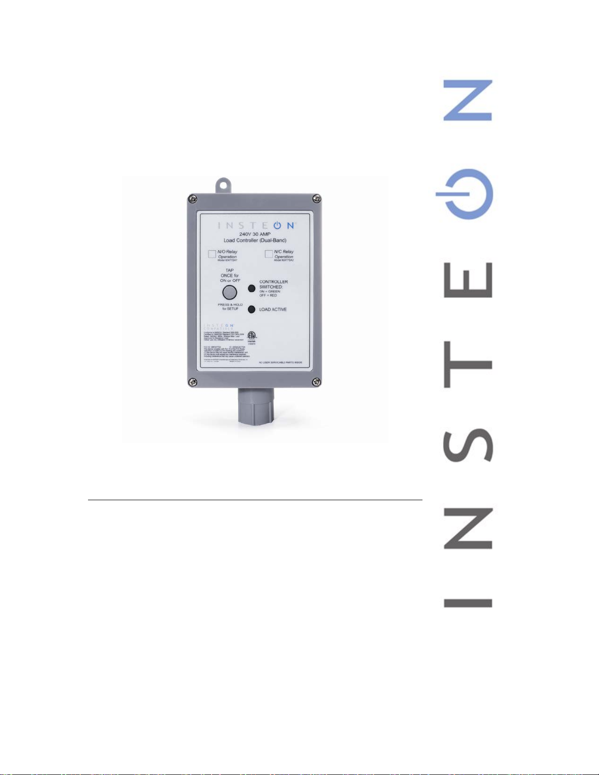
240V 30A Load Controller
Model :
2477SA1 (Normally Open)
INSTEON® 240V 30 Amp Load Cont roller (Dual-Band)
2477SA2 (Normally Closed)
Page 2

240V Load Controller Owner’s Manual
240V Load Controller Owner’s Manual
TABLE OF CONTENTS
ABOUT 240V LOAD CONTROLLER ........................................................................................................... 3
Key 240V Load Controller Features .......................................................................................................... 3
WHAT IS INSTEON? .................................................................................................................................... 4
INSTALLATION ............................................................................................................................................ 5
Tools You Will Need .................................................................................................................................. 5
Preparing to Install 240V Load Controller ................................................................................................. 5
Installing 240V Load Controller ................................................................................................................. 6
USING 240V LOAD CONTROLLER ............................................................................................................ 6
CONTROLLING 240V LOAD CONTROLLER FROM AN INSTEON CONTROLLER ................................ 7
Linking an INSTEON Controller to 240V Load Controller ......................................................................... 7
Unlinking 240V Load Controller from an INSTEON Controller .................................................................. 7
CONTROLLING INSTEON RESPONDERS FROM 240V LOAD CONTROLLER ...................................... 8
Linking 240V Load Controller to an INSTEON Responder ....................................................................... 8
Unlinking an INSTEON Responder from 240V Load Controller................................................................ 8
CREATING AN INSTEON SCENE ............................................................................................................... 9
ADVANCED FEATURES ............................................................................................................................. 9
Restoring Power to 240V Load Controller ................................................................................................. 9
Resetting 240V Load Controller to its Factory Default Settings ................................................................ 9
X10 PROGRAMMING OPTIONS ............................................................................................................... 10
Setting the X10 Address .......................................................................................................................... 10
Removing the X10 Address ..................................................................................................................... 10
ABOUT INSTEON ...................................................................................................................................... 10
Using Dual-Band INSTEON Devices to Upgrade Your Network ............................................................. 10
Important Note about INSTEON Networks; Split Single-Phase vs. 3-Phase Installation........................ 11
Further Enhancing Reliability .................................................................................................................. 11
ADDITIONAL RESOURCES ...................................................................................................................... 11
TROUBLESHOOTING ................................................................................................................................ 11
SPECIFICATIONS, CERTIFICATION, AND WARRANTY ........................................................................ 13
Specifications .......................................................................................................................................... 13
Certification .............................................................................................................................................. 13
FCC and Industry Canada Compliance Statement ................................................................................. 13
Limited Warranty ..................................................................................................................................... 14
Page 2 of 14
Page 3
240V Load Controller Owner’s Manual
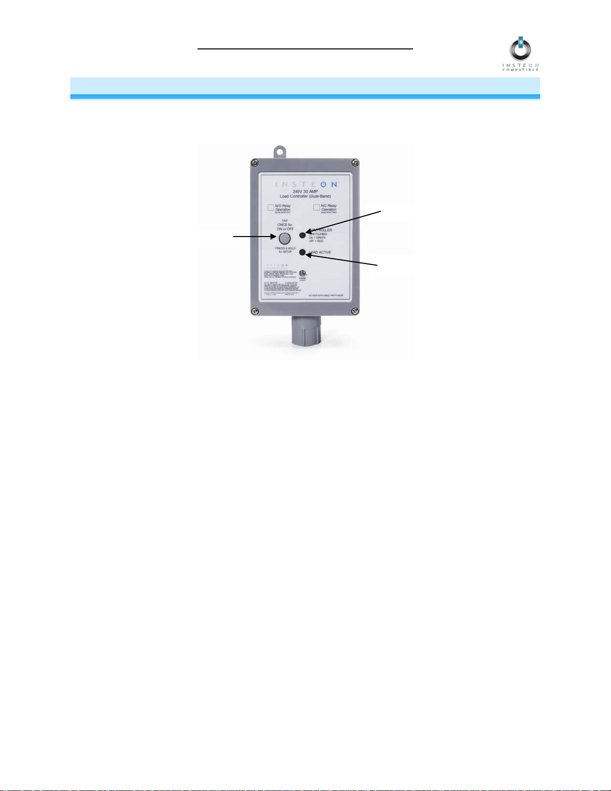
Set button
Status LED
Load Active LED
ABOUT 240V LOAD CONTROLLER
240V Load Controller lets you effic iently contro l the us e of heav y-duty appl iances to save energy and cut
down on utility costs. Remotely control your appliances that run on higher voltages, up to 30 Amps
(resistive loads only).
Key 240V Load Controller Features
• After installation, setup is easy – installs and links to other INSTEON devices in minutes
• Controls high-voltage appliances up to 240 Volts, 30 Amps, split-single phase (resistive loads only)
• Communicates simultaneously over both radio frequency (RF) and the power line
• Acts as an access point for RF-only devices
• Indicates INSTEON s etup mode activity and operatio nal states with a Load Active L ED, dual-color
Status LED and beeper
• Does not require a Neutral connection
• Set button functions as an On/Off toggle switch for the attached load
• Stores setup state in non-volatile memory so settings aren’t lost during power outages
• Two-year warranty
Page 3 of 14
Page 4

240V Load Controller Owner’s Manual
WHAT IS INSTEON?
Since its inception in 2 005, INST EON has bec om e the in dustr y gold standar d in home-control networking
technology, offering more reliability and flexibility than any other home management system on the
market. INSTEON is simple, r eliab le and af f or dable.
• Simple: each device takes just minutes to install.
• Reliable: every INST EON device works as a network repeater, ens uring your com mands will not
be lost.
• Affordable: INST EON c an be i ntegra ted int o an y number of devices easil y and at a ver y low cost.
An INSTEON home grows in value with each added INSTEON device, making life more
convenient, safe and fun.
How Does INSTEON Work?
What make s INSTEON the most reliable home autom ation network is its dual-mesh network . INSTEON
devices use both radio frequenc y (RF) signals and the hom e’s existing wiring to talk to eac h other. In an
INSTEON network, every INSTEON device also acts as a repeater, receiving and sending every
message to all other devices in the network. So by integrating more INSTEON devices you will strengthen
the network and ensure no commands will be lost.
No central controller or networking setup is required with an INSTEON network. Simply install your
devices and then use a series of button presses or t aps to link your devices together. T hroughout this
Owner’s Manual, you may s ee the term s “controller” or “responder.” T hese gener ic INST EON term s refer
to the components of an INSTEON scene, and are used on a scene-by-scene basis.
• Controller – sends INSTEON commands to other devices
• Responder – reacts to commands sent out by another INSTEON device
An INSTEON device may act as a controller, responder or sometimes both.
INSTEON networks are also extr emely secure. Each INSTEON device is assig ned a unique INSTEON
I.D., so unless neighbors or would-be hackers have access to your particular device’s INSTEON I.D., they
won’t be able to control your home, even if they are using similar products.
Page 4 of 14
Page 5

240V Load Controller Owner’s Manual
INSTALLATION
Tools You Will Need
• Screwdriver (to remove the cover of the junction box)
• Wire cutter/stripper
• Various tools to wall-mount 240V Load Controller
Preparing to Install 240V Load Controller
CAUTION
Read and understand these instructions before installing and retain them for future reference.
240V Load Controller is intended for installation in accordance with the National Electric Code and local regulations in
the United States or the Canadian Electrical Code and local regulations in Canada. Use indoors only. 240V Load
Controller is not designed nor approved for use on power lines other than 120V 60Hz, single phase. Attempting to
use 240V Load Controller on non-approved power lines may have hazardous consequences.
Prior to installing 240V Load Controller, please review the entire installation procedure and take the following
precautions:
• Because 240V Load Controller involves high voltage levels, it is recommended that installation be performed
only by a qualified electrician or by a homeowner who is extremely knowledgeable and familiar with
electrical circuitry. Please take an extra level of precaution when installing this device. If you have any
questions regarding installation, please consult an electrician.
• 240V Load Controller must be connected to a 2-pole tandem circuit breaker, rated for no more than 30
Amps. 240V Load Controller does not have over-current protection and therefore must be connected
through a circuit breaker.
• Be sure that you have turned off the circuit breaker or removed the fuse for the circuit you are installing
240V Load Controller in. Installing 240V Load Controller with the power on will expose you to dangerous
voltages.
• Connect only copper or copper-clad wire to 240V Load Controller
• 240V Load Controller may feel warm during operation. The amount of heat generated is within approved
limits and poses no hazards. To minimize heat buildup, ensure that the area surrounding the rear of 240V
Load Controller has adequate ventilation by clearing away excess insulation.
• Don’t use 240V Load Controller to control devices that preserve, maintain, or contribute to human or animal
safety or life support
• Don’t bury 240V Load Controller or any electrical cable or components connected to it. A buried power cord
may result in electrocution if improper cables are used or if digging occurs over the cable.
• Don’t allow vegetation to grow on or around 240V Load Controller
• Don’t install 240V Load Controller in a manner that allows water to accumulate around the unit
• Don’t attempt to open 240V Load Controller. The 240V Load Controller case is sealed and can’t be opened.
There are no user-serviceable parts inside.
• Each 240V Load Controller is assigned a unique INSTEON I.D., which is printed on the device’s lab el. It is
recommended that you prepare a list of all the devices you are installing, including their INSTEON I.D. and
their location (e.g., 01.F7.G5, Mike’s bedroom light). It is only necessary to know the INSTEON I.D.s if you
will be using optional automation software (such as Smarthome’s HouseLinc) to program and control your
devices. However, it will be helpful to have a list of your devices, should you choose to use automation
software later. Creating a list prior to installation will prevent you from needing to re-open all th e junction
boxes and fixtures to determine the INSTEON I.D.s.
IMPORTANT!
If you are not knowledgeable about and comfortable with electrical circuitry, you should have a qualified electrician
install 240V Load Controller for you. If you have any questions, please consult an electrician or call:
INSTEON Support Line
800-762-7845
Page 5 of 14
Page 6

240V Load Controller Owner’s Manual
240V Load Controller Model (SKU #)
Relay Status
Active Status LED
Open
Off
Closed
Solid green
Open
Off
Closed with load on
Solid green
Closed with load off
Off
Installing 240V Load Controller
1) At the circuit breaker or fuse panel, disable the circuit supplying power to the electrical junction box that is
wired to the appliance you wish to control with 240V Load Controller.
2) Remove the cover of the junction box and disconnect the two supply lines coming from the circuit breaker,
ensuring that you have ½” of bare wire on the ends.
3) Refer to the diagram below to properly connect 240V Load Controller to the load and junction box. The
Ground wire will not be connected to 240V Load Controller, so cap the Ground wire with a wire nut.
4) Ensure that all wire connectors are firmly attached and that there is no exposed copper except for the
Ground wire.
5) Enable power to the junction box from the circuit breaker or fuse panel.
6) Test that 240V Load Controller is working properly by pressing the Set button to toggle the load on and
then off.
USING 240V LOAD CONTROLLER
You can use the Set button on 240V Load Controller to toggle the load on and off
The 240V Load Controller Status LED will be solid green when the l oad is on and solid red when it is
off. See the following table for the Load Active LED status:
Normally Open Relay (#2477SA1)
Normally Closed Relay (#2477SA2)
Page 6 of 14
Page 7

240V Load Controller Owner’s Manual
CONTROLLING 240V LOAD CONTROLLE R FROM AN INSTEON CONTROLLER
Linking an INSTEON Controller to 240V Load Controller
To use 240V Load Con troller as a responder to an INSTEO N controller, follow thes e steps to link 240V
Load Controller and the controller together. Refer to the controller’s Owner’s Manual for detailed
instructions on how to properly install and link it to 240V Load Controller.
The following will work for the most common INSTEON devices:
1) Use the Set button on 240V Load Con troller to set th e load to the state you wish to activate fr om the
controller (turn it on if you wish it to be on or of f if you wish it to be of f when the controller activates
the scene)
2) Set the controller to linking m ode. (For m ost controllers, press and hold an On or Scene button f or 10
seconds or the Set button for 3 seconds.)
You will have 4 minutes to complete the next step before linking mode automatically times out.
3) Press and hold the Set button on 240V Load Controller until it double-beeps (3 seconds)
The 240V Load Controller Status LED
or solid red if it is off
4) Confirm that linking was successful by tapping the button you just linked to on the controller
240V Load Controller
will respond appropriately
will flash once and then turn on so lid gree n if the load is on
Unlinking 240V Load Controller from an INSTEON Controller
If you are going to disconti nue using 240V Load Cont roller, it is ver y important th at you unlink it from a ny
linked controllers. Other wise, the controller will retry any commands r epetitively, thus slowing do wn the
system.
The following will work for the most common INSTEON devices:
1) Set the controller to unlinking m ode. (For most controllers, press and hold an On or Scene button f or
10 seconds twice or the Set button for 3 seconds twice.)
You will have 4 minutes to complete the next step before unlinking mode automatically times out.
2) Press and hold the Set button on 240V Load Controller until it double-beeps (3 seconds)
The 240V Load Controller Status LED
or solid red if it is off
3) Confirm that unlinking was successf ul by tapping the button you just unlinked from on the controller
240V Load Controller
will no longer respond
will flash once and then turn on solid green if the load is on
Page 7 of 14
Page 8

240V Load Controller Owner’s Manual
CONTROLLING INSTEON RES P O NDERS FROM 2 4 0 V LOAD CONTROLLER
Linking 240V Load Controller to an INSTEON Responde r
To use 240V Load Controller as an INSTEON controller, follow these steps to link 240V Load Controller and an
INSTEON responder (the device you wish to control with 240V Load Controller) together. Refer to the
responder’s Owner’s Manual for detailed instructions on how to properly install and link it to 240V Load
Controller.
The following will work for the most common INSTEON devices:
1) At the responder, set it to the state you wish to be activated from 240V Load Cont roller (turn it on if you
wish it to be on, or off if you wish it to be off when 240V Load Controller activates the scene, set On-Levels,
etc.)
• If the responder is a multi-scene device (e.g., KeypadLinc), tap the Scene button you wish to
control until its LED illuminates
2) Set 240V Load Controller to linking mode by pressing and holding the Set button until it beeps (3 seconds)
The 240V Load Controller Status LED
You will have 4 minutes to complete the next step before linking mode automatically times out.
3) Press and hold the responder’s Set button for 3 seconds
240V Load Controller
solid red if it is off
4) Confirm that linking was successful by tapping the Set button on 240V Load Controller on and then off
will double-beep and its Status LED will turn on solid green if the load is on or
will begin blinking green
The responder
5) If you wish to link multiple responders to the same 240V Load Controller, repeat steps 1-4 with each
responder
will respond appropriately
Unlinking an INSTEON Responder from 240V Load Controller
If you are no longer going to use an INSTEON responder that has previously been linked to 240V Load
Controller, it is very important that you unlink it. Otherwise, 240V Load Controller will retry any commands
repetitively, thus slowing down the system.
The following will work on the most common INSTEON devices:
1) If the responder is a multi-scene device, tap the Scene button you wish to remove control from until its LED
illuminates
2) Set 240V Load Controller to linking mode by pressing and holding the Set button until it beeps (3 seconds)
The 240V Load Controller Status LED
3) Set 240V Load Controller to unlinking mode by pressing and holding the Set button until it beeps again (3
seconds)
The 240V Load Controller Status LED
You will have 4 minutes to complete the next step before unlinking mode automatically times out.
4) Press and hold the responder’s Set button for 3 seconds
240V Load Controller
solid red if it is off
5) Confirm that unlinking was successful by tapping the Set button on 240V Load Controller on and then off
The responder
will no longer respond
will double-beep and its Status LED will turn on solid green if the load is on or
will begin blinking green
will begin blinking red
Page 8 of 14
Page 9

240V Load Controller Owner’s Manual
CREATING AN INSTEON SCENE
INSTEON scenes let you ac tivate dram atic li ghting m oods w ith the pr ess of j ust one button. F or ex am ple,
you can set all the lights in a scene to dim to 50% or turn c ertai n lights o n whil e turnin g other s of f, all with
the tap of a button on a controller.
INSTEON scenes are ver y easy to set up – just link more than one responder to the same On/Off or
Scene button on a controller. T hen, when you press any of the linked buttons on the controller, a ll of the
INSTEON devices linked in the scene will respond as a group.
ADVANCED FEATURES
Restoring Power to 240V Load Controller
240V Load Controller store s all of its settings, suc h as links to other INST EON devices, with non-volatile
memory. Because set tings are saved in t his non-volatile memory, the y will not be lost in the ev ent of a
power failure.
Resetting 240V Load Controller to its Factory Default Se ttings
The factory reset procedur e will clear 240V Load Controller of all INSTEO N links and progr ammed X10
addresses.
NOTE: Depending on the location of your circuit breaker or fuse panel, you might need to recruit
someone to help you perform the following procedure.
1) If you are us ing a controller to control 240V Load Controller , be sure to unlink it from the controller.
See Unlinking 240V Loa d Contr o ller from an INSTEON Controller.
2) If you are using 240V Load Contro ller to control any INSTEO N devices, unlink those devices from
240V Load Controller. See Unlinking an INSTEON Responder from 240V Load Controller.
3) At the circuit breaker or fuse panel, disab le the circuit suppl ying power to the junction box for about
10 seconds
4) While holding down the Set butt on on 24 0V L oad C o nt r oller, re-enable power to t he j unction box from
the circuit breaker or fuse panel, making sure not to let go of the Set button
240V Load Controller
5) Continue to hold down the Set button for 3 seconds and then release
A few seconds after you release the button, 240 V Load Co ntroller
will turn on solid green
LED
The load
will turn on
will beep
will double-bee p and its St atus
Page 9 of 14
Page 10

240V Load Controller Owner’s Manual
X10 PROGRAMMING OPTIONS
240V Load Controller is X 10 ready, meaning that it can res pond to X10 commands from X 10 controllers
and it can send com mands to X10 d evices. However, to o perate 2 40V Load C ontroller in X10 mode, you
must first set up an X10 address. As it ships from the factor y or after a factory reset proc edure, 240V
Load Controller will not have an X10 address set up.
Setting the X10 Address
You must complete the following before 240V Load Controller will respond to X10 commands:
1) Set 240V Load Controller to linking mode by pressing and holding the Set button until it beeps (3
seconds)
The 240V Load Controller
You will have 4 minutes to complete the next step before linking mode automatically times out.
2) Using an X10 controller, send the X10 address you want to assign followed by the ON command
three times
For example, to assign the address A1, you would send “A1 ON A1 ON A1 ON.”
3) Once 240V Load Controller has received the preceding sequence three times, it will exit linking mode
240V Load Controller
or solid red if it is off
will begin blinking green
will double-be ep and its Status LED will turn o n solid green if the l oad is on
Removing the X10 Address
If you are no longer go ing to control 240 V Load Controller with an X10 address , it is very important tha t
you unlink it, because ot herwise 240V Load Contro ller will respond to the X10 c ommand and m ay cause
the device to turn on by itself.
1) Set 240V Load Controller to linking mode by pressing and holding the Set button until it beeps (3
seconds)
The 240V Load Controller
2) Set 240V Load Controller to unlinking mode by pressing and holding the Set button until it beeps
again (3 seconds)
The 240V Load Controller
You will have 4 minutes to complete the next step before unlinking mode automatically times out.
will begin blinking green
will begin blinking red
3) Using an X10 controller, send the X10 address you want to remove, followed by the ON comm and
three times
For example, to remove the address A1, you would send “A1 ON A1 ON A1 ON.”
4) Once 240V Load Controller has received the preceding sequence thr ee times, it will exit unlinking
mode
240V Load Controller
or solid red if it is off
will double-be ep and its Status LED will turn o n solid green if the l oad is on
ABOUT INSTEON
Using Dual-Band INSTEON Devices to Upgrade Your Network
What are phases?
Page 10 of 14
Page 11

240V Load Controller Owner’s Manual
Problem
Possible Cause
Solution
The majority of single-family homes in North America have two phases (or “legs”) of 110 Volts coming into their
electricity panels. From the panel, they are distributed throughout the home, providing power to outlets and wall
switches. These phases come together in some parts of the home to provide 220 Volts of power to large
appliances, such as an electric oven or pool pump.
Why do I need to bridge these phases?
Single-band power line devices send commands via the home’s electricity, but only on a single phase. If the
command is intended for a device on the opposite phase, there is a good chance the command will go
unnoticed. Installing dual-band INSTEON devices, such as Access Points (#2443), on each phase will allow for
devices to communicate between the two phases via RF.
Dual-band INSTEON devices embody the full potential of a true INSTEON mesh network. Taking the power
line band signal and working in conjunction with the RF band signal, its dual-band function plays out in two
ways:
• Phase bridger – a receiver of commands, reacting to and translating signals sent from one power
phase to the opposite via RF
• Signal repeater – a participant in an INSTEON network, repeating commands intended for other
devices whether those commands are generated from RF or power line-only devices. To ensure
reliability, every INSTEON device confirms that it has received a command. If a controller does not
receive this confirmation, it will automatically retransmit the command up to five times.
While us ing at least one dual-band device is required when using an RF-only device, at least two dual-band
devices are recommended to ensure reliable communication across two-phase home wiring systems. For
larger applications, it is recommended to install at least one dual-band device for every 750 – 1,000 square
feet.
Search for dual-band INSTEON devices at: www.smarthome.com/dualband
Important Note about INSTEON Networks; Split Single-Phase vs. 3-Phase Installation
For the best INSTEON network performance, be sure you have properly installed at least two dual-band
INSTEON devices. INSTEON has only been officially tested in a split single-phase residential environment but
has been known to work in many 3-phase systems, where three dual-band devices are used (one on each
phase). However, due to the potential complexity of its troubleshooting, the INSTEON Support Line is unable to
support INSTEON in 3-phase environments.
Further Enhancing Reliability
As signals travel via the power line or RF throughout the home, they naturally become weaker the farther they
travel. The best way to overcome weakened signals is to increase the coverage of the mesh network by
introducing more INSTEON devices.
It is possible that some audio-video devices, computers, power strips, or other electrical equipment may
attenuate INSTEON signals on the power line. You can temporarily unplug suspected devic es to test whether
the INSTEON signal improves. If it does, then you can plug in filters that will permanently fix the problem.
ADDITIONAL RESOURCES
Find home automation solutions, helpful tips, interactive demos, user forums, and more at the Smarthome
Learning Center: www.smarthome.com/learningcenter.html
TROUBLESHOOTING
Page 11 of 14
Page 12

Problem
Possible Cause
Solution
Check the attached load to ensure all connections
are tight and no bare wires are exposed.
The controller may have
Controller from it.
Unlink any unused responders from the controller.
eliminate unnecessary links.
Add additional INSTEON devices or move around
as INSTEON network repeaters.
240V Load Controller
installed it.
Disable power at the circuit breaker for 10 seconds
and then restore power.
If the above doesn’t work, perform a factory reset.
Default Settings.
The Status LED on
240V Load Controller is
not turning on and
won’t control the load.
240V Load Controller Owner’s Manual
Make sure the circuit breaker is turned on.
240V Load Controller may
not be getting power.
Check the junction box wires to ensure all
connections are tight and no bare wires are exposed.
The load is not being
controlled after I’ve
linked 240V Load
Controller to a
controller.
240V Load Controller is
taking a long time to
respond to a controller.
The load turned on by
itself.
doesn’t respond to X10
address A1 after I
The load is not getting
power.
been reset without first
unlinking 240V Load
The controller may be
sending commands to a
responder that is no longer
in use. Commands for the
unused responder are
being resent and loading
down the signal.
The INSTEON signal may
be too weak.
Another controller, a timer,
or stray X10 signals
triggered 240V Load
Controller.
240V Load Controller does
not have an X10 address
set up at the factory.
Make sure the load’s built-in switch is in the on
position.
Relink 240V Load Controller to the controller. See
Linking an INSTEON Controller to 240V Load
Controller.
HINT: If you are using home automation software,
you can easily check scene membership and
If the above doesn’t work, perform a factory reset on
the controller.
existing INSTEON devices. All INSTEON devices act
Perform a factory reset. See Resetting 240V Load
Controller to its Factory Default Settings.
Set up an X10 address. See Setting the X10
Address.
The controller can turn
off 240V Load
Controller, but it does
not turn on when I send
an ON command from
the controller.
240V Load Controller is
locked up.
If you have tried these solutions, reviewed this Owner’s Manual, and still cannot resolve an issue you are
having with 240V Load Controller, please call:
240V Load Controller may
be linked at its off state.
A surge or excessive noise
on the power line may have
glitched it.
Relink 240V Load Controller to your controller, while
the load is on. See Linking an INSTEON Controller to
240V Load Controller.
See Resetting 240V Load Controller to its Factory
INSTEON Support Line
800-762-7845
Page 12 of 14
Page 13

240V Load Controller Owner’s Manual
SPECIFICATIONS, CERTIFICATION, AND WARRANTY
Specifications
View specifications for 240V Load Controller (Normally Open) at: www.smarthome.com/2477SA1.html
or 240V Load Controller (Normally Closed) at: www.smarthome.com/2477SA2.html
Certification
This product has been thorough ly tested b y ITS ETL SEMKO, a nationall y recognized in dependent thirdparty testing laborator y. The North Am erican ET L Lis ted m ark s ignifies tha t the device has been tested to
and has met the requirements of a widely recognized consensus of U.S. and Canadian device safety
standards, that the manufacturing site has been audited, and that the manufacturer has agreed to a
program of quarterly factory follow-up inspections to verify continued conformance.
FCC and Industry Canada Compliance Statement
This device complies with FCC Rules Part 15 and Industry Canada RSS-210 (Rev. 7). Operation is
subject to the following two conditions:
(1) This device may not cause harmful interference, and
(2) This device must accept any interference, including interference that may cause undesired
operation of the device.
Le present appare il est conforme aux CNR d'Industrie Canada applicables aux apparei ls radio exempts
de licence. L'exploitation est autorise aux deux conditions suivantes:
(1) l'appareil ne doit pas produire de brouillage, et
(2) l'utilisateur de l'a ppareil doit accepter tout br ouillage radiolectriq ue subi, mme si le brouillag e est
susceptible d'en compromettre le fonctionnement.
The digital cir cuit r y of th is device has bee n tested and found to com pl y with the lim its for a Class B digital
device, pursuant to Part 15 of the FCC Rules. T hese l im its ar e designed to pro vide r eason able pr otecti on
against harmful interfer ence in residential installations . This equipment generate s, uses, and can radiate
radio frequency energy and, if not installed and used in accordance with the instructions, may cause
harmful interference to ra dio and television reception. However, there is not guar antee that interference
will no occur in a particul ar installat ion. If this devic e does c ause suc h interfer ence, which can be ver ified
by turning the de vice off and on, the user is encouraged to e liminate the interf erence by one or m ore of
the following measures:
• Re-orient or relocate the receiving antenna of the device experiencing the interference
• Increase the distance between this device and the receiver
• Connect the device to an AC outlet o n a circuit different from the one that supplies power to the
receiver
• Consult the dealer or an experienced radio/TV technician
WARNING: Changes or modifications to t his device not expr essly approved by the par ty responsible f or
compliance could void the user’s authority to operate the equipment.
Page 13 of 14
Page 14

240V Load Controller Owner’s Manual
Limited Warranty
Seller warrants to the original consumer purchaser of this product th at, for a period of two years f rom the
date of purchase, th is product will be free f rom defects in material and workmanship and will perf orm in
substantial conform ity to the description of the produ ct in this Owner’s Manual. This warranty shall not
apply to defects or er rors caused b y misuse or neg lect. If the product is found to be defec tive in mater ial
or workmanship, or if the product do es not p erf orm as warranted ab ove dur ing the warra nty peri od, Sel ler
will either repair it, re place i t, or ref und th e purchas e pric e, at its opt ion, up on rec eipt of the prod uct at the
address below, postage pr epaid, with proof of the date of purchas e and an explanation of the defect or
error. The repair, replacement, or refund that is provided for above shall be the full extent of Seller’s
liability with respect to this product. For repair or replacement during the warranty period, call the
INSTEON Support Line at 800-762-7845 with the Model # and Revision # of the device to receive an
RMA# and send the product, along with all other required materials to:
Smarthome, Inc.
ATTN: Receiving Dept.
16542 Millikan Ave.
Irvine, CA 92606-5027
Limitations
The above warranty is in lieu of and Seller disclaims all other warranties, wheth er oral or written, express
or implied, including any warranty or merchantability or fitness for a particular purpose. Any implied
warranty, including an y warranty of merchantability or fitness for a particular pur pose, which ma y not be
disclaimed or supplanted as provided above shall be limited to the two-year of the express warranty
above. No other representation or claim of any nature by any person shall be binding upon Seller or
modify the terms of the above warranty and disclaimer.
Home automation devices have the risk of failure to operate, incorrect operation, or electrical or
mechanical tam pering. For optimal use, manuall y verify the device state. An y home automation device
should be viewed as a convenience, but not as a sole method for controlling your hom e.
In no event shall Seller be liable for special, incident al, consequential, or other dam ages resulting from
possession or use of this device, including without limitation damage to property and, to the extent
permitted by law, personal injury, even if Seller knew or should have known of the possibility of such
damages. Some states do not allow limitations on how long an implied warranty lasts and/or the exclusion
or limitation of dam ages, in which c ase the abo ve lim itations and/or exclus ions m ay not app l y to you. You
may also have other legal rights that may vary from state to state.
INSTEON Technology Patent
U.S Patent No. 7,345,998, International patents pending
© Copyright 2011
Smarthome, 16542 Millikan Ave., I rvine, CA 92606, 800-762-7845, www.smarthome.com
Rev 04-28-2011
Page 14 of 14
 Loading...