

Page 1
SwitchLinc™ On/Off (Dual-Band)
INSTEON® Remote Control Switch
Owner’s Manual (#2477Sxx)
Page 1 of 18 2477S - Rev: 1/21/2014 7:27 AM
Page 2

SwitchLinc On/Off – Features and Benefits ............................................................................................. 3
Features..................................................................................................................................................... 3
What’s in the Box? ..................................................................................................................................... 3
Installation ................................................................................................................................................... 4
Identifying the Electrical Wires in Your Home ........................................................................................... 4
Tools Needed ............................................................................................................................................ 4
Installing SwitchLinc in Circuits with 1 Switch ........................................................................................... 5
Installing SwitchLinc in Circuits with 2 Switches/3-W ay Circuit ................................................................. 8
Using SwitchLinc ........................................................................................................................................ 8
LEDs .......................................................................................................................................................... 8
Using SwitchLinc ....................................................................................................................................... 8
Setup ............................................................................................................................................................ 8
INSTEON Controllers, Responders and Links .......................................................................................... 8
Making SwitchLinc an INSTEON Responder ............................................................................................ 8
Making SwitchLinc an INSTEON Controller (Adding a Responder).......................................................... 9
Groups (Synchronizing Devices) ............................................................................................................... 9
Scenes ..................................................................................................................................................... 10
Removing SwitchLinc as an INSTEON Responder ................................................................................ 10
Removing SwitchLinc as an INSTEON Controller (Removing a Responder) ......................................... 11
Adding Multiple Responders ................................................................................................................... 11
Removing Multiple Responders .............................................................................................................. 11
Changing LED Brightness ....................................................................................................................... 12
Error Blinking ........................................................................................................................................... 12
Air Gap (Removing Power)...................................................................................................................... 12
Using SwitchLinc LED as an INSTEON Traffic Indicator ........................................................................ 12
Factory Reset .......................................................................................................................................... 12
Phase Detect Beacon ................................................................................................................................ 12
X10 Setup ................................................................................................................................................... 13
Adding X10 Address ................................................................................................................................ 13
Removing X10 Address ........................................................................................................................... 13
Other X10 Setup ...................................................................................................................................... 13
Change Paddle and LED Colors .............................................................................................................. 14
Specifications ............................................................................................................................................ 14
Troubleshooting ........................................................................................................................................ 16
Certification and Warranty ....................................................................................................................... 18
Certification .............................................................................................................................................. 18
FCC and Industry Canada Compliance Statement ................................................................................. 18
Limited Warranty ..................................................................................................................................... 18
Limitations ............................................................................................................................................ 18
Page 2 of 18 2477S - Rev: 1/21/2014 7:27 AM
Page 3
In the Box
Tools Needed
Optional Accessories
SwitchLinc On/Off
Slotted and Phillips screwdrivers
INSTEON app
Quick Start Guide
Wire cutter/stripper
SmartLinc Hub
2 screws and 4 wire nuts
Voltage meter
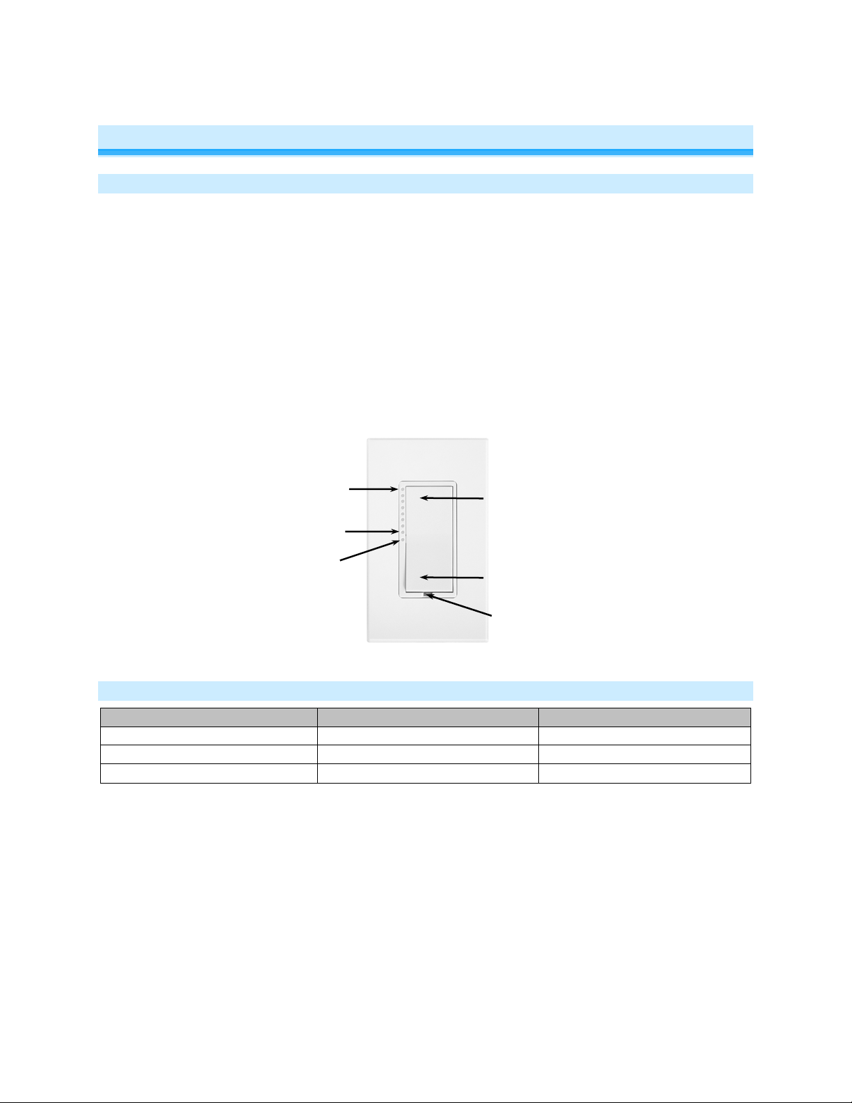
Setup LED
Set button (push)
On LED
Tap for On
Tap for Off
Off LED
About SwitchLinc On/Off Dual-Band
Features and Benefits
• Controls virtually all load types
• Can be remotely controlled from any INSTEON controller
• 100-277VAC capable (can be used to control 277V commercial lighting circuits)
• 17A resistive capacity (100-277VAC)
• 1,800 Watt incandescent capacity (100-277VAC)
• 1 HP motor (at 120VAC only)
• 10A ballast (100-277VAC)
• 50/60 Hz electric ity automaticall y detected
• Beeper and dual-color LED for easy setup and linking.
• Dimmable status LED acts as a nightlight when switch is off
• Responds to and sends X10 commands
• Wires in like a standard wall switch (neutral connection required)
• Supports SwitchLinc wireless 3-way and 4-way circuits
• Two-year warranty
Air Gap (pull out)
What’s in the Box?
Page 3 of 18 2477S - Rev: 1/21/2014 7:27 AM
Page 4

electrical circuitry, have a qualified electrician install the product for you.
Cautions and Warnings
CAUTIONS AND WARNINGS
Read and understand these instructions before installing and retain them for future reference.
This product is intended for installation in accordance with the National Electric Code and local regulations in the United States or
the Canadian Electrical Code and local regulations in Canada. Use indoors only. This product is not designed or approved for
use on power lines other than single-phase voltages between 100V and 277V, 50/60Hz. Attempting to use this product on nonapproved powerlines may have hazardous consequences.
Recommended installation practices:
• Use only indoors or in an outdoor-rated box.
• Be sure that you have turned off the circuit breaker or removed the fuse for the circuit into which you are installing this
product. Installing this product with the power on will expose you to dangerous voltages.
• The wires connecting SwitchLinc to the incoming power must be protected by a fuse or circuit breaker of 20A or less.
• Connect using only copper or copper-clad wire.
• This product may feel warm during operation. The amount of heat generated is within approved limits and poses no
hazards. To minimize heat buildup, ensure the area surrounding the rear of this product is as clear of clutter as possible.
• To reduce the risk of overheating and possible damage to other equipment, do not use this product to control loads in
excess of the specified maximum(s) or install in locations with electricity specifications which are outside of the product’s
specifications. If this device supports dimming, please note that dimming an inductive load—such as a fan or transformer—
could damage the dimmer, the load-bearing devic e or bot h. If the manufact urer of the load-bearing devi c e does not
recommend dimming, use a non-dimming INSTEON on/off switch. USER ASSUMES ALL RISKS ASSOCIATED WITH
DIMMING AN INDUCTIVE LOAD.
Identifying the Electrical Wires in Your Home
• Line – usually black, may also be called Hot, Live or Power, carries 100-277VAC electrici t y into the wall box.
• Neutral – usually a white wire bundle, commonly daisy-chained from box to box.
• Load – usually black, from a separate cable jacket.
• Ground – Bare copper wire or metal fixture (if grounded).
If installing in a commercial application, please follow standard commercial wiring practices.
IMPORTANT!
• Each INSTEON product is assigned a unique INSTEON I.D., which is printed on the product’s label. Please take note of
each product’s I.D. for future reference.
• If you have any difficulties or questions, consult an electrician. If you are not knowledgeable about or comfortable with
Tools Needed
• Flathead screwdriver • Phillips screwdriver
• Wire cutter/stripper • Voltage meter
Page 4 of 18 2477S - Rev: 1/21/2014 7:27 AM
Page 5
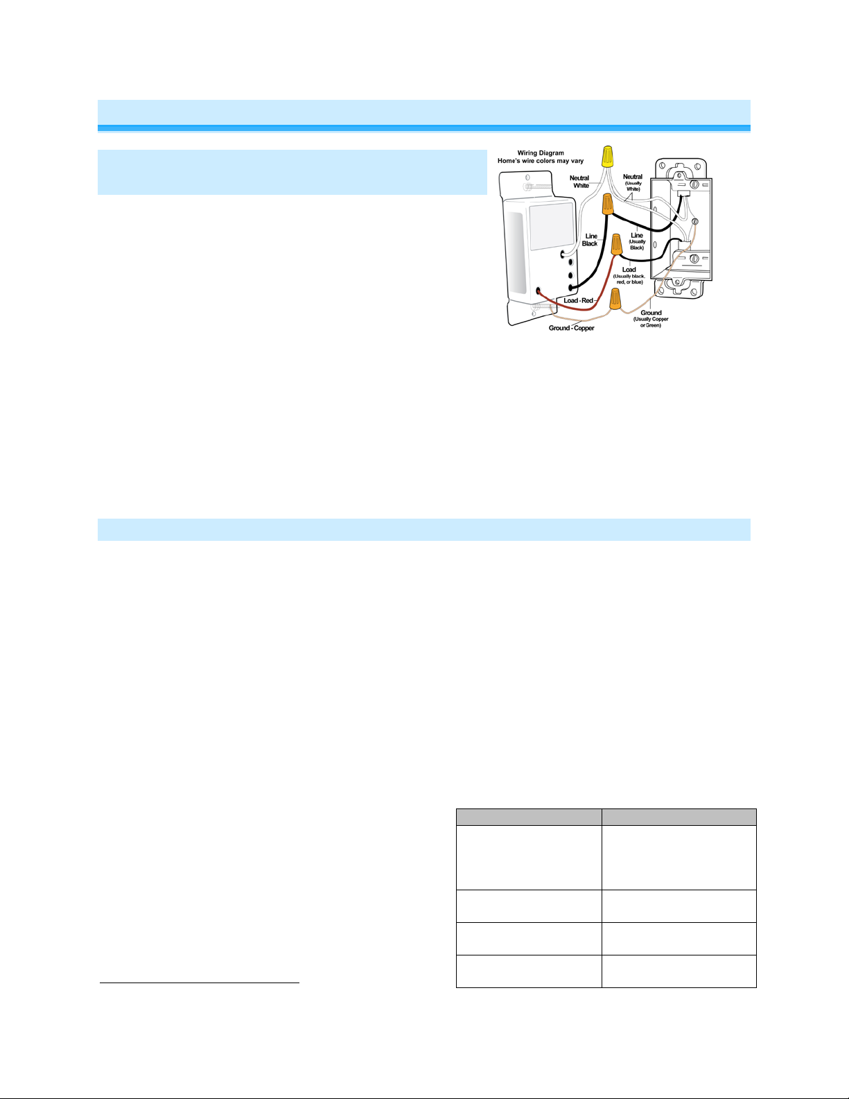
Installation
SwitchLinc Wire
Wall Box Wires
Ground
green screw)
Neutral
(commonly white)
Load
(connected to light)
Line
(120V to Ground)
Installation – Circuit with 1 Switch (a.k.a. 2way circuit)
1) At electrical panel, turn off circuit breaker(s) and/or
remove fuse(s) feeding wall box. Verify that the power is
off before continuing
2) Remove wallplate from the switch. Unscrew switch and
gently pull out
3) Disconnect wires from switch
4) Turn on power
5) Use a voltage meter to identify the line and load wires
connected to the switch
6) Identify neutral and ground wires
7) Turn off power
8) Connect wires as per table/diagram (confirm firm attachments with no exposed wire)
9) With LEDs on left, gently place SwitchLinc into wall box and screw into place
10) Turn on power
SwitchLinc and its connected load will turn on
11) Verify SwitchLinc is working properly by tapping Switc hLinc on and off
SwitchLinc and its connected load will turn on and off
12) Reinstall wallplate
3
Installation – Circuit with 2 Switches (a.k.a. 3-way circuit)
Circuits with 2 switches are called 3-way circuits. Both switches in a 3-way circuit need to be replaced by
SwitchLincs (and/or other INSTEON devices).
1) Turn off circuit breaker(s) and/or remove fuse(s) feeding wall boxes (verify that power is off)
2) Pull both switches from their wall boxes (each switch will have no less than 3 wires)
3) Remove wires from existing switches
4) Make sure wires are safely separated from each other and turn power back on
5) Using a voltage meter measure each wire to ground in both boxes until you find the single wire
supplying 120V (line)
a. We will now refer to that location as Box 1
b. The other box will have the load wire. That will be Box 2
6) Turn power back off
In Box 1 (Line box)
7) Connect bare SwitchLinc ground to bare ground wire or ground screw in wall box
8) Connect SwitchL in c white wire to neutral wire(s) in
wall box (usually white)
9) Using a wire nut, cap SwitchLinc red wire.
10) Connect SwitchLinc black wire to Line w ir e in w al l
Bare copper
box (usually black) along with one traveler wire
running between boxes. (pr ef er abl y black ) Note
color of this traveler – it will carry 120V/line voltage
White
to Box 2.
11) Cap unused traveler
Red
3
If the wires cannot be detached by unscrewing them, cut the wires where they enter the switch, then strip ½” of insulation off the ends
Black
(commonly bare
copper, green wire or
Page 5 of 18 2477S - Rev: 1/21/2014 7:27 AM
Page 6
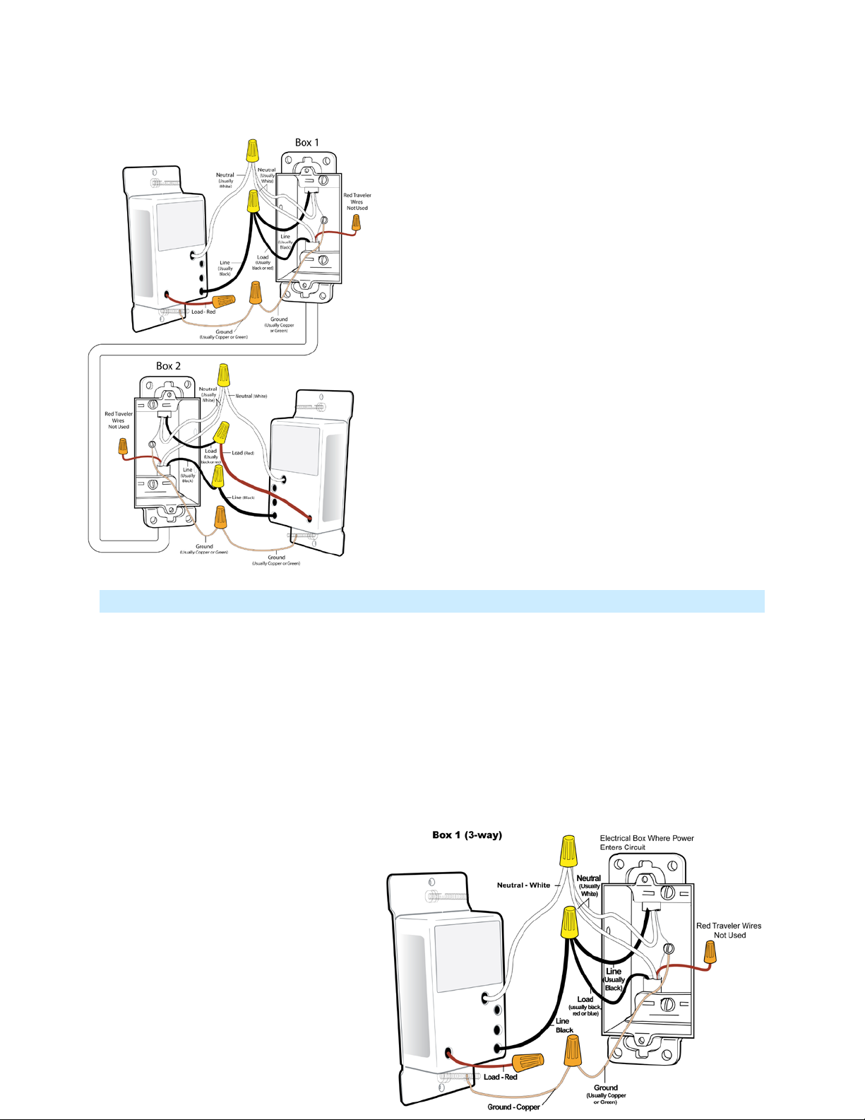
In Box 2 (Load box)
12) Connect SwitchLinc bare wire to bare ground wire or
ground screw in wall box
13) Connect SwitchLinc white wire to neutral wire(s) in wall
box (usually white)
14) Connect SwitchLinc red wire to load wire
15) Connect SwitchLinc black wire to same color traveler
from Box 1 carrying Line (usually black)
16) Cap unused traveler wire
17) With LEDs on left, gently place SwitchLincs into their
wall boxes and screw in place
18) Turn power back on
SwitchLincs and connected load will turn on (only
SwitchLinc in Box 2 will operate load)
19) Add both SwitchLincs to a group. See “Groups”
20) Verify both SwitchLincs are working properly by
tapping on and off on each SwitchLinc
Both SwitchLincs and the connected load will
remain in synch
21) Reinstall wallplates
Installation – Circuit with 3 (or more) Switches
Circuits with 3 or more switches are called 4-way (or 5-way, etc.) All switches in 3-way/4-way circuits
need to be replaced by INSTEON devices.
1) Turn off circuit breaker(s) and/or remove fuse(s) feeding wall boxes (verify that power is off)
2) Pull all three switches from their wall boxes (4-way (and higher) switches have 3 or 4 wires)
3) Remove wires from existing switches
4) Make sure wires are safely separated from each other and turn power back on
5) Using a voltage meter measure each wire to ground in all three boxes until you find the single wire
supplying 120V (line)
a. We will now refer to that location as Box 1
b. The location having 2 sets of matching pairs of wires will be Box 2 (i.e. 2 reds and 2 blacks, or
other matching colors). These are 2 travelers from Box 1 and 2 travelers leading to Box 3
c. The last box will have the load w ire. That will be Box 3
6) Turn power back off
In Box 1 (Line box)
7) Connect SwitchLinc bare wire to
ground
8) Connect SwitchL inc w hite wire to
neutral
9) Cap SwitchLinc red wire
10) Connect SwitchLinc black wire to line
plus one traveler (preferably black)
Page 6 of 18 2477S - Rev: 1/21/2014 7:27 AM
Page 7

and note color of traveler you are using as this will carry line voltage to Box 2
11) Cap unused traveler wire
In Box 2 (Traveler box)
12) Connect SwitchLinc bare wire to ground
13) Connect Swit c hL in c white wire to neutral
4
14) Cap SwitchLinc red wire
15) Connect SwitchLinc black wire to same color
traveler from Box 1 that you connected to line
along with same color traveler wires leading to
Box 3
16) Cap the last u nused tr av el e r wire(s)
In Box 3 (Load box)
17) Connect SwitchLinc bare wire to ground
18) Connect Swit c hL in c white wire to neutral
19) Connect SwitchLinc red wire to load
20) Connect SwitchLinc black wire to line traveler
from Box 2 (Line traveled from Box 1 through 2 into
3 usually black)
21) Cap unused traveler wire
22) With LEDs on left, gently place SwitchLincs into
wall boxes and screw in place
23) Turn power back on
SwitchLincs and connected load will
turn on
24) Add all SwitchLincs to a group. See “Groups ”
22) Verify all SwitchLincs are working properly by
tapping each on and off
All SwitchLincs and the connected load
will remain in synch
25) Reinstall wallpl ates
4
If neutral is not available in this box; use other unused traveler from Box 1 to carry neutral to Box 2. Label and mark any differently colored wire being connected to neutral with
a piece of white tape to flag it as neutral.
Page 7 of 18 2477S - Rev: 1/21/2014 7:27 AM
Page 8

Local Control
Paddle
Tap
Press and hold
Double-tap
LEDs
Controller
Responder
Link
SwitchLinc
Controller
Follow these instructions to control the connected light/loa d (as we ll as any responders) from the
SwitchLinc paddle.
Top
Bottom
On
Off
On
Sends brighten to responders
Off
Sends dim to responders
Sends fast-on to responders
Sends fast-off to responders
On
Off
Top LED on
Bottom LED on
Setup
SwitchLinc is fully configurable using home automation software (such as HouseLinc). Software will make
it easy to set up controller-responder links, synchronize groups, arrange multi-device scenes and adjust
device properties.
INSTEON Controller s, R es pon der s and Li nk s
Let’s define a few terms:
• The device initiating an INSTEON message is called a controller.
• The device receiving the INSTEON message is called a responder.
• The association between the controller and responder is called a link.
Please note that a link is one way. If you wish to have two-way control, simply repeat the link setup
process from the responder to the controller. Most INSTEON devices can store hundreds of links, and
each individual link can have its own properties (e.g., 50% brightness at a 4-second ramp rate).
Furthermore, a controller can simultaneously control from one to hundreds of responders using groups
and scenes.
Make SwitchLinc a Responder
Configure using home automation software (such as HouseLinc) or follow the steps below to control
SwitchLinc from another INSTEON device.
1) Press and hold controller button until it beeps.
Controller LED will start blinking.
10
If the controller does not have a beeper, wait until its LED begins blinking.
Page 8 of 18 2477S - Rev: 1/21/2014 7:27 AM
10
(Responder)
Page 9

2) Tap SwitchLinc on (or off if desired for the link).
SwitchLinc
Responder
Load will be on (or off).
3) Press and hold SwitchLinc Set button until it double-beeps.
Controller LED will stop blinking.
Unit will double-beep.
11
4) Test by tapping controller button on and off.
SwitchLinc will respond appropriately.
Note: The link just created is one-way. See Make SwitchLinc an IN STEON Controller to add another link
to create a two-way link and keep the two products in synch.
Make SwitchLinc a Controller
Configure using home automation software (such as HouseLinc) or follow the steps below to control an
INSTEON device from SwitchLinc.
1) Press and hold Switc hLinc set button until it beeps.
SwitchLinc LED will start blinking green.
2) Adjust the responder(s) to the state you want when scene
is activated from SwitchLinc (e.g., 50%, 25% or even off).
3) Press and hold responder Set button until it double-beeps
(or until its LED flashes).
SwitchLinc LED will stop blinking.
Responder LED will stop blinking and unit will double-
beep
4) Test by tapping SwitchLinc paddle on and off.
Responder will toggle between the scene on-level and off
5) If you wish to add another responder, repeat steps 1-5 (or see Add Multiple Responders).
Notes:
- The link just created is one-way. See Make S witchLin c an INSTEON Responder to add another link
to create a two-way link and keep the two products in synch.
- If you wish the SwitchLinc load to be of f when the link is activated (such as f or an “all-off” scene),
turn off the load in step 2.
(Controller)
Groups (Synchronizing Devices)
Devices in a group share all the same settings (e.g., on-level, ramp rate). This keeps all group members
synchronized. Every device in a group is both a controller of and responder to all the other devices. The
most common example of a group is a 3-way lighting cir c uit with 2 switches, such as switches at either
end of a hallway.
Configure using home automation software (such as HouseLinc) or follow the steps below to set up a 3way circuit with two switches. For simplicity, we will assume that the desired group level is on.
Example: Set up a 3-way circuit with two switches, A and B
1) Turn A and B on.
2) Press and hold A set button until it beeps (or LED blinks).
A’s LED will start blinking green.
3) Press and hold B set button until it double-beeps (or LED flashes).
B will double-beep.
A will double-beep and its LED will stop blinking.
4) Press and hold B set button until it beeps (or LED blinks).
11
Most models
Page 9 of 18 2477S - Rev: 1/21/2014 7:27 AM
Page 10

B LED will start blinking green.
5) Press and hold A set button until it double-beeps (or LED flashes).
A will double-beep.
B will double-beep and its LED will stop blinking.
6) Test the group by controlling the Load from A and then B.
The load, A’s LED and B’s LED will all remain in synch.
Scenes
INSTEON scenes allow a controller to simultaneousl y activate multiple responders at individual preprogrammed levels. Home automation software (such as HouseLinc) is helpful in setting up and
maintaining scenes, especially larger ones. Configure scenes using software or follow the steps below.
Example: Create a scene with a single controller and SwitchLinc as a responder/member
1) Press and hold controller Set button until it beeps.12
Controller LED will start blinking.
2) Tap controller Set button.
Controller will beep.
Controller LED will double-blink.
3) Tap SwitchLinc on (or off if desired for the link).
Load will be on (or off).
4) Press and hold SwitchLinc Set button until it double-beeps.
Controller LED will continue blinking and unit will double-beep.
5) For each additional scene member:
a. Adjust device to desired scene state.
b. Press and hold it s Set button.
6) Tap controller Set button.
Controller LED will stop blinking.
7) Test by tapping controller button on and off.
SwitchLinc and other scene responders will all respond appropriately.
Remove SwitchLinc as a Responder
If you no longer want a controller button to control SwitchLinc, configure using home automation software
(such as HouseLinc) or follow the steps below to remove SwitchLinc’s responder link.
Note: If you ever wish to uninstall SwitchLinc, it is important that you remove all SwitchLinc responder
links. Otherwise, controllers will repetitively retry commands, creating network delays.
13
1) Press and hold controller Set button until beep.
LED will start blinking.
2) Press and hold controller Set button until it beeps again.
LED will continue blinking.
3) Press and hold SwitchLinc Set button until double-beep.
Controller LED will stop blinking.
4) Test by tapping controller button on and off.
SwitchLinc will no longer respond.
12
If the controller does not have a beeper, wait until its LED begins blinking.
13
If the controller does not have a beeper, wait until its LED begins blinking.
Page 10 of 18 2477S - Rev: 1/21/2014 7:27 AM
Page 11

Remove SwitchLinc as a Controller
If you no longer want SwitchLinc to control another device (or are removing SwitchLinc from your
INSTEON network), it is important that you remove the responder link from SwitchLinc. Configure using
home automation software (such as HouseLinc) or follow the steps below for each responder.
1) Press and hold SwitchLinc Set button until beep.
LED will start blinking green.
2) Press and hold SwitchLinc Set button until beep.
LED will start blinking red.
3) Press and hold responder Set button until double-beep (or LED blinks).
SwitchLinc will double-beep and its LED will stop blinking.
4) Test by tapping SwitchLinc on and off.
Responder will not respond.
Make SwitchLinc a Controller of Multiple Responders
Configure using home automation software (such as HouseLinc) or follow the steps below to make
SwitchLinc a controller of multiple responders.
1) Press and hold SwitchLinc Set button until it beeps.
SwitchLinc LED will start blinking green.
2) Tap SwitchLinc Set button.
SwitchLinc LED will double-blink green.
3) For each responder you are adding:
a. Tap on/off or press and hold to adjust responder to desired state.
b. Press and hold responder Set button until it beeps (or LED flashes).
SwitchLinc will double-beep.
4) After all responders have been added, tap SwitchLinc Set button.
SwitchLinc LED will stop blinking.
5) Test by tapping SwitchLinc on and off a couple of times.
All the responders added will respond.
Remove SwitchLinc as a Controller of Multiple Responders
Configure using home automation software (such as HouseLinc) or follow the steps below to unlink
multiple responders from SwitchLinc.
1) Press and hold SwitchLinc Set button until it beeps.
SwitchLinc LED will start blinking green.
2) Press and hold SwitchLinc Set button again until it beeps again.
SwitchLinc LED will start blinking red.
3) Tap SwitchLinc Set button.
SwitchLinc LED will double-blink red.
4) For each responder you are removing, press and hold responder Set button until unit beeps and/or
LED flashes.
5) Tap SwitchLinc Set button.
SwitchLinc LED will stop blinking.
6) Test by tapping controller button a couple of times
All responders removed will not respond.
Page 11 of 18 2477S - Rev: 1/21/2014 7:27 AM
Page 12

Change LED Brightness
Configure using home automation software (such as HouseLinc) or follow the steps below to change the
brightness level of SwitchLinc’s LED.
1) Press and hold SwitchLinc Set button until it beeps.
LED will start blinking green.
2) Press and hold Set button until it beeps again.
SwitchLinc LED will start blinking red.
3) Press and hold Set button until it beeps a third time.
SwitchLinc LED will stop bli nking and turn off.
SwitchLinc LED will illuminate at current LED brightness level.
4) Use SwitchLinc paddle to adjust LED brightness:
- Press and hold paddle top to brighten.
- Press and hold paddle bottom to dim (fully off for dimmest).
5) Once you have reached the desired brightness for the LED, tap Set button.
SwitchLinc LED will remain at new desired brightness.
SwitchLinc will double-beep.
Error Blink
This setting is only adjustable via software (such as HouseLinc). SwitchLinc LED will blink red for a few
seconds if one or more responders do not acknowledge a message.
Beep on Button Press
Default = off. This setting is adjustable via software or a central controller only.
Blink on Traffic
This setting is only adjustable via software (such as HouseLinc). SwitchLinc LED will blink red to indicate
noise on the powerline.
Factory Reset
Factory Reset clears all user settings from SwitchLinc including INSTEON scenes, X10 addresses, etc.
1) Pull out Set button to create an air gap See Air Gap (Removing Power).
2) Wait 10 seconds.
3) Press and hold the Set button.
SwitchLinc will begin to emit a long beep.
4) Don’t release Set button until beeping sto ps .
5) Release Set button.
After a few seconds, SwitchLinc will double-beep.
The load/light(s) will turn on.
LED will return to default brightness.
Phase Detect Beacon
SwitchLinc On/Off Switch Dual-Band automatically detects the electrical phases in your home (via
communications with other dual-band devices on the other phase). This is only important if you have
powerline-only products in a building with multiple phases (split-single or 3-phase).
Page 12 of 18 2477S - Rev: 1/21/2014 7:27 AM
Page 13

1) Tap Set button 4 times quickly.
SwitchLinc will start beeping once per second.
LED will turn green.
2) Check the LED behavior of other dual-band devices.
a. If the other dual-band device is blinking green, it is on the other phase.
Device connects the phases to SwitchLinc.
b. If the other dual-band device is blinking red, it is on the same phase.
Device does not connect the phases to Switc hLi nc .
Relocate device if necessary (and where practical).
c. If the “other” dual-band device is not blinking
Device is not within RF range of SwitchLinc.
Device does not connect the phases to Switc hLi nc .
Relocate device if necessary (and where practical).
3) Press Set button once.
SwitchLinc will stop beeping.
SwitchLinc LED will turn white.
Other device LEDs will stop blinking.
X10 Setup
Note: SwitchLinc ships with no X10 address assigned. To assign an X10 address, you will need an X10
controller to transmit it.
Adding X10 Address
1) Press and hold SwitchLinc Set button until beep.
LED starts blinking green.
2) From your X10 controller, send the X10 address 3 times (with or without commands).
SwitchLinc will double-beep and LED stops blinking.
3) Test by sending X10 on and off commands.
The light/load connected to SwitchLinc will turn on and off.
Removing X10 Address
1) Press and hold SwitchLinc Set button until beep.
LED starts blinking green.
2) Press and hold Set button until beep.
LED starts blinking red.
3) From your X10 controller, send the any X10 addres s 3 tim es (with or witho ut commands).
SwitchLinc will double-beep and LED stops blinking.
4) Test by sending X10 on and off commands.
The light/load connected to SwitchLinc will not respond.
Other X10 Setup
For other X10 setup instructions, visit http://www.smarthome.com/insteon-x10-programming.html
Page 13 of 18 2477S - Rev: 1/21/2014 7:27 AM
Page 14

Change Paddle and LED Colors
General
SwitchLinc On/Off - INSTEON Remote Control On/Off Switch
(Dual-Band)
Brand
INSTEON
Manufacturer Product Number
2477S
UPC
813922012378
FCC ID
SBP2477S
7,345,998 U.S., Protected under U.S. and foreign patents
Warranty
2 years, limited
INSTEON
INSTEON I.D.
1
INSTEON
400 responder groups and 1 controller group
Maximum Scene Memberships
400 (Combined controller + responder)
On
Off
Fast-On
Fast-Off
Begin Bright
Begin Dim
End Bright
End Dim
RF Range
> 100-Feet Open air
X10 Support
Yes
X10 Addresses
256 max, unassigned by default
INSTEON Device Category
0x02
INSTEON Device Subcategory
0x2A
Mechanical
You can swap out the included white LEDs and/or front paddle and trim frame assembly with a colorchange kit before or after SwitchLinc is installed. For more information, see the
INSTEON.com.
Accessories page on
Specifications
Product Name
Patent Number
Scene Commands Supported as
Controller
Scene Commands Supported as
Responder
Software Configurable Yes
(see www.insteon.com)
On Off
Fast-On Fast-Off
Page 14 of 18 2477S - Rev: 1/21/2014 7:27 AM
Page 15

Mounting
Standard, single gang wall box
Wires
Line, Load, Ground – 12 AWG
Neutral – 18 AWG
Color
White (color change kits available)
Set button
Clear
Air Gap
Set button (when pulled out)
Plastic
UV Stabilized Polycarbonat e
Beeper
Yes
Setup LED
1 Dual-Color (green and red)
Status LEDs
2 white, can be dimmed or disabled (color change kits available)
Dimensions
4.1" H x 1.78" W x 1.47" D
Weight
120 grams / 0.26 pounds
Operating Environm ent
Indoors
Operating Temperature Range
32°F - 104° F (0° - 40°C)
Operating Humidity Range
0-90% relative humidity, non-condensing
Storage conditions
4F to +158F (-20 – 70 degrees Celsius)
Electrical
Voltage
100-277VAC +/- 10%
Frequency
50/60Hz Auto Detected at power-up
17 Amp resistive capacity (100-277VAC)
Surge Resistance
Up to 500 VAC
Retains all settings without power
Yes, all saved in Non-volatile EEPROM
Standby power consumption
< 1 watt
Safety Approved
ETL (Intertek Testing Services)
Certifications
FCC, IC Canada
Wires
Black – Line (Hot)
White – Neutral
Red – Load
Bare Copper - Ground
Maximum Load
1,800 Watt incandescent capacity (100-277VAC)
1 HP motors (at 120VAC only)
10 Amps Ballast (100-277VAC)
Page 15 of 18 2477S - Rev: 1/21/2014 7:27 AM
Page 16

Troubleshooting
Problem
Possible Cause
Solution
Make sure the circuit breaker is turned on .
Check junction box wires to ensure all connections
are tight and no bare wires are exposed.
Check the light fixture to ensure all connections are
tight and no bare wires are exposed.
Look in the rear of t he junction box for a whi te wire
wires. Connect the Neutral SwitchLi nc wire there.
Install a powerl ine signal block er in your home to
mode.
If the above doesn't work, perform a factory reset.
(See Factory Reset.)
The connected load is producing
within RF range.
SwitchLinc responds to
scene offs but not ons.
You may have uninstalled an
missing INSTEON de vice.
If the INSTEON device is still available, remove it
Removing SwitchLinc as an INSTEON Controller.)
Pull out the Set button on SwitchLinc to create an
in).
If the above doesn't work, perform a factory reset.
(See Factory Reset.)
SwitchLinc can turn off my
on command.
Status LEDS are too
bright.
LEDs are set at too high a brightness
level.
The controller may have dropped out of
device to scene.
Make sure phases are detected, add additional
INSTEON devices .
Large appliances, such as refri gerators
electrical noise on the powerline.
Other electrical devices, suc h as
may be absorbing the IN STEON signal.
The LED bar on
SwitchLinc is not turning
on and connected load is
not turning on.
SwitchLinc is not getting power.
The switch I'm r eplacing
only has two wires .
SwitchLinc unexpectedly
turns on.
SwitchLinc responds to
scene ons but not offs.
When I press a button on
SwitchLinc, it takes a long
time for its responders to
respond.
SwitchLinc is l ocked up.
SwitchLinc requires a Neutral wire in
order to operate.
Another controller, a timer or a st ray
X10 command was received.
electrical noise that is interfering with
the reception of powerline signal when
load is turned on and SwitchLinc is not
SwitchLinc is scene responder at off. Re-add SwitchLinc to scene with the load on.
INSTEON responder but not removed
the link to SwitchLinc. SwitchLi nc is
trying to send com m ands to the
A surge or excessive noise on the
power line may have c aused a glitch.
bundle tied with a wire nut. Those are the Neutral
keep X10 signals from neighboring hom es from
interfering. C onsider not using SwitchLinc in X10
Move or add an Access Point or dual-band pr oduct
nearer SwitchLinc.
from SwitchLinc scene as a responder. (See
Perform a factory reset. (See Factory Reset.)
air gap for 10 seconds, then push it bac k in until it is
flush with the tr im frame (don't push it all the way
responder, but nothing
happens when I send an
SwitchLinc won’t add to
scene as a responder.
SwitchLinc is taking a long
time to respond to a
controller.
Page 16 of 18 2477S - Rev: 1/21/2014 7:27 AM
Your responder m ay be added to the
scene in its off state.
Add to Scene mode, or added another
The INSTEON signal m ay not be
reaching the “vicinity” of Swi tchLinc.
or air conditioners, may be produci ng
computers, televisions or power strips,
The controller may be sending
commands to a responder that is no
longer available, causing delays .
Re-add your responder to a SwitchLinc scene while
the responding device is on.
Dim the LEDs. (See Changing LED Brightnes s.)
Try adding Switc hLinc to a scene on the controller
again.
INSTEON devices and/or move around e xisting
Install a powerl ine noise filter (such as a FilterLi nc
#1626-10) to filter electrical noise and minimize
signal attenuation.
Remove all unused responders from scene
controller. If the above doesn’t work, perform a
factory reset on the controller. (See Factory Reset
.)
Page 17

SwitchLinc is not receiving
SwitchLinc and the controller are on
opposite powerline phases.
Install an Access Point to properly bridge the two
powerline phases .
Powerline signals can't travel through power fil ters.
works best.
Other modules are loading down the
signal.
Move the other modules or the controller to another
outlet.
signals from X10
controllers.
The controller is plugged into a power
strip.
Plugging the controller direc tly into a wall outlet
If you have tried these solutions, reviewed this Owner’s Manual and still cannot resolve an iss ue you are having, please call
the INSTEON Support Line at 800-762-7845 during the hours of 9 a.m.-9 p.m. ET Mon.-Fri. and 10 a.m.-4 p.m. ET Sat.
Page 17 of 18 2477S - Rev: 1/21/2014 7:27 AM
Page 18

Certification and Warranty
Certification
This product h as been t horoug hly test ed by Int ertek ETL, a n ationall y reco gnized i ndepen dent thi rd-part y testing l aborator y. Th e North A merica n ETL
Listed mark signifi es that the devic e ha s been te sted to and ha s met the r equirem ents of a wid ely r ecogni zed c onsen sus of U .S. a nd Cana dian d evice
safety standards, t hat the manufacturing sit e has been audited, and tha t the manufacturer has agr eed to a program of quarterl y factory follow-up
inspections to verify continued conformance.
FCC and Industry Canada Compliance Statement
This device complies with part 15 of the FCC Rules and Industry Canada license-exempt RSS-210. Operation is subject to the following two conditions:
(1) This device may not cause harmful interference, and
(2) This device must accept any interference, including interference that may cause undesired operation of the device.
Le present appareil e st c o nf orm e a u x CNR d' Ind us tri e C a na da appli c ables aux apparei ls r adio exempts de licence. L'exploit ati on es t aut ori s e a u x deux
conditions suivantes:
(1) l'appareil ne doit pas produire de brouillage, et
(2) l'utilisateur de l' appareil doit accepter tout bro uillage radiolectrique subi, m me si le brouillage est susceptible d' en compromettre le
fonctionnement.
Changes or modifications to this unit voids the user’s authority to operate this product and the manufacturer’s warranty
The digital circuitr y of this device has been test ed and found to compl y with the limits for a Class B digit al device, pursua nt to Part 15B of the FCC
Rules. These limits ar e designed to pr ovide reasonabl e protection ag ainst harmful int erference in resi dential instal lations. This equipment ge nerates,
uses, and can radiate radio f r equ en c y ene rg y and, if not installed and used in accordance with the instructions, may cause harmful interference to radio
and television reception. However, t here is no guarante e that interference will not occur in a particular installat ion. If this device does ca use such
interference, whic h ca n be ve ri fie d by turning the device off a nd o n, th e user is encouraged to elim i na te th e i nte rfe re nc e b y one o r m ore of t h e foll o wi ng
measures:
- Re-orient or relocate the receiving antenna of the device experiencing the interference
- Increase the distance between this device and the receiver
- Connect the device to an AC outlet on a circuit different from the one that supplies power to the receiver
- Consult the dealer or an experienced radio/TV technician
WARNING: Chang es or m odificati ons t o this device not expressly ap proved by the par ty responsibl e for compli ance could void the user’s authori ty to
operate the equipment.
Limited Warranty
Seller warrants to the origin al consumer pur chaser of thi s product th at, for a peri od of two ye ars from the dat e of purchase, this product will be free
from defects in mate rial and workmanship a nd will perform in substan tial conformity to the descri ption of the product in t his Owner’s Manual. This
warranty shall not appl y to defec ts or errors caus ed by misuse o r neglect. If the product is f ound to be defective in material or workmanshi p, or if the
product does not perform as warr anted above during the warranty perio d, Seller will either repair it, replace it, or refund the purch ase price, at its
option, upon re ceip t of the p roduct at t he addr ess belo w, pos tage p repai d, with pr oof of th e date of purcha se and a n e xplana tion of the defec t or e rror.
The repair, replacem ent, or refund that is provided for ab ove shall be the full extent of Seller’s lia bility with respect to this product. For repair or
replacement durin g the warra nty peri od, call th e INSTEO N Suppo rt Line at 800-762-7845 with the Mod el # and Re vision # o f the devic e to recei ve an
RMA# and send the product, along with all other required materials to:
INSTEON
ATTN: Receiving
16542 Millikan Ave.
Irvine, CA 92606-5027
Limitations
The above warrant y is in lieu of and Seller discl aims all other warranties, w hether oral or written, express or implied, including any warr anty or
merchantability or fitness for a partic ular purpos e. Any implied warranty, incl uding any warrant y of merchanta bility or fitness for a particul ar purpose,
which may not be di sclaim ed o r su ppla nted as prov ided above sh all be l imited to t he two-year of the express warrant y above. No other representation
or claim of any nature by any person shall be binding upon Seller or modify the terms of the above warranty and disclaimer.
Home automation devices have the risk of failure to operate, incorrect operation, or electrical or mechanical tampering. For optimal use, manually verify
the device state. Any home automation device should be viewed as a convenience, but not as a sole method for controlling your home.
In no event shall Seller be liable f or special, inci dental, conseque ntial, or other dam ages resulting from possession or use of this device, i ncluding
without limitation damage to pr op ert y a nd, to t he e xt ent p erm i tte d by law, personal inj u r y, ev e n if Seller knew or s ho uld have known of the possibil ity of
such damages. Som e st at es d o n ot all ow limitations on ho w l on g an im pl i ed w arr an t y last s an d/o r th e e xcl us io n o r l im it ation of d amages, in which c ase
the above limitations and/or exclusions may not apply to you. You may also have other legal rights that may vary from state to state.
PROTECTED UNDER U.S. AND FOREIGN PATENTS (see www.insteon.com)
© Copyright 2012 INSTEON, 16542 Millikan Ave., Irvi ne, C A 9260 6, 80 0-762-7845, www.insteon . com
Page 18 of 18 2477S - Rev: 1/21/2014 7:27 AM
 Loading...