

INSTEON 2477DHxxx User Manual
SwitchLinc™ Dimmer High Wattage
INSTEON® Dual-Band Remote Control Dimmer
Owner’s Manual (rev 7.0+)
(#2477DHxxx)
Page 1 of 15 Rev: 1/21/2014 7:29 AM

The Basics ................................................................................................................................................... 3
Cautions and Warnings .............................................................................................................................. 3
Identifying the Electrical Wires in Your Home ........................................................................................... 3
Installation ................................................................................................................................................... 3
Installation – Circuit with 1 Switch (a.k.a. 2-way circuit) ............................................................................ 3
Installation – Circ uit with 2 Switches (a.k.a. 3-way circuit) ........................................................................ 4
Installation – Circuit with 3 (or more) Switches ......................................................................................... 5
Local Control ............................................................................................................................................... 6
INSTEON Setup ........................................................................................................................................... 7
INSTEON Controllers, Responders and Links .......................................................................................... 7
Make SwitchLinc a Responder .................................................................................................................. 7
Make SwitchLinc a Controller .................................................................................................................... 8
Groups ....................................................................................................................................................... 8
Scenes ....................................................................................................................................................... 8
Remove SwitchLinc as a Controller (Unlink) ............................................................................................. 9
Remove SwitchLinc as a Responder (Unlink) ........................................................................................... 9
Change Paddle or LED Color .................................................................................................................... 9
Using Air Gap ............................................................................................................................................ 9
Factory Reset ............................................................................................................................................ 9
X10 Setup ................................................................................................................................................... 10
Add X10 Address ..................................................................................................................................... 10
Remove X10 Address .............................................................................................................................. 10
Other X10 Setup ...................................................................................................................................... 10
Local Settings ............................................................................................................................................ 10
Local On-Level ........................................................................................................................................ 10
Local Ramp Rate ..................................................................................................................................... 11
Change LED Brightness (or turn it off) .................................................................................................... 11
Beep on Button Press .............................................................................................................................. 11
Error Blink ................................................................................................................................................ 12
Specifications ............................................................................................................................................ 12
Troubleshooting ........................................................................................................................................ 13
Certification and Warranty ....................................................................................................................... 15
Certification .............................................................................................................................................. 15
FCC and Industry Canada Compliance Statement ................................................................................. 15
ETL/UL Warning (Safety Warning) .......................................................................................................... 15
Limited Warranty ..................................................................................................................................... 15
Limitations ............................................................................................................................................ 15
Page 2 of 15 Rev: 1/21/2014 7:29 AM
The Basics
circuitry, have a qualified electrician install the product for you.
In the Box
Tools Needed
Optional Accessories
SwitchLinc Dimmer High Wattage
Flathead and Phillips screwdrivers
INSTEON app
Quick Start Guide
Wire cutter/stripper
SmartLinc Hub
2 screws and 4 wire nuts
Voltage meter
SwitchLinc Wire
Wall Box Wires
Ground
green screw)
Neutral
(commonly white)
Load
(connected to light)
Line
(120V to Ground)
Cautions and Warnings
Read and understand these instructions before installing and retain them for future reference.
This product is intended for installation in accordance with the National Electric Code and local regulations in the United States or
the Canadian Electrical Code and local regulations in Canada. Use indoors only. This product is not designed or approved for
use on power lines other than 120V 60Hz, single phase. Attempting to use this product on non-approved power lines may have
hazardous consequences.
Recommended installation practices:
- Use only indoors or in an outdoor rated box.
- Be sure that you have turned off the circuit breaker or removed the fuse for the circuit you are installing this product into.
Installing this product with the power on will expose you to dangerous voltages.
- Connect using only copper or copper-clad wire.
- This product may feel warm during operation. The amount of heat generated is within approved limits and poses no
hazards. To minimize heat buildup, ensure the area surrounding the rear of this product is as clear of clutter as possible.
- Each INSTEON product is assigned a unique INSTEON I.D., which is printed on the product’s label.
- To reduce the risk of overheating and possible damage to other equipment, do not use this product to control Loads in
excess of the specified maximum(s) or, install in locations with electricity specifications which are outside of the product’s
specifications. If this device supports dimming, please note that dimming an inductive Load, such as a fan or transformer,
could cause damage to the dimmer, the load-bearing device or both. If the manufacturer of the load device does not
recommend dimming, use a non-dimming INSTEON on/off switch. USER ASSUMES ALL RISKS ASSOCIATED WITH
DIMMING AN INDUCTIVE LOAD.
Identifying the Electrical Wires in Your Home
- Line – carries 120VAC electricity into the wall box, may also be called hot, live or power, commonly black
- Neutral – returns 120VAC to power company, commonly white and in a multi-wire bundle
- Load – connects to light/load device, commonly black and in a separate cable jacket
- Ground – connection to electrical ground, commonly a bare wire, a green wire or a screw on a metal box
IMPORTANT!
If you have any difficulties or questions, consult an electrician. If you are not knowledgeable about and comfortable with el ect rical
Installation
Installation – Circuit with 1 Switch (a.k.a. 2-way circuit)
1) At electrical panel, turn off circuit breaker(s) and/or
remove fuse(s) feeding wall box. Verify that the
power is off before continuing.
2) Remove wallplate from the switch. Unscrew switch
and gently pull out.
3) Disconnect wires from switch
1
4) Turn on power
Bare copper
White
5) Use a voltage meter to identify the line and load
wires connected to the switch
Red
6) Identify neutral and gro un d w ires
1
If the wires cannot be detached by unscrewing them, cut the wires where they enter the switch, then strip ½” of insulation off the ends
Black
(commonly bare
copper, green wire or
Page 3 of 15 Rev: 1/21/2014 7:29 AM
7) Turn off power
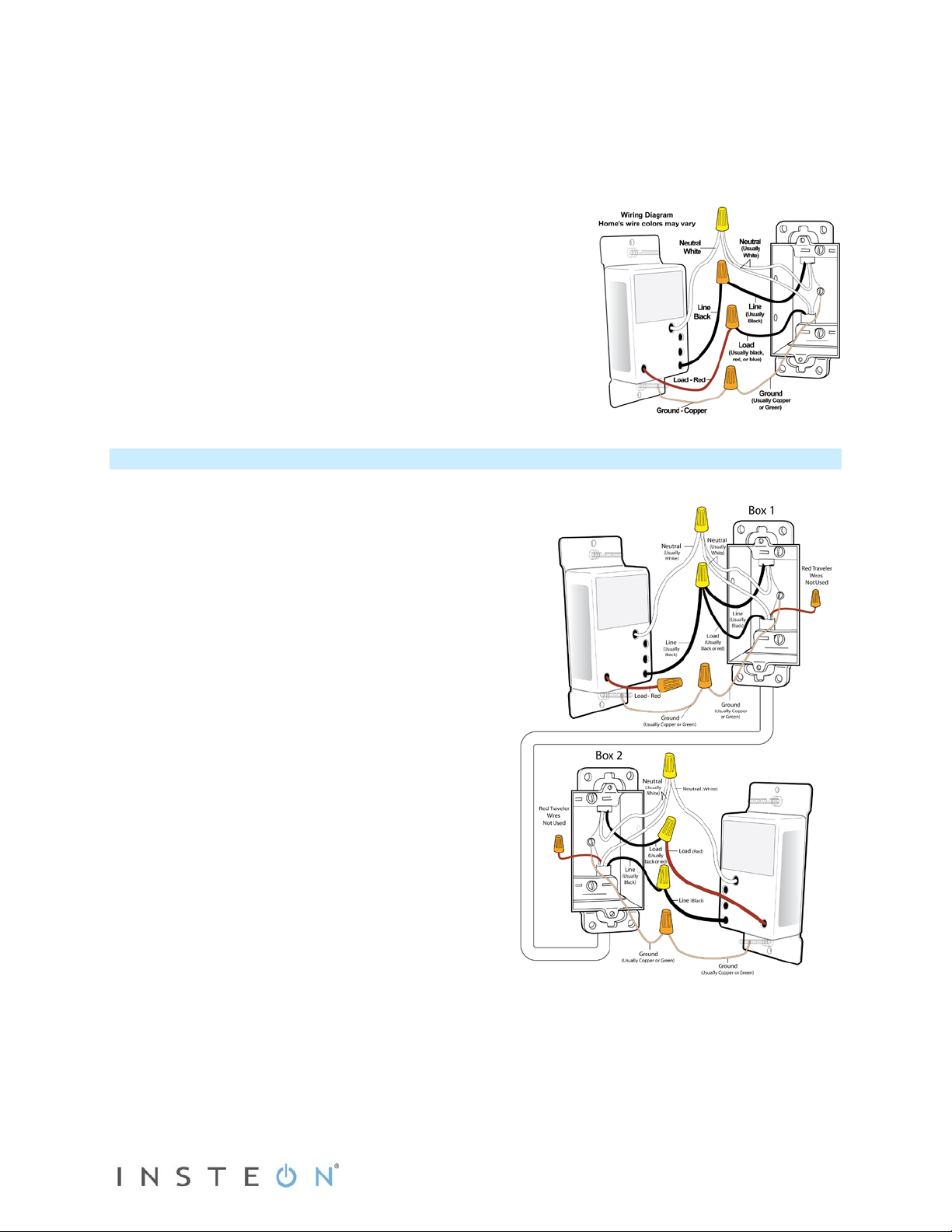
8) Connect wires as per table/diagram (confirm firm attachments with no exposed wire)
If you are installing SwitchLinc in a multi-gang box next to another switch, you may need to
remove one or both pairs of metal heatsink tabs on the back of SwitchLinc. Note that removing a
pair of tabs will derate SwitchLinc from 1000W to 800W (one pair removed) or 600W (both pairs
removed).
9) With LEDs on left, gently place SwitchLinc into wall box and screw into place
10) Turn on power
SwitchLinc and its connected load will turn on
11) Verify SwitchLinc is working properly by tapping SwitchLinc on
and off
SwitchLinc and its connected load will turn on and off
12) Reinstall the wallplate
Installation – Circuit with 2 Switches (a.k.a. 3-way circuit)
Circuits with 2 switches are called 3-way circuits. Both switches in a 3-way circuit need to be replaced by
SwitchLincs (and/or other INSTEON devices).
1) Turn off circuit breaker(s) and/or remove fuse(s)
feeding wall boxes (verify that power is off)
2) Pull both switches from their wall boxes (each
switch will have no less than 3 wires)
3) Remove wires from existing switches
4) Make sure wires are safely separated from each
other and turn power back on
5) Using a voltage meter measure each wire to
ground in both boxes until you find the single wire
supplying 120V (line)
a. We will now refer to that location as Box 1
b. The other box will have the load wire. That will
be Box 2
6) Turn power back off
In Box 1 (Line box)
7) Connect bare SwitchLinc ground to bare ground
wire or ground screw in wall box
8) Connect SwitchL in c white wire to neutral wire(s) in
wall box (usually white)
9) Using a wire nut, cap SwitchLinc red wire.
10) Connect SwitchLinc black wire to Line wir e in w al l
box (usually black) along with one traveler wire
running between boxes. (preferably b l a ck) Note
color of this traveler – it will carry 120V/line voltage
to Box 2.
11) Cap unused traveler
In Box 2 (Load box)
12) Connect SwitchLinc bare wire to bare ground wire or ground screw in wall box
Page 4 of 15 Rev: 1/21/2014 7:29 AM
13) Connect SwitchL in c white wire to neutral wire(s) i n wall box (usually white)
14) Connect SwitchLinc red wire to load wire
15) Connect SwitchLinc black wire to same color traveler from Box 1 carrying Line (usually black)
16) Cap unused traveler wire
17) With LEDs on left, gently place SwitchLincs into their wall boxes and screw in plac e
18) Turn power back on
SwitchLincs and connected load will turn on (only SwitchLinc in Box 2 will operate load)
19) Add both SwitchLincs to a group. See “Groups”
20) Verify both SwitchLincs are working properly by tapping on and off on each SwitchLinc
Both SwitchLincs and the connected load will remain in synch
21) Reinstall wallplates
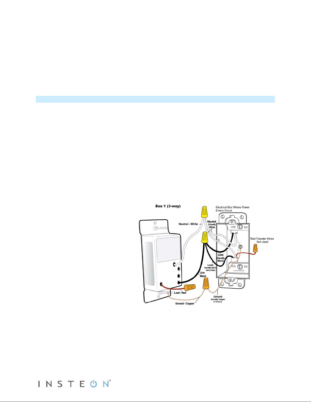
Installation – Circuit with 3 (or more) Switches
Circuits with 3 or more switches are called 4-way (or 5-way, etc.) All switches in 3-way/4-way circuits
need to be replaced by INSTEON devices.
1) Turn off circuit breaker(s) and/or remove fuse(s) feeding wall boxes (verify that power is off)
2) Pull all three switches from their wall boxes (4-way (and higher) switches have 3 or 4 wires)
3) Remove wires from existing switches
4) Make sure wires are safely separated from each other and turn power back on
5) Using a voltage meter measure each wire to ground in all three boxes until you find the single wire
supplying 120V (line)
a. We will now refer to that location as Box 1
b. The location having 2 sets of matching pairs of wires will be Box 2 (i.e. 2 reds and 2 blacks, or
other matching colors). These are 2 travelers from Box 1 and 2 travelers leading to Box 3
c. The last box will have the load wire. That will be Box 3
6) Turn power back off
In Box 1 (Line box)
7) Connect SwitchLinc bare wire to
ground
8) Connect SwitchL inc w hite wire to
neutral
9) Cap SwitchLinc red wire
10) Connect SwitchLinc black wire to line
plus one traveler (preferably black)
and note color of traveler you are
using as this will carry line voltage to
Box 2
11) Cap unused traveler wire
Page 5 of 15 Rev: 1/21/2014 7:29 AM
 Loading...