

Page 1
Quick Start Guide
p
pp
g
(on)
SwitchLincTM Relay – INSTEON® Remote Control On/Off Switch
(Non-Dimming), 3-Wire
Model: 2476S -15 Amps, Rev 5.5
Introduction
Remotely control lights and other non-dimmable devices in your home at the
touch of a button. Send commands to SwitchLinc from an INSTEON
controller. Or, conveniently control other linked INSTEON devices through the
SwitchLinc paddle.
Preparation
Installation should be performed only by a qualified electrician or a
homeowner who is familiar and comfortable with electrical circuitry. If you
have any questions regarding installation, we suggest consulting an
electrician. If you have any questions regarding setup, contact the INSTEON
Support Line.
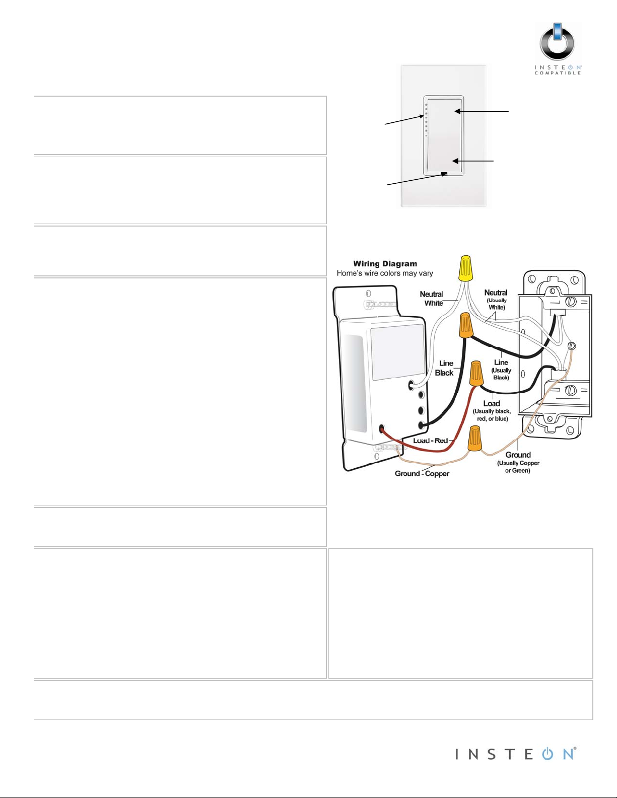
LED bar
Set button
Tools Needed
Phillips and flathead screwdriver
Wire cutter/stripper
Volta
e tester to identify wires inside the junction box
Installation (Typical 2-Way Circuit)
Note: For multi-way circuit installation, refer to the Owner’s Manual.
1) At the circuit breaker or fuse panel, disable the circuit supplying
power to the switch.
2) Remove the wallplate from the existing switch, then unscrew the
switch and pull it out from the junction box.
3) Disconnect the wires from the switch you are replacing and ensure
you have 1/2” of bare wire on the ends.
4) To correctly identify the Line, Load, Neutral and Ground wires,
enable power to the switch from the circuit breaker or fuse panel,
use a line voltage meter, then turn the breaker off again. See Figure
1 to properly connect your wires to the INSTEON device.
Note: Mechanical switches don’t utilize Neutral wires, but they are
usually available in the back of the switch box.
5) Ensure that all wire connectors are firmly attached and that there is
no exposed copper except for the Ground wire.
6) Orient SwitchLinc with the LED bar at the left, gently place it into the
junction box and screw it into place.
7) Enable power to the switch from the circuit breaker or fuse panel.
8) Test that SwitchLinc is working properly by turning the light on and
off.
9) Reinstall the wallplate.
Using SwitchLinc
Tap the paddle top to turn your light on.
Ta
the paddle bottom to turn your light off.
Using SwitchLinc as a Controller
1) Set SwitchLinc to linking mode* by pressing and holding the Set
button until it beeps (3 seconds).
2) At the responder, set it to the state you wish to activate from
3) Press and hold the responder’s Set button for 3 seconds.
4) Confirm that linking was successful by tapping the paddle on
Complete Instructions, Troubleshooting and Tech Support
Owner’s Manual: http://wiki.smarthome.com/index.php?title=2476S_Manual
Call: INSTEON Su
*Setup modes will automatically time out after 4 minutes
Page 1 of 1
Rev. 03-23-2012
The top LED should begin blinking.
SwitchLinc.
SwitchLinc should double-beep and its LED should stop
blinking.
SwitchLinc on and then off.
The responder should respond appropriately.
ort Line at 800-762-7845
Limited Warranty – INSTEON warrants to original consumer of this product for a period of 2 years from date of purchase, this product will be free from
defects in material and workm anship and will perform in substantia l conformity with its Owner's Manua l. Warranty shall not apply to def ects caused by
misuse or neglect.
Protected under U.S. and foreign patents (see www.insteon.com) © Copyright 2012
INSTEON, 16542 Millikan Ave., Irvine, CA 92606, 800-762-7845
Using SwitchLinc as a Responder
1) Set your INSTEON Controller to linking mode*. (For most
controllers, press and hold the Set button for 3 seconds or
an On/Scene button for 10 seconds.)
2) Press and hold the Set button on SwitchLinc until it doublebeeps (3 seconds).
3) Confirm that linking was successful by tapping the button
you just linked to on the controller.
Paddle top
Paddle bottom
(off)
Figure 1
The top LED should flash, and then turn on solid.
The load connected to SwitchLinc should respond
appropriately.
 Loading...