

Page 1
Quick-Start Guide
In-LineLincTM Relay - INSTEON® On/Off Module
(non-dimming) with Sense
Model: 2475S2 – 15 Amps, Rev 5.3+
Introduction
Your new INSTEON In-LineLinc On/Off Module with
Sense wires in-line for ceiling fans and fluorescent
lighting circuits without wall switches. Independent load
wires allow you to control devices of any voltage up to
120V. Or, use the Sense wire to control linked
INSTEON devices based on the state of the load
attached to In-LineLinc.
Preparation
Installation should be performed only by a qualified
electrician or a homeowner who is familiar and
comfortable with electrical circuitry. If you have any
questions regarding installation, we suggest consulting
an electrician. If you have any questions regarding
setup, contact the INSTEON Support Line.
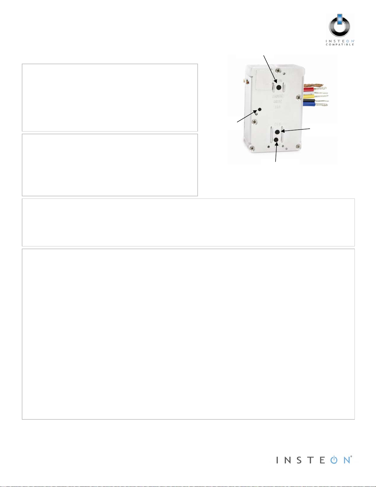
On button
Status LED
Off button
Set button
Tools Needed
Phillips screwdriver
Wire
cutter/stripper
Voltage tester to identify wires inside the junction box
Probe that is non-conductive to press the Set button (e.g., pencil)
Installation
1) If you plan to configure In-LineLinc using INSTEON-compatible software, write down the INSTEON I.D.
and the location of the fixture you’ll be controlling (e.g., 01.F7.G5, Mike’s bedroom light).
2) At the circuit breaker or fuse panel, disable the circuit supplying power to the fixture.
3) Remove the wallplate from the fixture you are replacing. Unscrew the fixture itself and pull it out from the
junction box.
4) Disconnect the wires from the fixture you will be controlling and ensure that you have ½” of bare wire on
the ends.
5) To correctly identify the Line, Load, Neutral and Ground wires, enable power to the fixture from the
circuit breaker or fuse panel, use a line voltage meter, and then turn the breaker off again.
6) Wiring – Reference either the diagram for “Typical Wiring (without Sense)” or “Wiring with Sense” on the
next page to properly connect In-LineLinc to the fixture.
7) Prior to reinstalling the fixture, enable power to the fixture from the circuit breaker or fuse panel.
8) Use the On/Off buttons to test that the module is working and controlling the load.
9) Follow the linking instructions on the next page to link your device to In-LineLinc.
a. Typical wiring (without Sense) – “Linking In-LineLinc as an INSTEON Responder”
b. Wiring with Sense – “Linking In-LineLinc as an INSTEON Controller”
10) Gently place In-LineLinc into the junction box, making sure that nothing could accidentally press any of
the buttons on its face.
11) Reinstall the fixture.
Page 1
Rev. 03-
of 2
15-2012
Limited Warranty – INSTEON warrants to original consumer of this product for a period of 2 years from date of purchase,
this product will be free from defects in material and workmanship and will perform in substantial conformity with its Owner's
Manual. Warranty shall not apply to defects caused by misuse or neglect.
Protected under U.S. and foreign patents (see www.insteon.com) © Copyright 2012
INSTEON, 16542 Millikan Ave., Irvine, CA 92606, 800-762-7845
Page 2
(
Quick Start Guide INSTEON In-LineLinc On/Off Module with Sense
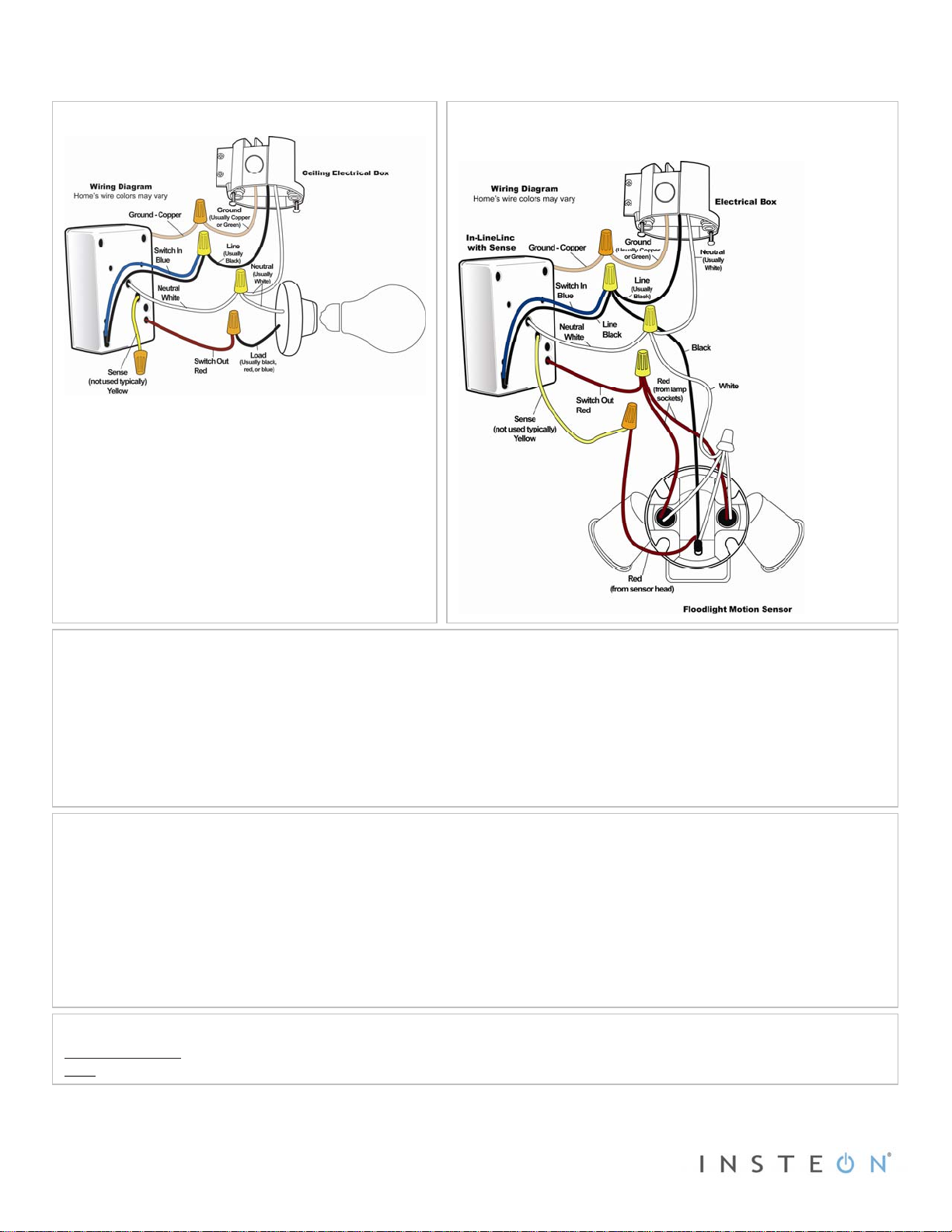
Typical Wiring (without Sense)
Motion Sensor Floodlight shown as an example
Wiring with Sense
NOTE: If you do not plan on using the Sense wire, be
sure to deactivate it before completing installation.
To deactivate the Sense wire:
1) Press and hold the Set button until it beeps (3
seconds).
The In-LineLinc Status LED should begin
blinking.
2) Double-tap the Set button.
In-LineLinc should beep and its Status LED
should stop blinking and turn on solid if the
load is off or turn off if the load is on.
Linking In-LineLinc as an INSTEON Responder
1) Set your INSTEON controller to linking mode.* (For most controllers, press and hold the Set button for 3
seconds or an On/Scene button for 10 seconds.)
2) Press and hold the Set button on In-LineLinc until it double-beeps (3 seconds).
The In-LineLinc Status LED should flash once and then turn on solid if the load is off or turn off if the
load is on.
3) Confirm that linking was successful by tapping the button you just linked to on the controller.
The load connected to In-LineLinc should respond appropriately.
Linking In-LineLinc as an INSTEON Controller
Note: The following instructions will allow you to use the In-LineLinc Sense wire to activate other INSTEON devices.
1) Set In-LineLinc to linking mode* by pressing and holding the Set button until it beeps (3 seconds).
The In-LineLinc Status LED will begin blinking.
2) Set the responder to the state you wish to activate from In-LineLinc.
3) Press and hold the responder’s Set button for 3 seconds.
In-LineLinc should double-beep and its LED should stop blinking and turn on solid.
4) Confirm that linking was successful by tapping the On/Off buttons on In-LineLinc.
The responder should respond appropriately.
Complete Instructions, Troubleshooting and Tech Support
Owner’s Manual: http://wiki.smarthome.com/index.php?title=2475S2_Manual
INSTEON Support Line at 800-762-7845
Call:
*Setup modes will automatically time out after 4 minutes.
SmartLabs Limited Warranty – SmartLabs warr ants to original consum er of this product for a period of 2 years from date of purch ase, this product will be
free from defects in material & workmanship & will pe rform in subs tantial conform ity with its Owner' s Manual. W arranty shall not appl y to defects caus ed by
Page 2 of 2
Rev. 03-15-2012
misuse or neglect.
Protected under U.S. and foreign patents (see www.insteon.com) © Copyright 2012
SmartLabs, 16542 Millikan Ave., Irvine, CA 92606, 1-800-SMARTHOME
800-762-7846)
 Loading...