

Page 1
no exposed wire, turn on breaker/fuse
Quick Start Guide
Pin 4
(Left side)
Group 1: triggers when switch between pin 3 & 4 is closed
Group 2: triggers when switch between
Group 3: triggers when switch between
Group 4: triggers when switch between pin 2 & 4 is opened
Line (Black)
Set button
Status LED
Load 2 (Red)
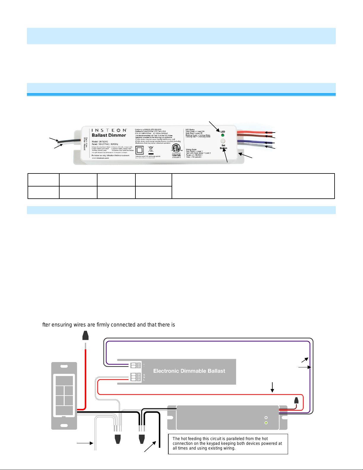
The hot feeding this circuit is paralleled from the hot
RJ-10 jack
0-10VDC + (Purple)
Neutral (White)
Line (Black)
Ballast Dimmer
INSTEON® Remote Control 0-10VDC Ballast Dimmer or Dual Switch
Model: 2475DA2 (US), 2446-422 (EU), 2446-522 (AUS/NZ)
About Ballast Dimmer
This in-line ballast control module supports two different operational modes: dimmer and dual-relay. For use in new construction
or retrofit (inside or outside the fixture) where saving energy is a priority.
Neutral (White)
RJ-10 Mini-modular jack pin-outs:
Ground Group 1 - 2 Group 3-4 12-15VDC
Install Ballast Dimmer for Dimmable Ballast
Pin 3 Pin 2 Pin 1
Load 1 (Red/Black)
0-10VDC + (Purple)
DC ground (Grey)
pin 3 & 4 is opened
pin 2 & 4 is closed
Note: use with branch circuit breakers 15 Amperes or fewer.
1) Write down the INSTEON ID found on the front of the unit
(XX.XX.XX)
2) Turn off breaker/fuse and verify that the power is off
3) Disconnect wires from existing switch
4) Connect wires per diagram
5) At the ballast location, disconnect the wires from the fixture
you will be controlling and ensure that you have ½ inch of
bare wire on the ends
6) See the diagram to identify and connect the line, load,
neutral DC(+) and DC(-) w ires on Ballast Dimmer. Be sure
you have correctly identified the wires in the jun ctio n box
before connecting them.
7) After ensuring wires are firmly connected and that there is
2475DA2 Rev. 7/24/2013 8:55 AM / See Owner’s Manual for Warranty Information.
Protected under U.S. and foreign patents (see www.insteon.com/patents)
© Copyright 2013 INSTEON, 16542 Millikan Ave., Irvine, CA 92606, 866-243-8022
After a few seconds, load will turn on
8) Test Ballast Dimmer connection by tapping set button a
couple times
Ballast Dimmer load will respond appropriately
9) Link Ballast Dimmer to your INSTEON keypad or other
INSTEON controller. See Make Ballast Dimmer a
Responder.
10) Gently place Ballast Dimmer into the fixture box, making
sure nothing could accidentally press on the set button
11) Reinstall the fixture
DC ground (Grey)
Load 2 (Red)
connection on the keypad keeping both devices powered at
all times and using existing wi rin g.
Page 2
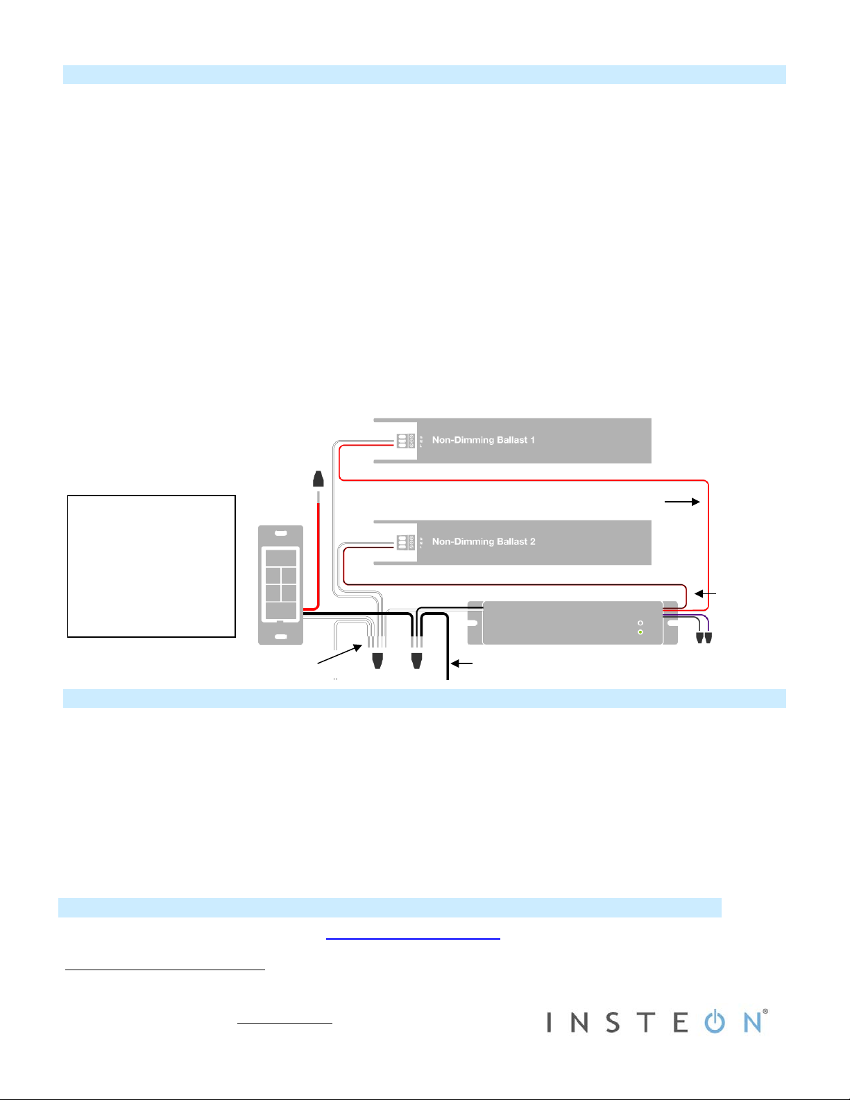
Install Ballast Dimmer for Dual Relay
Diagram showing only the
Owner’s Manual and Tech Support
Load 1 (Red)
Load 2 (Red/Black)
Line (Black)
Neutral (White)
1) Write down the INTEON ID found on the front of the unit (XX.XX.XX)
2) Turn off breaker/fuse and verify that the power is off
3) Disconnect wires from existing switch
4) Connect the wires per diagram
5) At the ballast location, disconnect the wires from the fixture you will be controlling and ensure that you have ½ inch of bare
wire on the ends
6) See the diagram to identify and connect the line, load 1, load 2 and neutral wires on Ballast Dimmer. Be sure you have
correctly identified the wires in the junction box before connecting them.
7) Place wire nuts on the unused gray and purple wires
8) After ensuring wires are firmly connected and that there is no exposed wire, turn on breaker/fuse
After a few seconds, load will turn on
9) Change to dual relay mode:
a. Press and hold set button until it beeps
LED will start blinking green
b. Tap set button twice
Ballast Dimmer will beep once and LED will stop blinking
10) Test the Ballast Dimmer connection by tapping set button a couple times
11) Link Ballast Dimmer to your INSTEON keypad or other INSTEON controller. See Make Ballast Dimmer a Responder.
12) Gently place Ballast Dimmer into the fixture box, making sure nothing could accid entally press the set button
13) Reinstall the fixture
non-dimming connection to
ballast 1 and 2.
The hot feeding this circuit is
paralleled from the hot
connection on the keypad
keeping both devices
powered at all times and
using existing wiring.
Make Ballast Dimmer a Responder
1) Use Ballast Dimmer set button to set the load to the state you wish to activate from the controller (turn it on if you wish it to be
on when the controller activates the scene, etc.)
2) Press and hold the scene controller button until it beeps
3) Press and hold Ballast Dimmer set button until it double-beeps
Controller will double-beep2and its LED will stop blinking
4) Test by tapping controller button on and off
Load connected to Ballast Dimmer will respond appropriately
Owner’s Manual and current Quick Start Guide: http://www.insteon.com/support
Call: INSTEON Support Line at 866-243-8022
1
If the controller does not have a beeper, wait until its LED begins blinking
2
Most models
2475DA2 Rev. 7/24/2013 8:55 AM / See Owner’s Manual for Warranty Information.
Protected under U.S. and foreign patents (see www.insteon.com/patents)
© Copyright 2013 INSTEON, 16542 Millikan Ave., Irvine, CA 92606, 866-243-8022
1
 Loading...