

Page 1
SwitchLinc™ 2-Wire Dimmer (RF)
INSTEON® Remote Control Switch
Owner’s Manual
#2474DWH
Page 1 of 15 2474DWH- Rev: 1/21/2014 7:30 AM
Page 2

About SwitchLinc 2-Wire Dimmer (RF) ..................................................................................................... 3
Features and Benefits ................................................................................................................................. 3
Identifying the Electrical Wires in Your Home ........................................................................................... 4
Installation ................................................................................................................................................... 4
Local Control ............................................................................................................................................... 6
INSTEON Setup ........................................................................................................................................... 6
INSTEON Controllers, Responders and Links .......................................................................................... 6
Make SwitchLinc an INSTEON Responder ............................................................................................... 7
Make SwitchLinc an INSTEON Controller ................................................................................................. 7
Synchronizing Devices in Groups ............................................................................................................. 7
Scenes ....................................................................................................................................................... 8
Make SwitchLinc a Controller of Multiple INSTEON Responders ............................................................. 8
Remove SwitchLinc as an INSTEON Controller ....................................................................................... 8
Remove SwitchLinc as an INSTEON Responder ..................................................................................... 9
Remove SwitchLinc as a Controller of Multiple INSTEON Responders ................................................... 9
Factory Reset ............................................................................................................................................ 9
Adjust Local Settings (optional) .............................................................................................................. 10
Local On-Level ........................................................................................................................................ 10
Local Ramp Rate ..................................................................................................................................... 10
Resume Dim ............................................................................................................................................ 11
Change LED Brightness .......................................................................................................................... 11
Error Blink ................................................................................................................................................ 11
Specifications ............................................................................................................................................ 12
Troubleshooting ........................................................................................................................................ 14
Certification and Warranty ....................................................................................................................... 15
Certification .............................................................................................................................................. 15
FCC and Industry Canada Compliance Statement ................................................................................. 15
ETL / UL Warning (Safety Warning) ........................................................................................................ 15
Limited Warranty ..................................................................................................................................... 15
Page 2 of 15 2474DWH- Rev: 1/21/2014 7:30 AM
Page 3
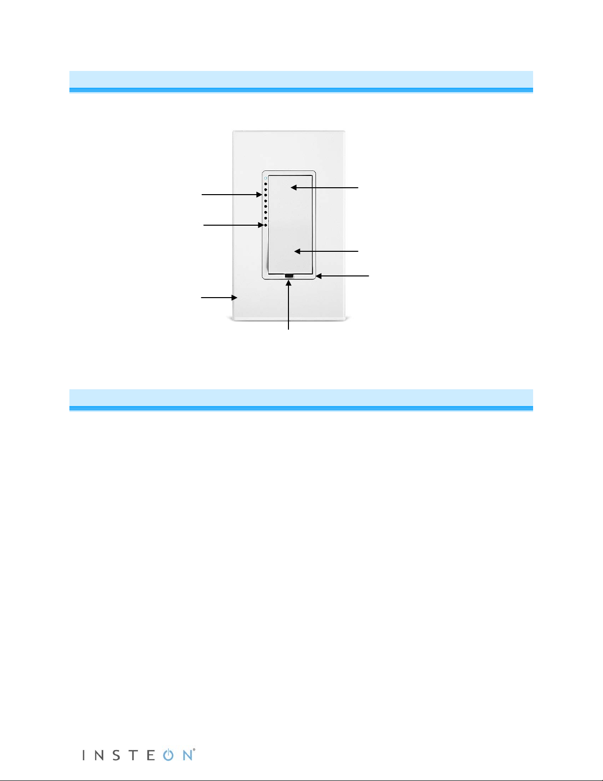
About SwitchLinc 2-Wire Dimmer (RF)
Paddle top
Paddle bottom
Set button (push)
LED bar
indicator
Trim frame
Wallplate
OFF indicator
brightness
and programming
mode LED
(sold separately)
Air gap (pull)
(ON/brighten)
(OFF/dim)
Features and Benefits
• No Neutral wire required
• Simple 2-wire connection replaces any wall switch
• Controls incandescent lamps between 25W and 600W
• Beeper and dual-color LED for easy setup
• 32 brightness levels from 3% to 100%
• 32 ramp rates from 0.1 second to 9 seconds (manual setup) or up to 8 minutes (software setup)
• 9-level LED bar shows brightness of lights
• Status LED acts as a gentle nightlight w hen switch is of f
• Non-volatile memory retains all settings through power outages
• Optional kit swaps out white LED pipes with green, blue, amber or red LEDs
• Optional kit swaps out white paddle and trim frame with ivory, almond, black, brown or gray
• Two-year warranty
Page 3 of 15 2474DWH- Rev: 1/21/2014 7:30 AM
Page 4
CAUTIONS AND WARNINGS
with electrical circuitry, have a qualified electrician install the product for you.
In the Box
Tools Needed
Optional Accessories
SwitchLinc 2-Wire Dimmer (RF)
Flathead screwdriver
Mini Remote / RemoteLinc 2
Three (3) wire nuts
Phillips screwdriver
SmartLinc Central Controller
Two (2) screws
Wire cutter/stripper
Quick Start Guide
Voltage meter
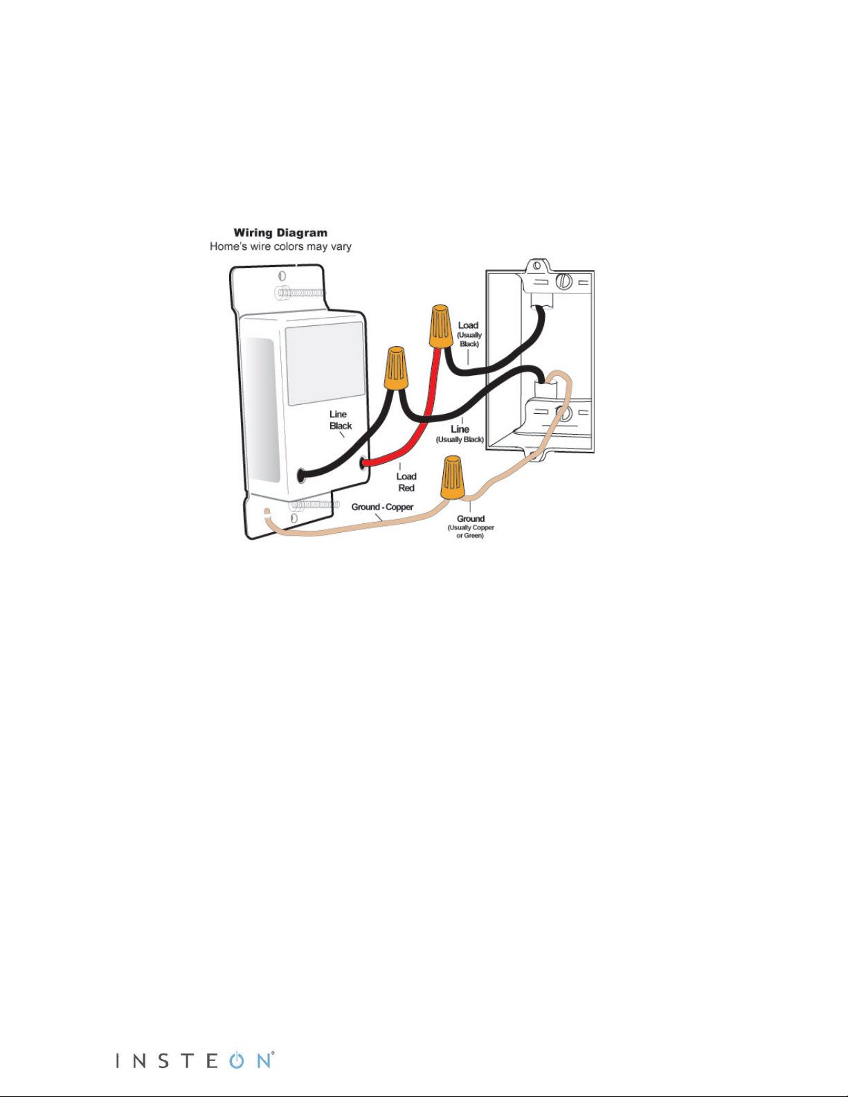
SwitchLinc Wire
Wire in Wall (common colors)
Bare copper
Ground (bare copper, green wire or green screw)
Red
Light/load (red or blue)
Black
Line (black)
- Read and understand these instructions before installing and retain them for future reference.
- This product is intended for installation in accordance with the National Electric Code and local regulations in the United
States or the Canadian Electrical Code and local regulations in Canada. Use indoors only. This product is not designed or
approved for use on power lines other than 120V 60Hz, single phase. Attempting to use this product on non-approved
power lines may have hazardous consequences.
Recommended installation practices:
- Use only indoors or in an outdoor rated box.
- Be sure that you have turned off the circuit breaker or removed the fuse for the circuit into which you are installing this
product. Installing this product with the power on will expose you to dangerous voltages.
- Connect using only copper or copper-clad wire.
- This product may feel warm during operation. The amount of heat generated is within approved limits and poses no
hazards. To minimize heat buildup, ensure the area surrounding the rear of this product is as clear of clutter as possible.
- Each INSTEON product is assigned a unique INSTEON ID, which is printed on the product’s label.
- To reduce the risk of overheating and possible damage to other equipment, do not use this product to control loads in
excess of the specified maximum(s) or, install in locations with electricity specifications which are outside of the product’s
specifications. If this device supports dimming, please note that dimming an inductive load, such as a fan or transformer,
could cause damage to the dimmer, the load bearing device, or both. If the manufacturer of the load device does not
recommend dimming, use a non-dimming INSTEON on/off switch. USER ASSUMES ALL RISKS ASSOCIATED WITH
DIMMING AN INDUCTIVE LOAD.
Identifying the Electrical Wires in Your Home
- Line – carries 120VAC/60Hz electricity into the box (may also be called Hot, Live or Power), commonly black
- Load – usually black from a separate cable jacket
- Ground – Bare wire or metal fixture (if grounded)
IMPORTANT! If you have any difficulties or questions, consult an electrician. If you are not knowledgeable about or comfortable
Installation
1) At electrical panel, turn off circuit breaker(s) feeding wall box (verify that power is off).
2) Remove wallplate, unscrew the switch you are replacing and gently pull out.
3) Disconnect wires from switch.
4) After making sure the wires are not touching, turn breaker back on.
5) Use a voltage meter to identify the line, load and ground wires.
6) Turn breaker back off.
7) Connect wires as follo ws u s ing included wire nuts:
1
8) Gently place SwitchLinc into wall box, orient the LED bar on left and screw into place.
1
If the wires cannot be detached by unscrewing them, cut the wires where they enter the switch, then strip ½” of insulation off the ends.
Page 4 of 15 2474DWH- Rev: 1/21/2014 7:30 AM
Page 5
9) Turn breaker on.
Light will turn on.
LED will indicate load brightness.
10) Verify SwitchLinc is working properly by toggling the light on and off.
11) Reinstall the wallplate.
Page 5 of 15 2474DWH- Rev: 1/21/2014 7:30 AM
Page 6

Connected Light and Responders
Paddle
Tap
Press and hold
Double-tap
LED
position)
Controller
Responder
Link
Tap for ON, Press and hold to brighten
Tap for OFF, Press and hold to dim
Local Control
Follow these instructions to control the light/load (as well as any responders) from the dimmer paddle.
Top
Bottom
On
(ramped)
Off
(ramped)
Brighten
(until release or 100%)
Dim
(until release or off)
On
(instant)
Off
(instant)
White
White
(in
bottom
INSTEON Setup
Some products have subtle differences in their setup procedures. Please refer to the other device’s
owner’s manual for details.
INSTEON Controllers, Responders and Links
Let’s define a few terms.
• The INSTEON “transmitter” is called a controller.
• The INSTEON “receiver” is called a responder.
• The association between the controller and responder is called a link.
Page 6 of 15 2474DWH- Rev: 1/21/2014 7:30 AM
Page 7

Note that a link is one way. If you wish to have two-way control, simply add a link from the responder to
the controller.
Make SwitchLinc an INSTEON Responder
Follow the steps below to create a link, enabling another INSTEON device to control SwitchLinc.
1) Press and hold controller button until beep.
Controller LED will start blinking green.
2) Adjust SwitchLinc to desired brightness for link.
Load will turn on and LED will turn white.
3) Press and hold SwitchLinc Set butt on until double-beep.
Controller will double-beep and LED will stop blinking.
4) Test by tapping controller button on and off.
SwitchLinc will turn on and off.
Notes:
- The link just created is one way. See Make SwitchLinc an INSTEON Controller
to add another link to
keep the two products in synch.
- If you wish the load to be off when link is activated (such as for an “all off” scene), turn the load off in
step 2.
Make SwitchLinc an INSTEON Controller
Follow the steps below to create a link, enabling SwitchLinc to control another INSTEON device.
1) Press and hold SwitchLinc Set button until beep.
LED will start blinking green.
2) Adjust responder to desired brightness/state.
3) Press and hold responder Set button until double-beep.
SwitchLinc LED will stop blinking.
SwitchLinc will double-beep.
2
3
1
4) Test by tapping SwitchLinc paddle on and off.
Responder will turn on and off.
Notes:
- To add multiple responders, repeat steps 1-5.
- The link just created is one way. See Make SwitchLinc an INSTEON Responder
to add another link
to keep the two products in synch.
Synchronizing Devices in Groups
Devices in a group share all the same settings (e.g., on-level, ramp rate). This keeps all group members
synchronized. Every device in a group is both a controller of and a responder to all the other devic es . The
most common example of a group is a 3-way lighting c ir c uit (2 switches controlling the same load).
The following steps will create a virtual 3-way circuit including de vice A a nd de vic e B. For simplicity, we
will assume that the desired group level is “all on.”
1) Turn both A and B on.
2) Press and hold A’s Set button until beep.
A status LED will start blinking green.
3) Press and hold B’s Set button until double-beep.
A will double-beep and its LED will stop blinking. A is now a controller of B.
1
If the responder is a multi-scene device such as a KeypadLinc, tap the scene button you wish to control until its LED is in the desired scene state (on or off). You can program
any state, not just on, for the responder’s link.
2
If either the SwitchLinc or responder’s LED continues to blink, the addition failed. Tap the device’s Set button until LED stops blinking and try again.
3
If either the SwitchLinc or responder’s LED continues to blink, the addition failed. Tap the device’s Set button until LED stops blinking and try again.
Page 7 of 15 2474DWH- Rev: 1/21/2014 7:30 AM
Page 8

4) Press and hold B’s Set button until beep.
B LED will start blinking green.
5) Press and hold A’s Set button until double-beep.
B will double-beep and its LED will stop blinking. B is now a controller of A.
6) Test by turning load on and off from A and then B.
The load(s) and both A and B LEDs will be in synch.
Scenes
In a scene, each device can be activated at different individual settings. Scenes allow you to create
environments with advanced lighting, audio, etc. Software (such as HouseLinc) is recommended for
scene management.
Here’s an example of how to set up a scene with one controller and SwitchLinc as a member:
1) Press and hold controller button until beep.
Controller LED will start blinking green.
2) Tap controller Set button.
Controller LED starts double-blinking green.
3) Tap SwitchLinc on and adjust to desired scene brightness.
SwitchLinc LED will be green.
4) Press and hold SwitchLinc Set butt on until double-beep.
5) For each additional scene member:
a. Adjust member to desired scene brightness.
b. Press and hold Set button until double-beep.
6) Tap controller Set button
Controller will beep and LED stops blinking.
7) Test by tapping controller button on and off
SwitchLinc and other scene responders will all respond appropriately.
Make SwitchLinc a Controller of Multiple INSTEON Responders
1) Press and hold SwitchLinc Set button until beep.
LED starts blinking green.
2) Tap SwitchLinc Set button.
LED starts double-blinking green.
3) For each additional responder:
a. Adjust responder to desired scene brightness/state.
b. Press and hold Set butt on unti l doub le-beep.
4) Tap SwitchLinc Set button.
SwitchLinc will beep and LED will stop blinking.
5) Test by tapping the SwitchLinc on and off.
All the responders will turn on and off.
Remove SwitchLinc as an INSTEON Controller
If you no longer want SwitchLinc to control another device (or are removing SwitchLinc) it is important that
you follow the instructions below for each responder.
1) Press and hold SwitchLinc Set butt on until beep.
LED will start blinking green.
2) Press and hold SwitchLinc Set button until beep.
LED will start blinking red.
3) Press and hold responder Set butt on until double-beep.
Page 8 of 15 2474DWH- Rev: 1/21/2014 7:30 AM
Page 9

SwitchLinc will double-beep and LED stops blinking.
4) Test by tapping SwitchLinc on and off.
Former responder will not respond.
Remove SwitchLinc as an INSTEON Responder
If you no longer want a controller or specific controller button to control SwitchLinc, follow these
directions.
Note: If you ever wish to uninstall SwitchLinc, it is important that you remove all SwitchLinc responder
links from all controllers. Otherwise, controllers will retry commands repetitively, creating network delays.
1) Press and hold controller button until beep.
LED will start blinking green.
2) Press and hold controller button until beep.
LED will start blinking red.
3) Press and hold SwitchLinc Set butt on until double-beep.
Controller LED will stop blinking.
4) Test by tapping controller button on and off.
SwitchLinc will no longer res pond.
Remove SwitchLinc as a Controller of Multiple INSTEON Responders
1) Press and hold SwitchLinc Set button until beep.
LED will start blinking green.
2) Press and hold SwitchLinc Set button until beep.
LED will start blinking red.
3) Tap SwitchLinc Set button
LED will start double-blinking red.
4) For each responder you are removing, press and hold Set button until double-beep.
5) Tap SwitchLinc Set button.
SwitchLinc will beep and LED will stop blinking.
6) Test by tapping the SwitchLinc on and off.
None of the former responders will respond.
Factory Reset
Resetting SwitchLinc will er as e all settings and scenes.
1) Pull out Set button to create an air gap (this removes power to SwitchLinc).
2) Press and hold in Set butto n. Do not let go.
SwitchLinc will begin to emit a long beep.
3) When beep stops, release Set button.
After a few seconds SwitchLinc will double-beep.
SwitchLinc will turn on and LED will turn white.
Page 9 of 15 2474DWH- Rev: 1/21/2014 7:30 AM
Page 10

Adjust Local Settings (optional)
Local On-Level
The local on-level is the brightness that the SwitchLinc will come on when turned on at the SwitchLinc
paddle, with the default level at 100%. Local on-level can be set to any one of 32 fixed brightness levels
(3% to 100%) or “resume bright” (brightness prior to last being turned off).
1) Adjust light to desired brightness (or off for resume dim).
2) Tap the Set button.
SwitchLinc will beep.
3) Test by tapping SwitchLinc on and off.
The light should come on at the programmed on-level (or previous level prior to turning off for
resume dim).
Local Ramp Rate
The local ramp rate is the time it takes for SwitchLinc to reach 100% brightness (from off) when controlled
at the paddle. The default ramp rate is 0.5 seconds, but it is adjustable from instant-on to 9 seconds
(using Set button) or up to 8 minutes (with software).
The ramp rate is set up using the light’s brightness level as the indicator for the ramping speed: the
brighter the light, the faster the ramp rate. Refer to this table to help you set your desired ramp rate:
Brightness Level Ramp Rate in Seconds
90-100% 0.1
77-86% 0.2
65-74% 0.3
52-61% 2.0
39-48% 2.0
26-35% 4.5
13-23% 6.5
1-10% 8.5
1% 9.0
1) Adjust the connected light(s) to the brightness corresponding with your desired ramp rate (see table
above).
2) Quickly double-tap SwitchL inc’s Set button.
SwitchLinc will beep.
3) Test ramp rate settings but tapping SwitchLinc or controller button on and off.
The connected light(s) will turn on and off at the programmed ramp rate(s).
4) If the ramp rate is not as desired:
Page 10 of 15 2474DWH- Rev: 1/21/2014 7:30 AM
Page 11

a. Go back to step 1 and repeat the process.
b. Your Set button double-tap in step 2 might not have been fast enough, and you may have
accidentually reprogrammed the local on-level instead.
Note: HouseLinc (and other home automation software) will allow you to set on-levels and ramp rates to
your exact specifications—it even extends the maximum ramp rate from 9 seconds to 8 minutes—and
apply them consistently to m ultiple devices thr oug hou t your hom e.
Resume Dim
When resume dim is enabled, each time you turn on the SwitchLinc it will turn on at the previous dim level
prior to turning off. The default resume dim level is full-on, but to change the desired level, simply dim or
brighten to the new desired level and turn the SwitchLinc off. The next time you turn on SwitchLinc, it will
return to the last used dim level.
1) Press and hold Set button until beep.
LED starts blinking green.
2) Press and hold Set button until beep.
LED starts blinking red.
3) Press and hold Set button until beep.
LED starts blinking green.
4) Press and hold Set button until beep.
LED starts blinking red.
5) Slowly tap Set button 3 times.
LED starts double-blinking red.
6) Press and hold Set button until double-beep.
LED stops blinking.
7) Test by turning off and then back on via the local switch.
Light will ramp off and back on to resume dim level.
Change LED Brightness
SwitchLinc’s status LEDs are set to shine at a 50% brightness level, but can be adjusted from off to
100%.
1) Press and hold Set button until beep
LED starts blinking green.
2) Press and hold Set button until beep
LED starts blinking red.
3) Press and hold Set button until beep
LED starts blinking green.
4) Tap Set button once
LED starts double blinking green.
5) Press and hold Set button until beep
LED will turn white (at brightness of connected load).
6) Use the SwitchLinc’s on and/or off buttons to brighten or dim LED to desired brightness.
7) Tap Set button until double-beep.
SwitchLinc will double beep and return to ready mode.
Error Blink
SwitchLinc LED blink s red for a few seconds if one or more responder s do not ack nowledge a mes sage.
Error blink is enabled by default, but this setting is adjustable via software or a central controller only.
Page 11 of 15 2474DWH- Rev: 1/21/2014 7:30 AM
Page 12

General
SwitchLinc 2-Wire Dimmer (RF) - INSTEON Remote Control
Brand / manufacturer
INSTEON
Manufacturer product number
2474DWH
UPC
813922010817
Warranty
2 years, limited
INSTEON
INSTEON powerline mesh repeater
No
INSTEON RF mesh repeater
Yes
INSTEON controller
Yes
INSTEON responder
Yes
Maximum links / scenes
400
Load brightness levels
32 locally (256 with software)
White when load is on, bottom white LED is on when load is off
LED brightness
Adjustable, from off to bright
Local on-level
Adjustable, 32 fixed brightness levels or resume dim
Adjustable from 0.1 seconds to 9 seconds locally
Local control
Yes
On
Off
Fast-on
Fast-off
Begin bright
Begin dim
End bright
End dim
On
Off
Fast-on
Fast-off
Begin bright
Begin dim
End bright
End dim
Incremental bright
Incremental dim
Beep
Software configurable
Yes
RF range
Up to 100-feet open air
Phase bridge detect beac o n
No, INSTEON RF only device
INSTEON device category
Specifications
Product name
LED
Dimmer
Blinks red when responder does not acknowledge (can be
disabled via software).
Blinks red or green during setup.
Local ramp-rate
Commands supported as controller
Commands supported as responder
(0.1 seconds to 8 minutes via software)
0x01 dimmable lighting control (all frequencies)
Page 12 of 15 2474DWH- Rev: 1/21/2014 7:30 AM
Page 13

INSTEON device subcategory
X10
No X10 Support: INSTEON RF-only product
Mechanical
Mounting
Black – line (16 gauge)
Red – load (16 gauge)
Copper – ground (16 gauge)
Color
White paddle (color change kits available), clear back case
Set button
1, clear
Air Gap
Yes (Set button pulled out )
Plastic
UV stabilized polycarbonate
Beeper
Yes
Beep on button press
Optional (off by default)
LEDs
9 white brightness LEDs, 1 green/red status LED
Dimensions
4.1" H x 1.8" W x 1.2" D
Weight
3.6oz
Operating environment
Indoors
Operating temperature range
Operating humidity range
0-90% relative humidity
Storage temperature range
Electrical
Voltage
120VAC ±10%, split single phase
Frequency
60Hz
Load type(s)
Wired-in incandescent lighting
Maximum load
600 watts
Minimum load
25 watts
User replaceable fuse
No
Hardwired remote control
No
Retains all settings without power
Yes, saved in non-volatile EEPROM
Standby power consumption
< 1 watt
Certifications
FCC, IC Canada
FCC ID
SBP2474DWH
Safety approval(s)
ETL (Intertek Testing Services)
Wires
0x24
Single gang electrical box
32o to 104 o F (0 o to 40 o C)
-4 o to 158 o F (-20 o to 70 o C)
Page 13 of 15 2474DWH- Rev: 1/21/2014 7:30 AM
Page 14

Problem
Possible Cause
Solution
Make sure circ uit breaker is on.
The controller m ay have dropped out of
another device.
Make sure phases are detected, add additi onal
INSTEON devices .
You'll need to add an INS TEON Access Point or
powerline-only an d RF-only devices.
Remove any unused r esponders from the scene via
scene memberships.
faster ramp rate. See Local Ramp Rate.
The load doesn’t appear to
turn on right away.
Remove power to SwitchLinc by pulling out the Set
factory reset.
The SwitchLinc is not getting enough
wattage for powering its circuits .
Change the light bulb to a standard incandescent
of a small-watt age bulb.
Troubleshooting
LED won’t come on. SwitchLinc is not getting power.
Check the junction box wires to ensure all
connections are tight and no bare wires are
exposed.
Check that a standard incandescent bulb rated for
25W or more is installed.
SwitchLinc won’t add to
scene as a responder.
The controller turns
SwitchLinc off but not on.
SwitchLinc is taking a long
time to respond to a
controller.
The load turned on by
itself.
Add to a Scene mode, or added
The INSTEON signal m ay not be
reaching the “vicinity” of SwitchLinc.
Controller is a powerline-only device.
(SwitchLinc 2-Wire is RF only.)
Ramp rate may be extremely slow
SwitchLinc may be added to the scene
in the Off state.
The controller may be sending
commands to a different responder that
is no longer in use. Commands for the
unused responder ar e being resent and
slowing down communication signals to
SwitchLinc.
Ramp rate may be extrem ely slow.
Another controller or a timer could have
triggered SwitchLinc.
Try re-adding SwitchLinc to the controller again.
INSTEON devices and/or move around exis ting
dual-band device to al low communication between
Re-add SwitchLinc to controller with a faster ramp
rate. See Local Ramp Rate
Turn on the light and re-add SwitchLinc to the
controller scene.
the controller.
HINT: If you are using home automation software,
you can easily check and eliminate unnec essary
If the above doesn’t w ork, perform a fac tory reset
on the controller
Remove and re-add SwitchLinc to controller with a
Monitor for recurrence and remove device from the
SwitchLinc’s scene if you can determ ine the cause.
If necessary, per form a factory reset.
.
The ramp rate may be set too slow. Set a faster ramp rate. See Local Ramp Rate.
SwitchLinc is locked up.
The lights flicker when on
and SwitchLinc repeatedly
turns the load off and on.
If you have tried t hese solutions, revi ew ed this Owner’s Manual, and still cannot resolve an issue you are having with
SwitchLinc, please call the INSTEO N Support Line at 800-762-7845.
Page 14 of 15 2474DWH- Rev: 1/21/2014 7:30 AM
A surge on the powerline may have
caused a glitch.
power from the light bulb. The
SwitchLinc “steals” some of the bulb’ s
button to create an air gap for 10 seconds, then
pushing it back in. If that doesn’t work, perform a
bulb of at least 25W. You can always set the
brightness to a l ow er level and still have the effect
Page 15

Certification and Warranty
Certification
This product has been thoroug hly tested by Intertek - ETL SE MKO, a nationally recognized indepen dent third-party testing labo ratory. The North
American ETL Listed m ark signifies th at the device has been test ed to and has met the requi rements of a wid ely recognized co nsensus of U.S. and
Canadian device safet y standards, that the manufacturing sit e has been audited, and that the manufa cturer has agreed to a program of quar terly
factory follow-up inspections to ver ify continued conformance.
FCC and Industry Canada Compliance Statement
This device compl ies with part 15 of the FCC Rules a nd Industry Canada license-exempt RSS -210. Operation is subject to the foll owing two
conditions:
(1) This device may not cause harmful interference, and
(2) This device must accept any interference, including interference that may cause undesired operation of the device.
Le present appareil e st c o nf orm e a u x CNR d' Ind us tri e C a na da appli c ables aux appareil s r adi o exempts de licenc e. L'exploi tation est autorise a u x d eu x
conditions suivantes:
(1) l'appareil ne doit pas produire de brouillage, et
(2) l'utilisateur de l'appareil doit accepter tout brouillage radiolectrique subi, mme si le brouillage est susceptible d'en compromettre le
fonctionnement.
The digital circuitr y of this device has been test ed and found to compl y with the limits for a Class B digit al device, pursua nt to Part 15B of the FCC
Rules. These limits ar e designed to pr ovide reasonabl e protection ag ainst harmful int erference in resi dential install ations. This equipment gene rates,
uses, and can radiate radio frequency energy and, if not installed and used in accordance with the instructions, may cause harmful interference to radio
and television reception. However, t here is no guarantee that interference will not occur in a p articular installatio n. If this device does cause such
interference, whic h ca n be ve ri fie d by turning the device off a nd o n, the user is encouraged to el im i na te th e int e rfe re nce b y o ne o r m ore of th e f ollowing
measures:
- Re-orient or relocate the receiving antenna of the device experiencing the interference
- Increase the distance between this device and the receiver
- Connect the device to an AC outlet on a circuit different from the one that supplies power to the receiver
- Consult the dealer or an experienced radio/TV technician
WARNING: Chang es or m odificati ons t o this device not expr essly ap proved by th e part y responsi ble for compli ance c ould voi d the us er’s a uthorit y to
operate the equipment.
ETL / UL Warning (Safety Warning)
CAUTION: To reduce t he risk of overheating and possible damage t o other equipment, d o not install this devic e to control a receptacl e, a motor-
operated appliance, a fluorescent lighting fixture, or a transformer-supplied appliance.
Gradateurs comman dant une lampe a filam ent de tungstene – afin de red uire le risqué de surchau ffe et la possibili te d’endommagemen t a d’autres
materiels, ne pas installer pour commander une prise, un appareil a moteur, une lampe flourescente ou un appareil alimente par un transformateur.
Limited Warranty
Seller warrants to the origin al consumer pur chaser of thi s product th at, for a peri od of two years from th e date of purc hase, this pr oduct will b e free
from defects in mate rial and workmanship a nd will perform in substan tial conformity to the descri ption of the product in t his Owner’s Manual. This
warranty shall not appl y to defec ts or errors caus ed by misuse o r neglect. If the product is f ound to be defective in material or workmanshi p, or if the
product does not perfo rm as warranted above during the warranty peri od, Seller will either repair it, replace it, or refund th e purchase price, at its
option, upon receip t of the p roduct at t he addr ess belo w, pos tage p repai d, with pr oof of th e date of purcha se and a n explanation of th e defect or err or.
The repair, replacem ent, or refund that is provided for ab ove shall be the full extent of Seller’s lia bility with respect to this product. For repair or
replacement duri ng t he w ar ran t y period, call INSTEON support at 800-762-7845 with the Model # and Revi s ion # of t h e device to receive a R MA # and
send the product, along with all other required materials to:
INSTEON
ATTN: Receiving
16542 Millikan Ave.
Irvine, CA 92606-5027
Limitations
The above warrant y is in lieu of and Seller discl aims all other warranties, w hether oral or written, express or implied, including any warr anty or
merchantability or fitness for a p articular pur pose. Any implie d warranty, incl uding any warra nty of mercha ntability or fit ness for a partic ular purpose,
which may not be di sclaim ed o r su ppla nted as prov ided above sh all be l imited to t he two-year o f the express warrant y above. No other re presenta tion
or claim of any nature by any person shall be binding upon Seller or modify the terms of the above warranty an d disc la i m er.
Home automation devices have the risk of failure to operate, incorrect operation, or electrical or mechanical tampering. For optimal use, manually verify
the device state. Any home automation device sho uld be vi e we d as a convenience, but not as a sole method for controlling your home.
In no event shall Seller be liable f or special, inci dental, conseque ntial, or other dam ages resulting f rom possession or use of this device, incl uding
without limitation damage to prop ert y and, to the e xtent p erm i tte d by law, personal inju ry, even if Selle r k ne w or should have kno w n of t he possibility of
such damages. Som e st at es d o n ot all ow limitations on how l on g an i m plied warranty last s an d/o r the exclusion or lim i tation of d am age s, i n which case
the above limitations and/or exclusions may not apply to you. You may also have other legal rights that may vary from state to state.
Protected under U.S. and foreign patents (see www.insteon.com). International patents granted and pending.
© Copyright 2012 INSTEON, 16542 Millikan Ave., Irvine, C A 9260 6, 800-762-7845
Page 15 of 15 2474DWH- Rev: 1/21/2014 7:30 AM
 Loading...