

Page 1
OutletLinc Dimmer
Owner’s Ma nual
INSTEON® Remote Control Dimmer Outlet (Dual-Band) (#2472D)
Page 1 of 13 2472D - Rev: 1/21/2014 7:48 AM
Page 2
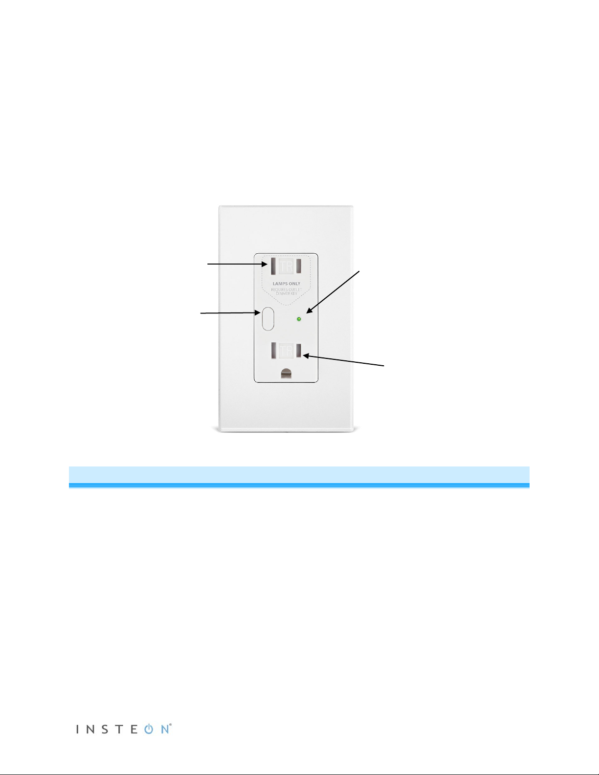
About OutletLinc Dimmer
LED
Uncontrolled
outlet
Set button
Controlled
The award-winning OutletLinc Dimmer is the most elegant remote-control lamp dimmer in the world. The
top outlet gives you INSTEON remote and automatic control of dimmable lamps up to 300 watts. The
bottom outlet is a standard, always-on 15 amp receptacle. Because OutletLinc is dual-band, it also acts
as an Access Point for battery-powered INSTEON devices, as well as a wireless electrical p has e br idge.
Plus, it comes with the Outlet Dimmer Key, a razor-thin piece that fits over lamp plugs and prevents nondimmable loads from being plugged into—and possibly damaging—the remote-controlled top outlet.
outlet
“Always On”
Features and Benefits
• Elegant, built-in, clean and professional look for remotely controlling lamps
• One remotely-controllabl e outlet and one standard (alwa ys on) outlet with a total load capac ity of 15
Amps
• Remote-controlled outlet handles incandescent lamps up to 300W
• Tamper-resistant: ETL-tested s hutter m echanism for protecti on against improper objec t insertion and
electric shock. Conforms to NEC Article 406.11
• Load sense enabled on remote-controlled outlet (manually switching load on/off will turn outlet on/off)
• Auto-off temperature sensor
• Dual-band: communicates simultaneously over both radio frequency (RF) and the powerline
• Functions as an Access Point for RF-only devices
• Functions as an electric al phase bridge
• Local on/off control via Set button
• Remotely controls other INSTEON devices
Page 2 of 13 2472D - Rev: 1/21/2014 7:48 AM
Page 3

• X10 compatible
dimming INSTEON on/off switch. USER ASSUMES ALL RISKS ASSOCIATED WITH
install OutletLinc for you. If you have any questions, please consult an electrician or call 800-762-7845.
• Beeper and dual-color LED for easy setup
• 32 brightness levels and ramp rates
• All settings saved in non-volatile memory, even through power outages
• Wires into standard J-box exactly the same as a standard outlet
• Comes with the innovative Outlet Dimmer Key
• Two-year warranty
What’s in the Box?
• OutletLinc Dimmer
• Outlet Dimmer Key
• Three wire nuts
• Quick Start Guide
Installation
CAUTIONS AND WARNINGS
Read and understand these instructions before installing and retain them for future reference.
OutletLinc is intended for installation in accordance with the National Electric Code and local regulations in the United States or t he
Canadian Electrical Code and local regulations in Canada. Use indoors only. OutletLinc is not designed nor approved for use on
power lines other than 120V 60Hz, single phase. Attempting to use OutletLinc on non-approved power lines may have hazardous
consequences.
• Use only indoors or in an outdoor-rated box
• Be sure that you have turned off t he circuit breaker or removed the fuse for t he circuit you are installing OutletLinc in.
Installing OutletLinc with the power on will expose you to dangerous voltages.
• Connect only copper or copper-cl ad wire to OutletLinc
• OutletLinc may feel warm during operation. The amount of heat generated is within approved limits and poses no
hazards. To minimize heat buildup, ensure that the area surrounding the rear of OutletLinc is as clear of clutter as
possible.
• Each OutletLinc is assigned a unique INSTEON ID, which is printed on the device’s label.
• To reduce the risk of overheating and possible dam age to other equipment, use OutletLinc’s dimmer outl et to control no
more than 300 Watts of 110VAC incandescent lamps only. Dimming an inductive load, such as a fan or transformer, c ould
cause damage to the dimmer, the load bearing device, or both. If the manufacturer of the load device does not
recommend dimming, use a nonDIMMING AN INDUCTIVE LOAD.
• You will need a flathead screwdriver, a Philips screwdriver and a voltage meter to install OutletLinc Dimmer
Identifying the Electrical Wires in your Home
To install OutletLinc, you will need to identify the following four wires:
• Line - usually black, may also be called Hot or Live, carries 110VAC electricit y into the outlet
• Neutral - usually white
• Ground - bare copper wire or metal fixture (if grounded)
If you are having difficulties identifying wires, consult an electrician to help you.
IMPORTANT: If you are not knowledgeable about or and comfortable with elect rical circuit ry, you should have a qualified electric ian
Page 3 of 13 2472D - Rev: 1/21/2014 7:48 AM
Page 4
Magnet
1) Turn off the circuit breaker (or remove fuse) supplying power to the outlet location.
2) Remove the existing wallplate from the outlet you are replacing. Then, unscrew the outlet itself and
pull it out from the junction box.
3) Disconnect the wires from the outlet you are replacing. If the wires cannot be detached by unscrewing
them, cut the wires where they enter the switch and then strip ½” of insulation off the ends.
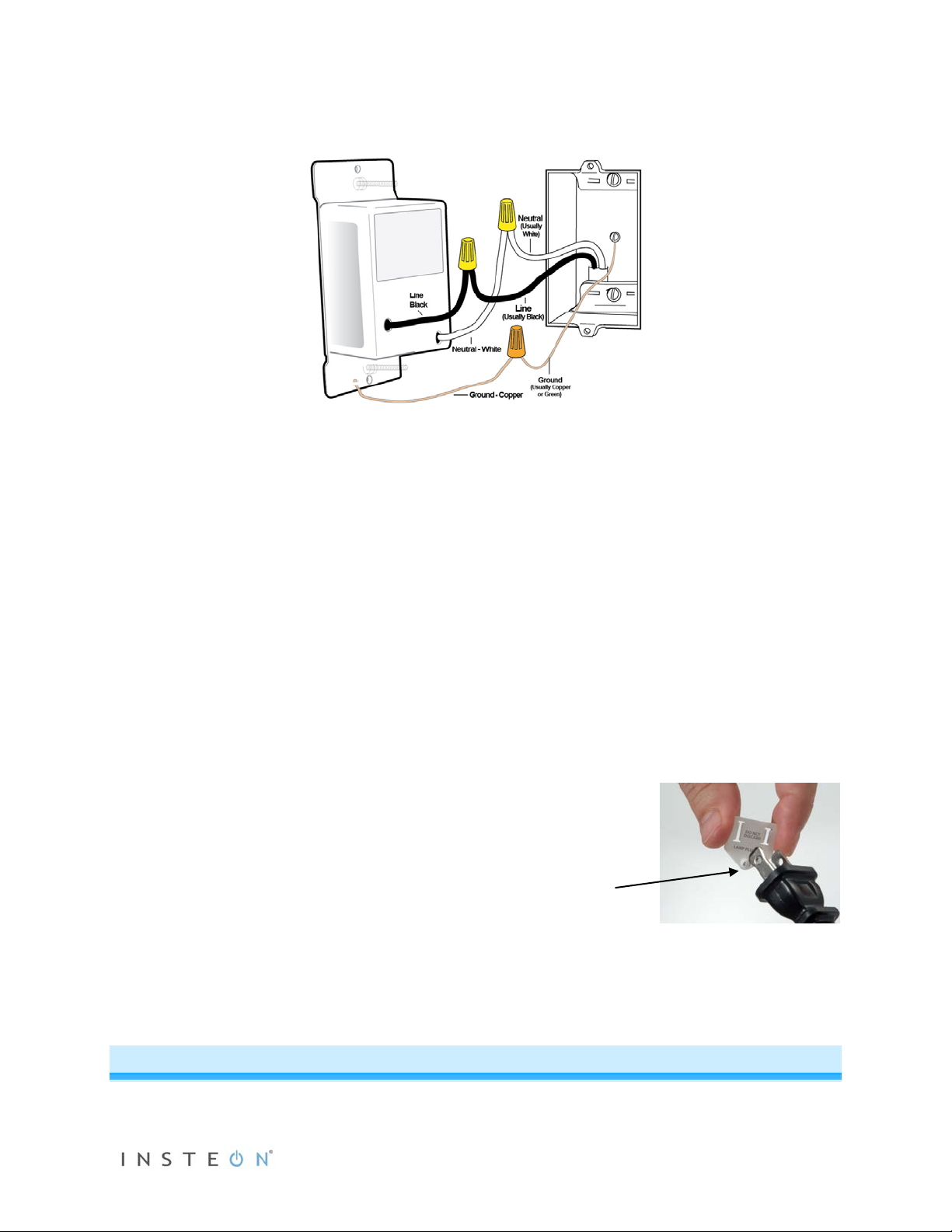
4) Twist together the bare copper OutletLinc wire to the Ground wire with a wire nut.
5) Twist together the white OutletLinc wire to the Neutral wire with a wire nut.
6) Twist the black OutletLinc wire to the Line wire with a wire nut.
7) Ensure all connections are solid with no exposed copper (other than Ground).
8) Carefully inst a ll and screw OutletLinc into electrical box, then install Decora trim-plate.
9) Turn circuit breaker back on.
OutletLinc LED will blink red for about 1 minute then turn solid red.
10) Slip the OutletLinc Dimmer Key over the prongs of
your lamp’s plug so the circular magnet protrusion
faces the lamp’s plug.
11) Plug lamp into top outlet on OutletLinc.
The lamp will turn on and the OutletLinc LED will
turn on green.
12) If the lamp does not turn on, turn it on manually using
the lamp’s switch.
13) Tap OutletLinc’s Set button.
Lamp will turn off (if on) and on (if off).
LED will be green when lamp is on and red when it is off.
(faces plug)
Local Control and Status
Page 4 of 13 2472D - Rev: 1/21/2014 7:48 AM
Page 5

Set Button
LED
Steady-on green
Load is on (at any dim level)
Steady-on red
Load is off
Blinking red slowly
Device is plugged in without Dimmer Key installed, or
Dimmer Key removed from OutletLinc (10 seconds), or
Dimmer Key missing and INSTEON message received, or
OutletLinc Dimmer is overheating
Optional blink-on-traffic is turned on,
Dimmer off and INSTEON traffic received
Optional blink-on-traffic is turned on,
Dimmer on and INSTEON traffic received
Tap the Set button to toggle connected lamp on and off. Press and hold (as per instructions) to manage
other properties and INSTEON scenes (as per instructions below)
Load Sense
If outlet is off, then turning on the connected load (e.g. lamp) via manual adjustment (e.g. rotating lamp’s
on/off knob) will result in the outlet turning on.
Beeper
- Single beep: transition from one setup mode to another
- Double-beep: successful scene addition or removal
- Continuous beeps for 3 seconds: unsuccessful scene management or 4-minute setup timeout
LED
and blinking red quickly
and blinking green quickly
Setting up INSTEON Scenes
One or more INSTEON responders that respond to an INSTEON controller create an INSTEO N scene. When the scene is ac tivated (devices turned on), all devices return to the stat es they were at wh en the scene was programmed.
INSTEON scenes let you activate dramatic whole-room c hanges at the touch of a button. For example,
you can set all the lights in a sc ene to dim to 50% or tur n certai n lights o n whil e tur ning oth ers of f, all with
the tap of a single INSTEON controller button.
INSTEON scenes are easy to set up; just follow the directions below.
Adding OutletLinc to a Scene as an INSTEON Responder
1) Plug lamp into bottom outlet and use lamp’s switch to turn it on.
2) Plug lamp (with dimmer key installed) into top outlet.
Page 5 of 13 2472D - Rev: 1/21/2014 7:48 AM
Page 6

LED will turn green.
3) Press and hold the scene controller button until it beeps.
1
Controller’s LED will blink.
4) Press and hold OutletLinc’s Set butt on until it double-beeps.
OutletLinc’s LED will flash once and return to green.
Controller will double-beep
2
and its LED will stop blinking.
5) Confirm that scene addition was successful by tapping on then off on the controller’s scene button.
The light plugged into OutletLinc will toggle on and off.
6) If you wish to adjust the light’s scene on-level and/or ramp rate:
a. Using your scene controller, adjust t he light’s brightness to correspond with the ramp rate
desired (see Setting the Ramp Rates
for more information).
b. Double-tap OutletLinc’s Set button.
OutletLinc will beep once.
c. Using your scene controller, adjust the light’s brightness to the des ired brightness (on-
level) for your scene.
d. Return to Step 3.
Removing OutletLinc From a Scene as an INSTEON Responder
If you are going to discontinue using O utl etL inc , i t is v ery important that you remove it from all of its scene
controllers. Otherwise, the controllers will retry commands repetitively and creating network delays.
3
1) Press and hold the controller’s scene button until controller beeps.
Controller’s LED will begin blinking.
2) Press and hold the Scene button until Controller beeps again.
4
Controller’s LED will continue blinking.
3) Press and hold Set button on OutletLinc until it double -beeps.
OutletLinc’s LED will flash once and return to steady green (or red).
Controller’s LED will stop blinking.
4) Confirm that unlinking was successful by tapping the button you just unlinked from on the controller.
OutletLinc will no longer respond.
Advanced Features
Changing the LED Brightness (or Turning Off LED)
1) Press and hold Set button until it beeps.
LED will blink green.
1
If the controller does not have a beeper, wait until its LED begins blinking.
2
Most models
3
For devices without beepers, hold until LED begins blinking (this may take 10+ seconds).
4
For devices without beepers, hold until LED begins blinking (this may take 10+ seconds).
Page 6 of 13 2472D - Rev: 1/21/2014 7:48 AM
Page 7

2) Press and hold Set button until it beeps again.
LED will blink red.
3) Press and hold Set button until it beeps a third time.
LED will stop blinking and its intensity will be equal to that of the connected lamp.
4) Use an OutletLinc scene controller of OutletLinc to adjust the LED to the desired brightness.
5) Once you have reached the desired LED brightness, tap the Set button
OutletLinc will beep once and return to ready mode.
Setting On-Level
On-level is the brightness level at wh ich the light you are control ling will turn on. The default on-level is
100%, but is adjustable from off to 100% brightness.
OutletLinc's on-le ve l ca n b e as s ig ned to a c on trol ler a s par t of a s c en e (s ee
Adding OutletLinc t o a Scen e
as an INSTEON Responder). The on-level for local control can only be adjusted via software.
Setting the Ramp Rate1
The ram p rate is the tim e it tak es the OutletLinc Dimmer load to transition from full-off to full-on (and vice
versa). The default ramp rate is 0.5 seconds, but is adjustable from 0.1 seconds to 9 secon ds (locally at
OutletLinc Dimmer) or 9 minutes (via software such as HouseLinc*), with 32 ramp rates available.
1) Ramp rate is set using the load’s brightness level as an indicator for the ramping speed. Using an
OutletLinc scene controller, adjust the load to the brightness le ve l wh ic h corresponds to the desired
ramp rate using this table:
Desired Ramp Rate in Seconds2 Brightness Level
Instant 100%
0.2 seconds 85%
0.3 seconds 70%
0.5 seconds (default) 55%
2 seconds 45%
4.5 seconds 30%
8.5 seconds 5%
2) Once you reach the appropriate brightness, double-tap OutletLinc’s Set button.
OutletLinc will beep.
3) Wait 4 minutes before changing any other settings on OutletLinc Dimmer.
*Note: you may set ramp rates of up to 9 minutes via INSTEON compatible software.
1
Setting the ramp rate does not change or affect the on-level brightness.
2
If the load is ramping to less than full brightness, then the time it will take will be proportionately less. For instance, if the load is going to half-brightness, the time it will take for
a given ramp rate will be halved.
Page 7 of 13 2472D - Rev: 1/21/2014 7:48 AM
Page 8

Using OutletLinc as a Phase Bridge
OutletLinc automatically bridges the e lectrical phas es in your home (via communications with dual-band
devices on the opposite phase). Use the following procedure to confirm that the phases are bridged:
1) Start Phase Bridging Detection Mode by tapping the Set button on OutletLinc four times quickly
OutletLinc will begin beeping and LED will be green.
2) Check the LED beha vior of the other dual-band device s. If they are not blink ing green,
1
try relocating
the other device.
3) If the “other” dual-band device is blinking green
2
the devices are within range and on opposite
phases) tap OutletLinc’s Set Button
LED will return to green
if load is on, or turn red if load is off.
Adding OutletLinc to a Scene as an INSTEON Controller
Follow the steps below if you wish to use OutletLinc as a scene controller via its Set button.
1) Tap the Set button (if present) on the responder you wish to control until it is on.
2) If desired, adjust the responder load to the state you wish it t o be at when the scene is activate d fr om
OutletLinc (e.g. 50%, 25% or even off).
3
3) Press and hold OutletLinc’s Set button until it beeps.
OutletLinc’s LED will blink green.
4) Press and hold the responder’s Set button until it beeps and/or LED flashes.
OutletLinc will double-beep and its LED will stop blinking.
5) Confirm that scene addition was successful by tapping the Set button on OutletLinc
The responder will respond appropriately.
6) If you wish to link multiple responders to OutletLinc, repeat steps 1-4 with for each responder.
Removing OutletLinc from a Scene as an INSTEON Controller
If you are no long er going to us e an IN ST EON res ponder that OutletLinc controls, it is very im portant th at
you remove its scene membership. Otherwise, OutletLinc will retry every scene command repetitively,
creating network delays.
1) Tap the button or Set button on the responder you wish to remove.
2) Press and hold the OutletLinc’s Set button until it beep s .
OutletLinc’s LED will blink green.
3) Press and hold OutletLinc’s Set button until it beeps again.
OutletLinc’s LED will blink red.
4) Press and hold the responder’s Set button until it double-beeps and/or its LED blinks.
OutletLinc will double-beep and its LED will stop blinking.
5) Confirm that unlinking was successful by tapping the S et button on OutletLinc.
The responder will no longer respond.
1
Or not blinking at all for single colored LEDs
2
Or not blinking at all for single colored LEDs
3
If the responder is a multi-scene device, tap the scene button you wish to control until its LED is in the desired state (on or off).
Page 8 of 13 2472D - Rev: 1/21/2014 7:48 AM
Page 9

General
OutletLinc Dimmer - INSTEON Remote Control Dimmer Outlet
Brand
Smarthome
Manufacturer Product Number
2472D
White - 2472DWH: 813922010251
Blink LED on INSTEON Traffic
This feature can be enabled (and subsequently disabled) via compatible software packages.
Beep on Local Set Button Presses
This feature can be enabled (and subsequently disabled) via compatible software packages.
Factory Reset
The factory reset proc edure clears all se ttings f rom OutletLinc, including INSTEON links, on-levels, ramp
rates, X10 addresses, etc.
1) If possible, remove all scene memberships prior to performing the factory reset.
2) Turn off circuit breaker.
3) Press and hold OutletLinc’s Set button. Do not let go.
4) Have a friend turn on the circuit breaker.
As you continue to press and hold, OutletLinc will begin to emit a long beep.
5) When beep stops, release Set button.
The OutletLinc LED will turn on solid green and then turn off.
After a few seconds, OutletLinc will double-beep.
LED state depends upon other factors (see the LED status table
X10 Programming
Instructions on setting X10 primary address and scene addresses can be found online:
http://www.smarthome.com/insteon-x10-programming.html
Specifications
Product Name
UPC
for more information).
(Dual-Band)
Almond - 2472DAL: 813922010220
Light Almond - 2472DL AL : 8139 220 116 30
Black - 2472DBK: 813922010237
Gray - 2472DGY: 813922011364
Ivory - 2472DIV: 813922 01 0244
Brown - 2472DBR: 813922011357
Page 9 of 13 2472D - Rev: 1/21/2014 7:48 AM
Page 10

FCC ID
SBP2472D
Patent Number
7,345,998 US, International Patents Pending
Warranty
2 Years, Limited
INSTEON
INSTEON ID
1
INSTEON
256 responder groups and 1 controller group
Brightness Levels
32 (256 with software)
Maximum Scene Links
400
Scene Commands Supported as
On
Off
On
Off
Press and Hold Bright
Press and Hold Dim
Incremental Bright
Incremental Dim
Fast On
Fast Off
Software Configurable
Yes, Always
RF Range
150’ Open air
X10 Support
Yes
X10 Addresses
1 max, unassigned by default
INSTEON Device Category
INSTEON Device Subcategory
INSTEON Product Key (IPK)
Mechanical
Mounting
Wires
White - Neutral
Bare Copper - Ground
Case Color
White
Set Button
1, color matched to unit
Plastic
UV Stabilized Polycarbonate
Beeper
Yes
LED
Dual Color, Green and Red
Dimensions
4.1" H x 1.73" W x 1.73" D
Weight
120 grams / 0.26 pounds
Operating Environm ent
Indoors
Operating Temperature Range
32-104 F
Thermal Overload Protection
Controller
Scene Commands Supported as
Responder
Wires
0x01 Dimmable Lighting Control
0x21
0x000068
Standard, single gang wall box
3, 14 gauge
Black - Hot
Page 10 of 13 2472D - Rev: 1/21/2014 7:48 AM
Disables controlled outlet until condition resolved and operated
Page 11

with ON command or front button push.
Operating Humidity Range
0-85% Relative Humidity
Electrical
Voltage
120VAC +/- 10%, Split, Single Phase
Frequency
60Hz
Maximum Dimmer Load
300 Watts
Load Type(s)
Incandescent
Surge Resistance
Up to 500 VAC
Retains all settings without power
Yes, all saved in Non-volatile EEPROM
Standby power consumption
< 1 watt
Safety Approved
ETL (Intertek Testing Services)
Certifications
FCC, IC Canada
Problem
Possible Cause
Solution
Protect Feature – OutletLinc protects
devices are plugged in.
Make sure circ uit breaker is on.
Check the junction box wires to ensure all
exposed.
The controller m ay have dropped out of
device.
Make sure phases are bridged. Add additional
INSTEON devices .
Large appliances, such as refrigerators
electrical noise on the powerline.
Other electrical devices, such as
may be absorbing the I N STEON signal.
The controller m ay be sending
unused responder are being resent and
Unlink any unused responders from the controller.
membership and eli minate unnecessary links.
Troubleshooting
Controlled load turns off
for a moment when I plug
a device into the bottom
outlet.
LED won’t come on. OutletLinc is not get ting power.
OutletLinc won’t add to
scene as a responder.
The controller turns
OutletLinc off, but not on.
its controlled load circuitry by
momentarily turning the controlled load
off when certain types of high-inrush
linking mode or linked to another
The INSTEON signal m ay not be
getting to the “vicinity” of OutletLinc.
or air conditioners, may be produci ng
computers, televisions or power strips,
Ramp rate may be extremely slow.
OutletLinc may be li nked at off.
Leave your device plugged in, or try plugging your
device into another outlet.
connections are tight and no bare wires are
Try relinking OutletLinc to the controller.
INSTEON devices and/or move around existing
Install a power l ine noise filter (FilterLinc #1626-10)
to filter electrical noise and minimize signal
attenuation.
Relink to controller with a faster Ramp Rate. See
Setting the Ramp Rat e.
Press the Set button once to turn on the lamp, t hen
relink with the contr oller.
OutletLinc is taking a long
time to respond to a
controller.
Page 11 of 13 2472D - Rev: 1/21/2014 7:48 AM
commands to a different responder that
is no longer in use. C om m ands for the
HINT: If you are using home automation software
such as HouseLinc, you can easily check scene
Page 12

Problem
Possible Cause
Solution
slowing down communication signals to
OutletLinc.
If the above doesn’t w ork, perform a factory reset
on the controller.
The load turned on by
The load doesn’t appear to
turn on right away.
Remove power to Outl etLinc by turning off the
on. If that doesn’t w ork, perform a factory reset.
Be sure the protruding magnet of the Outlet Dimmer
plug of the load. See I nstalling OutletLinc Dimmer.
itself.
Another controller, a timer or stray X10
signals could have triggered OutletLinc.
The OutletLinc sensed a change in the
connected table lamp and triggered the
load sense feature.
Monitor for recurrence and remove reason if you
can determine what it is. If necessar y perform a
factory reset.
Disable load sense (via compatible sof tware such
as HouseLinc) or m ake sure a standard
incandescent bulb is used.
The ramp rate may be set too slow. Set a faster ramp rate. See Setting the Ramp R ate.
OutletLinc is l ocked up.
An LED bulb plugged i nto
OutletLinc does not turn
off completely when I send
an OFF command.
The OutletLinc LED is
blinking red even though I
haven’t put it into unlinking
mode.
A surge or excessive noise on the
power line may have glitched it.
Since LEDs requir e so little power, the
load sensing current that runs through
OutletLinc may be en ough to power the
bulb.
The Outlet Dimmer Key m ay not be
properly instal led.
circuit breaker for five seconds, then t urning it back
Add to the load with more LEDs or higher wattage
bulbs, generally higher than a 5 Watt load.
Add one incandesc ent bulb to soak up the s ense
current.
Key faces away from OutletLinc and towar ds the
Be sure the Outlet Dimmer Key lies completely flush
against OutletLi nc.
If you have tried t hese solutions, review ed this Owner’s Manual, and still cannot r esolve an issue you are having with
OutletLinc, pl ease call the INSTEON Support Line at 800-762-7845
Certification and Warranty
Certification
This product has been tho roughl y tested by ITS ETL SE MKO, a nationall y re cogni zed indepe ndent third-party testin g laborat ory. The North American
ETL Listed mark signifies that the device has been test ed to an d has met the requi rements o f a widel y recogni zed consens us of U.S. and Canadian
device sa fety sta ndards, t hat the m anuf acturing s ite has b een audi ted, an d that th e manuf acture r has agr eed to a program of quart erly factory foll owup inspections to verify continued conformance.
FCC and Industry Canada Compliance Statement
This device complies with FCC Rules Part 15 and Industr y Ca na da RSS-210 (Rev. 7). Operation is subject to the following two conditions:
(1) This device may not cause harmful interference, and
(2) This device must accept any interference, including interference that may cause undesired operation of the device.
Le present appareil e st c o nf orm e a u x CNR d' Ind us tri e C a na da appli c ables aux appareils radio exempts de licence. L'exploitati on es t aut ori s e a u x deux
conditions suivantes:
(1) l'appareil ne doit pas produire de brouillage, et
(2) l'utilisateur de l'appareil doit accepter tout brouillage radiolectrique subi, mme si le brouillage est susceptible d'en compromettre le
fonctionnement.
The digital circuitry of this device has been tested and found to comply with the limits for a Class B digital device, pursuant to Part 15 of the FCC Rules.
These limits are designed to pro vide reasonable protection agai nst harmful inte rference in resid ential installatio ns. This equipm ent generates, uses,
and can radiate radio freque ncy energ y and, if not installe d and used in acco rdance with the instruct ions, may cau se harmful inte rference to ra dio and
television reception. However, there is no guarantee that interference will not occur in a particular installation. If this device does cause such
interference, whic h ca n be ve ri fie d by turning the device off a nd o n, th e us e r is enc o ur age d to eli m ina t e th e inte rf e re nce b y o ne o r m ore of th e fol lo wi ng
measures:
- Re-orient or relocate the receiving antenna of the device experiencing the interference
- Increase the distance between this device and the receiver
- Connect the device to an AC outlet on a circuit different from the one that supplies power to the receiver
- Consult the dealer or an experienced radio/TV technician
WARNING: Chang es or m odificati ons t o this device not expr essly ap proved by th e part y responsi ble for compli ance c ould voi d the us er’s a uthorit y to
operate the equipment.
Page 12 of 13 2472D - Rev: 1/21/2014 7:48 AM
Page 13

ETL / UL Warning (Safety Warning)
CAUTION: To reduce t he risk of overheating and possible damage t o other equipment, do n ot install this device to control a receptacl e, a motor-
operated appliance, a fluorescent lighting fixture, or a transformer-su ppl i ed ap pl ianc e.
Gradateurs comman dant une lampe a filam ent de tungstene – afin de redui re le risqué de surchau ffe et la possibilite d’en dommagement a d’ autres
materiels, ne pas install er pour comm a nde r une pri se, un ap pa rei l a mot eur , une l am pe flourescente ou un appareil alimente par un transformateur.
Limited Warranty
Seller warrants t o the original consumer pur chaser of thi s product th at, for a period of two years from the date of purcha se, this prod uct will be f ree
from defects in mate rial and workmanship a nd will perform in substan tial conformity to the descri ption of the product i n this Owner’s Manual. T his
warranty shall not appl y to defec ts or errors caus ed by misuse o r neglect. If the product is f ound to be defective in material or workmanshi p, or if the
product does not perform as warr anted above during the warranty peri od, Seller will either repair it, replace it, or ref und the purchase pric e, at its
option, upon receip t of the p roduct at t he addr ess belo w, pos tage p repai d, with pr oof of th e date of purcha se and a n e xplana tion of th e defec t or e rror.
The repair, replacem ent, or refund that is provided for abov e shall be the full extent of Seller’s lia bility with respect to this product . F or repair or
replacement durin g the war ra nty period, call the INSTEON Gol d Su pp ort Line at 800-762-7845 with the Model # and Revision # of the device to receive
an RMA# and send the product, along with all other required materials to:
INSTEON
ATTN: Receiving
16542 Millikan Ave.
Irvine, CA 92606-5027
Limitations
The above warrant y is in lieu of and Seller discl aims all other warranties, w hether oral or written, express or implied, including any warr anty or
merchantability or fitness for a p articular pur pose. Any implie d warranty, incl uding any warra nty of mercha ntability or fit ness for a partic ular purpose,
which may not be disclaimed o r suppl ante d as provid ed ab ove shall be lim ited to the t wo-year of the e xpress wa rranty above. No other repres entation
or claim of any nature by any person shall be binding upon Seller or modify the terms of the above warranty and disclaimer.
Home automation devices have the risk of failure to operate, incorrect operation, or electrical or mechanical tampering. For optimal use, manually verify
the device state. Any home automation device should be viewed as a convenience, but not as a sole method for controlling your home.
In no event shall Seller be liable f or special, inci dental, conseque ntial, or other dam ages resulting f rom possession or use of this device, incl uding
without limitation damage to prop ert y a nd, to t he e xt ent p erm i tte d by law, personal inj u r y, even if Seller kne w or should have kno wn of the possibility of
such damages. Som e st at es d o n ot all ow limitations on how l on g an im pl i ed warranty lasts and/or the exclusion or l im i tation of d am age s, i n whi ch c as e
the above limitations and/or exclusions may not apply to you. You may also have other legal rights that may vary from state to state.
Protected under U.S. and foreign patents (see www.insteon.com)
© Copyright 2012 INSTEON, 16542 Millikan Ave., Irvine, CA 9260 6, 800-762-7845, www.insteon.com
Page 13 of 13 2472D - Rev: 1/21/2014 7:48 AM
 Loading...