

Page 1
ApplianceLinc
Model :
2456SE
INSTEON® Outdoor Plug-In Applianc e On/Off Module
Page 2

ApplianceLinc Owner’s Manual
TABLE OF CONTENTS
ABOU T APP L IANCELI N C ........................................................................................................................... 3
Key ApplianceLinc Features ...................................................................................................................... 3
What is Included with ApplianceLinc ......................................................................................................... 3
WHAT IS INSTEON? .................................................................................................................................... 4
INSTALLATION ............................................................................................................................................ 5
Preparing to Install ApplianceLinc ............................................................................................................. 5
Installing ApplianceLinc ............................................................................................................................. 6
USING APPLIANCELINC ............................................................................................................................. 7
LED and Beeper Activity ............................................................................................................................ 7
CONTROLLING APPLIANCELINC FROM AN INSTEON CONTROLLER ................................................ 8
Linking an INSTEON Controller to ApplianceLinc ..................................................................................... 8
Unlinking ApplianceLinc from an INSTEON Controller ............................................................................. 8
CREATING INSTEON SCENES................................................................................................................... 8
ADVANCED FEATURES ............................................................................................................................. 9
Enabling/Disabling Lo ad Sens in g .............................................................................................................. 9
Restoring Power to ApplianceLinc ............................................................................................................ 9
Resetting ApplianceLinc to its Factory Default Settings ............................................................................ 9
X10 PROGRAMMING OPTIONS ............................................................................................................... 10
Setting the X10 Primary Address ............................................................................................................ 10
Removing the X10 Primary Address ....................................................................................................... 10
ADVANCED X10 PROGRAMMING OPTIONS .......................................................................................... 11
Remotely Setting an X10 Scene Address ............................................................................................... 11
Remotely Removing an X10 Scene Address .......................................................................................... 11
ABOUT INSTEON ...................................................................................................................................... 12
Using Dual-Band INSTEON Devices to Upgrade Your Network ............................................................. 12
Important Note about INSTEON Networks; Split Single-Phase vs. 3-Phase Installation........................ 12
Further Enhancing Reliability .................................................................................................................. 12
ADDITIONAL RESOURCES ...................................................................................................................... 12
TROUBLESHOOTING ................................................................................................................................ 13
SPECIFICATIONS, CERTIFICATION, AND WARRANTY ........................................................................ 14
Specifications .......................................................................................................................................... 14
Certification .............................................................................................................................................. 14
Limited Warranty ..................................................................................................................................... 14
Page 3
ApplianceLinc Owner’s Manual
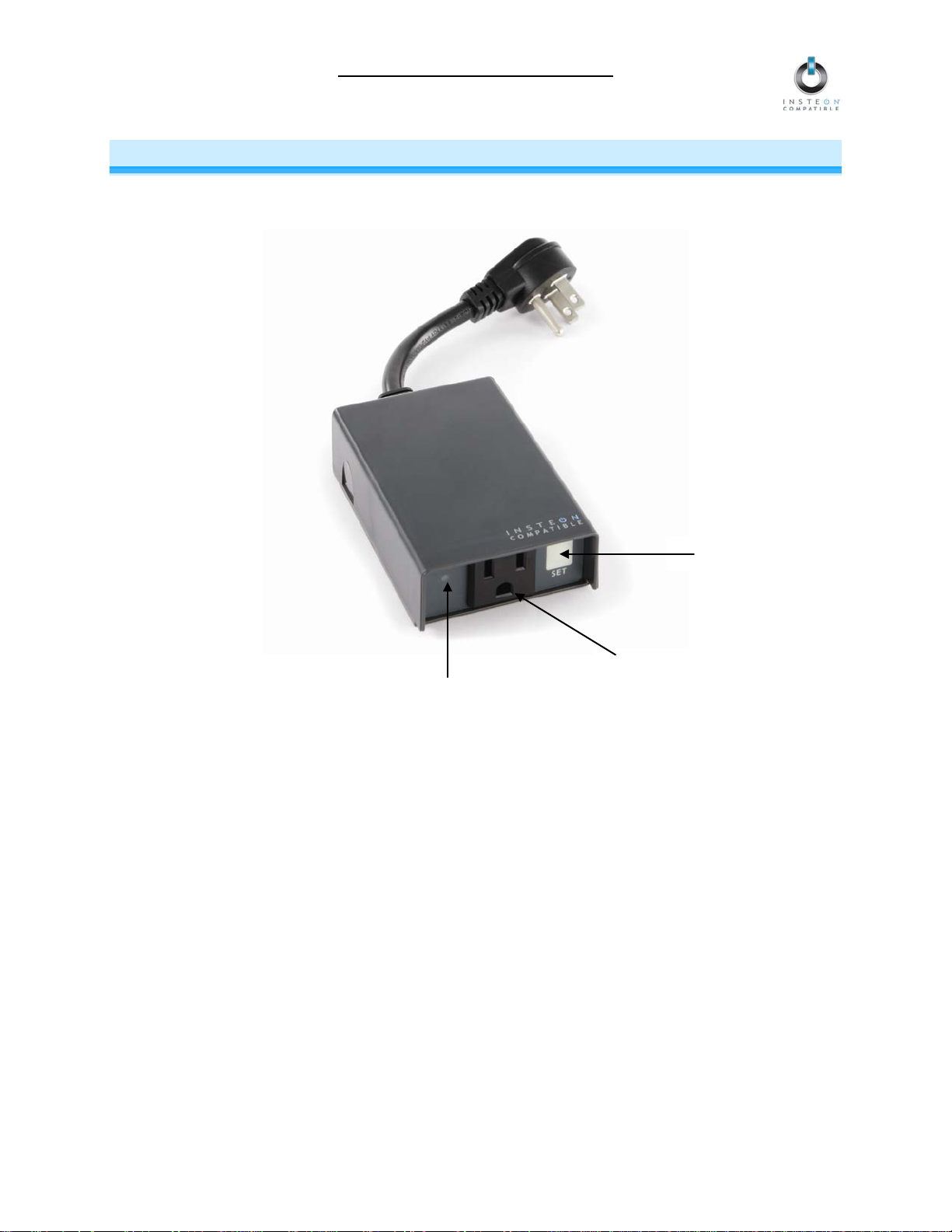
Outlet
Status LED
Set button
ABOUT APPLIANCELINC
ApplianceLinc present s you with an elegant and s tylish way to rem otely control any pl ug-in device in and
outside your home at the touch of a button. Send commands to ApplianceLinc from any INSTEON
Controller.
Key ApplianceLinc Features
• Installs and Links to other INSTEON devices in minutes
• Controls standard incandescent loads up to 1800 Watts and inductive loads up to 15 Amps
• Weatherproof to withstand harsh outdoor conditions
• Indicates INSTEON setup mode activity and operational states with a dual-color Status LED and
beeper
• Load Sensing easily disabled and re-enabled
• Responds to commands from X10 controllers
• Stores setup state in memory so settings aren’t lost during power outages
• Two-year warranty
What is Included with ApplianceLinc
• ApplianceLinc – INSTEON Outdoor Plug-In Appliance On/Off Module
• Quick-Start Guide
Page 3 of 14
Page 4

ApplianceLinc Owner’s Manual
WHAT IS INSTEON?
Since its inception in 2005, INSTEON has become a best-selling home-control networking technolog y,
offering more reliability and flexibility than any other home management system on the market. INSTEON
systems are sim ple, reliable, a nd affor dable. Simple, because each device tak es mere minutes to install.
Reliable, because ever y INST EON dev ice work s as a network repeater, e nsurin g your c omm ands will not
be lost. Affordable, bec ause INST EON can be int egrated i nto any num ber of devic es easil y and at a very
low cost. An INSTEON home grows in value with each added INSTEON device, making life more
convenient, safe, and fun.
How Does INSTEON Work?
What makes INST EON the most reliable hom e automation network is its dual-mesh net work. INSTEON
devices use both radio frequenc y (RF) signals and the hom e’s existing wiring to talk to each other. In an
INSTEON network, every INSTEON device also acts as a repeater, receiving and sending every
message to all other devices in the network. So by integrating more INSTEON devices you will strengthen
the network and ensure no commands will be lost.
No central controller or networking setup is required with an INSTEON network. Simply install your
devices and th en use a series of button presses or taps to Link your devices together. Throughout this
Owner’s Manual, you may see the terms “Controller” or “Responder”. These generic INSTEON terms
refer to the components of an INSTEON scene, and are used on a scene-by-scene basis.
• Controller – sends INSTEON commands to other devices
• Responder – reacts to commands sent out by another INSTEON device
An INSTEON device may act as a Controller, Responder, or sometimes both.
INSTEON network s are also extremely secure. Each INSTEON device is assigned a unique INSTEON
ID, so unless neighbors or would-be hackers have acces s to your particular device’s INST EON ID, they
won’t be able to control your home, even if they are using similar products.
Page 4 of 14
Page 5

ApplianceLinc Owner’s Manual
INSTALLATION
Preparing to Install ApplianceLinc
CAUTION
Read and understand these instructions before installing and retain them for future reference.
ApplianceLinc is intended for installation in accordance with the National Electric Code and local
regulations in the United States or the Canadian Ele ctrical Code and local regulations in Canada. Use
indoors only. ApplianceLinc is not designed nor approved for use on po wer lines other than 120V 6 0Hz,
single phase. Attempting to use ApplianceLinc on non-approved power lines may have hazardous
consequences.
Prior to installing ApplianceLinc, please review the entire installation procedure and take the following
precautions:
• Don’t plug ApplianceLinc into an outlet controlled by a switch because if the switch is
inadvertently turned off, ApplianceLinc won’t have power
• Don’t plug ApplianceLinc into a filtered power strip or AC line filter
• Be sure the device’s built-in switch is in the on position
• Be sure ApplianceLinc is connected to a 3-prong AC outlet that incl udes a Ground Fault Circuit
Interrupt (GFCI) f eature. If Applianc eLinc is plugged into an o utlet w ithout GF CI prot ection, m ake
sure there is a GFCI d evice upstream (at another ou tlet closer to the electric al panel or a GFCI
circuit breaker).
• Test your GFCI protection eac h time ApplianceLinc is plugged in, as well as on a mont hly basis.
To test your GFCI pro tection, make sure Appl ianceLinc is plugged in and the connected load is
on. Then, push the TEST button on the GFCI outlet or circuit breaker. This unit must stop
operating. Wait abo ut 5 seconds and the n push the RESET button on the GFCI outlet or circuit
breaker. Appliance Linc will begin receiving e lectricity and the con nected load will turn on. If the
GFCI circuit does not p erform in this manner , there may be an e lectrical malfunction , increasing
the probability of electric shock. Disconnect the power until the problem has been corrected.
Please see the instructions that came with your GFCI device for specific testing procedures.
When in doubt of the GFCI device’s ability to detect a ground fault, replace the GFCI device.
• Don’t bury Appliance Linc , a n y elec tric a l cabl e, or component connected to it. A bur ied p ower cord
may result in electrocution if improper cables are used or if digging occurs over the cable.
• Don’t allow vegetation to grow on or around ApplianceLinc
• Don’t install ApplianceLinc in a manner that allows water to accumulate around it
• Don’t exceed the load rating of ApplianceLinc. Check and add up all the electrical devices that will
be attached and make sure the total does not exceed 15 Amps.
• Don’t use any electrical cord or extension cord that is damaged or in poor condition
• If an extension cord is used, the cord must be properly grounded. Be sure the extension cord is of
adequate capacity to provi de power to your load. A “light-dut y” or “medium-duty” extension c ord
may cause a voltage drop, which will cause overheating of the cable, plug, or socket.
• Don’t attempt to open ApplianceLinc. The case is sealed and can’t be opened. There are no user-
serviceable parts inside.
• Don’t use ApplianceLinc to control devices that preserve, maintain, or contribute to human or
animal safety or life support
If you have any questions, please call:
INSTEON Gold Support Line
800-762-7845
Page 5 of 14
Page 6

ApplianceLinc Owner’s Manual
Installing ApplianceLinc
1) Plug the appliance/device (also called the load) you want to control into the outlet on ApplianceLinc
2) Plug ApplianceLinc into an unswitched wall outlet
The ApplianceLinc Status LED will turn on solid green
If the load does not turn on, tap the Set button on Applianc eL inc
3) Allow ApplianceLinc to hang down from the outlet so it is facing down
NOTE: After com pleting installation, you will not be able to use the load’s built-in switc h to control the
load, unless you have enabled the Loa d Sens i ng feat ure. See Enabling/Disabling Load Sensing.
Page 6 of 14
Page 7

ApplianceLinc Owner’s Manual
LED Activity
ApplianceLinc Status/Setup Mode
Solid green
Load is on
Solid red
Load is off
Blinking green
Linking Mode
Blinking red
Unlinking Mode
Beeper Activity
ApplianceLinc Status
Entered setup mode or moved to the subsequent setup mode
Exited setup mode (if Set button was tapped)
Feature was programmed
Double beep
Link established – ApplianceLinc will exit setup mode
Long beep
Timed out of setup mode
USING APPLIANCELINC
LED and Beeper Activity
LED Activity
Tapping the Set Button
If ApplianceLinc is in a setup mode, tap the Set button to exit the setup mode and return to normal
operation.
Beeper Activity
Single beep
Page 7 of 14
Page 8

ApplianceLinc Owner’s Manual
CONTROLLING APPLIANCELINC FROM AN INSTEON CONTROLLER
Linking an INSTEON Controller to ApplianceLinc
To use ApplianceLinc as an INSTEON Responder, follow these steps to Link ApplianceLinc and a
Controller together. R efer to the Control ler’s Owner’s Manu al for detailed i nstructions on ho w to properly
install and Link it to ApplianceLinc.
The following will work for the most common INSTEON devices:
1) Use the Set button to set ApplianceLinc to the state you wish to activate from the Controller (on or off)
2) Set the Controller to Linking Mo de. (For m ost Contr ollers, pr ess & hold an On or Scene butt on for 10
seconds or the Set button for 3 seconds.)
You will have 4 minutes to complete the next step before Linking Mode automatically times out.
3) Press & hold the Set button on ApplianceLinc until it double-beeps (3 seconds)
The ApplianceLinc Status LED will turn on solid green if the load is on or solid red if it is off
4) Confirm that Linking was successful by tapping the button you just Linked to on the Controller
ApplianceLinc will respond appropriately
Unlinking ApplianceLinc from an INSTEON Controller
If you are going to disconti nue using ApplianceLinc, it is very important that you Unlink it from any Linked
Controllers. Otherwise, the Controllers will retry any commands repetitively, thus slowing down the
system.
The following will work for the most common INSTEON devices:
1) Set the Controller to Unlinking Mode. ( For most Controllers, press & hold an On or Sc ene button f or
10 seconds twice or the Set button for 3 seconds twice.)
You will have 4 minutes to complete the next step before Unlinking Mode automatically times out.
2) Press & hold the Set button on ApplianceLinc until it double-beeps (3 seconds)
The ApplianceLinc S tatus L ED will turn on solid green if the load is on or solid red if it is off
3) Confirm that Unlinking was successful by tapping the button you just Unlinked from on the Controller
ApplianceLinc will no longer respond
CREATING INSTEON SCE NE S
INSTEON scenes let you activate dramatic lighting moods with the tap of just one butt on. For example,
you can set all the lights in a scene to dim to 50% or tur n certai n lights o n whil e turnin g other s of f, all wit h
the tap of a button on a Controller.
INSTEON scenes are ver y easy to set up – just Link more than one Resp onder to the same On/Off or
Scene button on a Controll er. Then, when you tap any of the Link ed buttons on the Controller , all of the
INSTEON devices Linked in the scene will respond as a group.
Page 8 of 14
Page 9

ApplianceLinc Owner’s Manual
ADVANCED FEATURES
Enabling/Disabling Load Sensing
Load Sensing allows you to manually turn on the load plugged into ApplianceLinc by using the switch on
the load itself, without sendin g a command from an INSTEON or X10 controller. When the load is in the
off state (with Load Sensing enabled), ApplianceLinc wil l “sense” that you ar e trying to turn it o n with its
built-in switch. When ApplianceLinc senses this, it will turn on the load automatically.
CAUTION: W ith Load Sensing, some loads have been k nown to turn on ApplianceLinc af ter you have
turned it off. Please use this feature with caution.
By default, Load Sensing is disabled.
Enable Load Sensing
1) Press & hold the Set button on ApplianceLinc until it beeps (3 seconds)
The ApplianceLinc Status LED will begin blinking green
2) Triple-tap the Set button on Applianc e Linc
The ApplianceLinc Status LED will stop blink ing and turn on solid green if t he load is on or s olid
red if it is off
3) Test that Load Sensing has been enabled by turning the load on and off from its built-in switch
The load will turn on and off
Disable Load Sensing
1) Press & hold the Set button on ApplianceLinc until it beeps (3 seconds)
The ApplianceLinc Status LED will begin blinking green
2) Double-tap the Set button on ApplianceLinc
The ApplianceLinc Status LED will stop blink ing and turn on solid green if t he load is on or s olid
red if it is off
3) Test that Load Sensing has been enabled by turning the load on and off from its built-in switch
The load will not respond
Restoring Power to ApplianceLinc
ApplianceLinc stores all of its settings, such as Links to other INSTEON devices, with non-volatile
memory. Because set tings are saved in t his non-volatile memory, they will not be lost in t he event of a
power failure.
In the event of a power los s ApplianceLinc will automatically return the load to th e brightness lev el it had
before power was interrupted.
Resetting ApplianceLinc to its Factory Default Settings
The factory reset procedure can be used to clear the ApplianceLinc memory of all INSTEON Links,
programmed On-Levels and Ramp Rates, X10 addresses, etc.
1) If you are using a Controller to control ApplianceLinc, be sure t o Unlink it from the Controller. See
Unlinking ApplianceLinc from an INSTEON Controller.
2) Unplug ApplianceLinc for about 10 seconds
3) While holding do wn the Set but ton on Applia nceLinc, plu g it back in, making sur e not to let go of the
Set button
ApplianceLinc will beep and its Status LED will turn on solid green
4) Continue to hold down the Set button for 3 seconds and then release
The ApplianceLinc Status LED will flash red and then turn on solid green
After a few seconds, the load will turn on
Page 9 of 14
Page 10

ApplianceLinc Owner’s Manual
X10 PROGRAMMING OPTIONS
ApplianceLinc is X10 ready, meaning that it can respond to X10 commands from X10 controllers.
However, to operate ApplianceLinc in X10 mode, you m ust first set up an X10 Primar y Address. As it
ships from the factory or after a factory reset procedure, ApplianceLinc will not have an X10 Primary
Address set up.
Setting the X10 Primary Address
1) Set ApplianceLinc to Linking Mode by pressing & holding the Set button for 3 seconds
The ApplianceLinc S tatus L ED will begin blinking green
You will ha ve 4 m inutes to complete the next step before Linking Mode automatically times out.
2) Using an X10 controller, send the X10 address you want to assign and the ON command three times
For example, to assign the address A1, you would send “A1 ON A1 ON A1 ON.”
3) Once ApplianceLinc has received the sequence, it will exit Linking Mode
ApplianceLinc will double-beep
The ApplianceLinc S tatus L ED will turn on solid green if the load is on or solid red if it is off
Removing the X10 Primary Address
If you are no longer going to control ApplianceLinc with an X10 P ri m ar y Addr ess, it is very im portant that
you Unlink it . Ot her wise, ApplianceLinc will still respond to X1 0 comm ands and m ay cause ApplianceLinc
to turn on by itself.
1) Set ApplianceLinc to Linking Mode by pressing & holding the Set button for 3 seconds
The ApplianceLinc Status LED will begin blinking green
2) Set ApplianceLinc to Unlinking Mode by pressing & holding the Set button for 3 seconds
The ApplianceLinc S tatus L ED will continue blinking red
You will have 4 minutes to complete the next step before Unlinking Mode autom atic all y tim es out.
3) Using an X10 controller, send the X10 address you wish to remove and the ON command three
times
For example, to remove the address A1, you would send “A1 ON A1 ON A1 ON”.
4) Once ApplianceLinc has received the sequence, it will exit Linking Mode
ApplianceLinc will double-beep
The ApplianceLinc S tatus L ED will turn on solid green if the load is on or solid red if it is off
Page 10 of 14
Page 11

ApplianceLinc Owner’s Manual
O16
N16
M16
P16
M16
M16
N16
O16
P16
O16
N16
M16
P16
M16
O16
P16
M16
N16
ADVANCED X10 PROGRAMMING OPTIONS
ApplianceLinc can be a mem ber of up to 255 X10 scenes. An X10 scene address is just another X10
address like the X10 Pr imary Address. When an X10 ON comm and is sent to an X10 scene address,
every X10 device with that addres s will turn on to its indepe nde nt O n-L ev el at its i ndep end ent Ramp Rate
(if a dimmable device). Sending an X10 OFF com mand to an X10 sc ene address wi ll turn off all devices
that are members of that X10 scene, each at its independent Ramp Rate. Dimmable X10 devices will
react to DIM and BRIGHT c ommands after the X10 scene addr ess is sent. However, th ey will ignor e ALL
ON and ALL OFF commands for the X10 scene address.
Remotely Setting an X10 Scene Address
1) Using an X10 controller, send the CLEAR sequence:
2) Use the Set button on ApplianceLinc to set the load to the desired state (on or off)
3) Send the following X10 address sequence:
4) Send the desired X10 scene address (house code and unit code)
Remotely Removing an X10 Scene Address
1) Using an X10 controller, send the CLEAR sequence:
2) Send the ApplianceLinc’s X10 Primary Address (house code and unit code)
3) Send an X10 ON or OFF command
4) Send the following X10 address sequence:
Send the X10 scene address you w ish to remove (house code and unit code)
Page 11 of 14
Page 12

ApplianceLinc Owner’s Manual
ABOUT INSTEON
Using Dual-Band INSTEON Devices to Upgrade Your Network
What are phases?
The majority of single-family homes in North America have two phases (or “legs”) of 110 Volts coming into their
electricity panels. From the panel, they are distributed throughout the home, providing power to outlets and wall
switches. These phases come together in some parts of the home to provide 220 Volts of power to large
appliances, such as an electric oven or pool pump.
Why do I need to bridge these phases?
Single-band power line devices send commands via the home’s electricity, but only on a single phase. If the
command is intended for a device on the opposite phase, there is a good chance the command will go
unnoticed. Installing dual-band INSTEON devices, such as Access Points (#2443), on each phase will allow for
devices to communicate between the two phases via RF.
Dual-band INSTEON devices embody the full potential of a true INSTEON mesh network. Taking the power
line band signal and working in conjunction with the RF band signal, its dual-band function plays out in two
ways:
• Phase bridger – a receiver of commands, reacting to and translating signals sent from one power
phase to the opposite via RF
• Signal repeater – a participant in an INSTEON network, repeating commands intended for other
devices whether those commands are generated from RF or power line-only devices. To ensure
reliability, every INSTEON device confirms that it has received a command. If a Controll er does not
receive this confirmation, it will automatically retransmit the command up to five times.
While using at least one dual-band device is required when using an RF-only device, at least two dual-band
devices are recommended in any INSTEON network to ensure reliable communication across two-phase home
wiring systems. For larger applications, it is recommended to install at least one dual-band device for every 750
– 1,000 square feet.
Search for dual-band INSTEON devices at: www.smarthome.com/dualband
Important Note about INSTEON Networks; Split Single-Phase vs. 3-Phase Installation
For the best INSTEON network performance, be sure you have properly installed at least two dual-band
INSTEON devices. INSTEON has only been officially tested in a split single-phase residential environment but
has been known to work in many 3-phase systems, where three dual-band devices are used (one on each
phase). However, due to the potential complexity of its troubleshooting, the INSTEON Gold Support Line is
unable to support INSTEON in 3-phase environments.
Further Enhancing Reliability
As signals travel via the power line or RF throughout the home, they naturally beco me weaker the farther they
travel. The best way to overcome weakened signals is to increase the coverage of the mesh network by
introducing more INSTEON devices.
It is possible that some audio-video devices, computers, power strips, or other electrical equipment may
attenuate INSTEON signals on the power line. You can temporarily unplug suspected devices to test whether
the INSTEON signal improves. If it does, then you can plug in filters that will permanently fix the problem.
ADDITIONAL RESOURCES
Find home automation solutions, helpful tips, interactive demos, videos, user forums, and more at the
Smarthome Learning Center: www.smarthome.com/learningcenter.html
Page 12 of 14
Page 13

Problem
Possible Cause
Solution
The Controller or might have
ApplianceLinc from it.
The Controller and
opposite power line phases.
Add additional INSTEON devices or move around
INSTEON network repeaters.
Large appliances, such as
the power line.
Other electrical devices, such
signal.
If the above doesn’t work, perform a factory reset on the
Controller.
Another Controller, a timer, or
If the above doesn’t work, perform a factory reset. See
Resetting ApplianceLinc to its Factory Default Settings.
The load is not being
ApplianceLinc.
TROUBLESHOOTING
The Status LED on
ApplianceLinc is not
turning on and won’t
control the load.
ApplianceLinc may not be
getting power.
ApplianceLinc Owner’s Manual
Make sure ApplianceLinc is not plugged into a switched
outlet that is turned off.
ApplianceLinc won’t Link
or work with a Controller.
ApplianceLinc is taking a
long time to respond to a
Controller.
been reset without Unlinking
ApplianceLinc may be on
The INSTEON signal may be
too weak.
refrigerators or air
conditioners, may be
producing electrical noise on
as computers, televisions, or
power strips, may be
absorbing the INSTEON
The Controller may be
sending commands to a
Responder that is no longer
in use. Commands for the
unused Responder are being
resent and loading down the
signal.
Re-Link ApplianceLinc to the Controller.
Make sure two dual-band INSTEON devices are
properly installed to bridge the two power line phases.
existing INSTEON devices. All INSTEON devices act as
Install a power line noise filter (#1626-10) to filter
electrical noise and minimize signal attenuation.
Unlink any unused Responders from the Controller.
HINT: If you are using home automation software, you
can easily check scene membership and eliminate
unnecessary Links.
The load turned on by
itself.
The Controller can turn
off ApplianceLinc but
ApplianceLinc does not
turn on when I send an
ON command from the
Controller.
ApplianceLinc is locked
up.
controlled by
If you have tried these solutions, reviewed this Owner’s Manual, and still cannot resolve an issue you are having with
ApplianceLinc, please call:
stray X10 signals could have
triggered ApplianceLinc.
ApplianceLinc may be Linked
at its off state.
A surge or excessive noise
on the power line may have
glitched it.
The load may not be getting
power.
Perform a factory reset. See Resetting ApplianceLinc to
its Factory Default Settings.
Re-Link ApplianceLinc to the Controller, while the load is
on. See Linking an INSTEON Controller to
ApplianceLinc.
Unplug ApplianceLinc for 10 seconds and then reinstall.
Make sure the load’s manual switch is in the on position.
INSTEON Gold Support Line
800-762-7845
Page 13 of 14
Page 14

ApplianceLinc Owner’s Manual
SPECIFICATIONS, CERTIFICATION, AND WARRANTY
Specifications
View specifications for ApplianceLinc at: www.smarthome.com/2456S3E.html
Certification
This product has been thorough ly tested b y ITS ETL SEMKO, a nationall y recognized indep endent thirdparty testing laborator y. The North Am erican ET L Lis ted m ark s ignifies tha t the device has been tes ted t o
and has met the requirements of a widely recognized consensus of U.S. and Canadian device safety
standards, that the manufacturing site has been audited, and that the manufacturer has agreed to a
program of quarterly factory follow-up inspections to verify continued conformance.
Limited Warranty
Seller warrants to the original consumer purchaser of this product th at, for a period of t wo years fr om th e
date of purchase, this product will be free from defects in material and workm anship and will perform in
substantial conform ity to the description of the product in this Owner’s Ma nual. This warranty shall not
apply to defects or er rors caused b y misuse or neg lect. If the product is f ound to be def ective in m aterial
or workmanship, or if the product does not perf orm as warranted ab ove duri ng the warra nty peri od, Sel ler
will either repair it, re place i t, or ref und th e purchas e pric e, at its opt ion, up on rec eipt of the prod uct at th e
address below, postage pr epaid, with proof of the date of purchase and an explanation of the defect or
error. The repair, replacement, or refund that is provided for above shall be the full extent of Seller’s
liability with respect to this product. For repair or replacement during the warranty period, call the
INSTEON Gold Support Line at 800-762-7845 with th e Model # and Revision # of the device to receive
an RMA# and send the product, along with all other required materials to:
Smarthome, Inc.
ATTN: Receiving Dept.
16542 Millikan Ave.
Irvine, CA 92606-5027
Limitations
The above warranty is in lieu of and Seller disclaims all other warranties, wheth er oral or written, express
or implied, including any warranty or merchantability or fitness for a particular purpose. Any implied
warranty, including an y warranty of merchantabilit y or fitness for a part icular purpose, which may not be
disclaimed or supplanted as provided above shall be limited to the two-year of the express warranty
above. No other representation or claim of any nature by any person shall be binding upon Seller or
modify the terms of the above warranty and disclaimer.
Home automation devices have the risk of failure to operate, incorrect operation, or electrical or
mechanical tam pering. For optimal use, manuall y verify the device state. Any h ome automation device
should be viewed as a convenience, but not as a sole method for controlling your hom e.
In no event shall Seller be liable for special, incident al, consequential, or other dam ages resulting from
possession or use of this device, including without limitation damage to property and, to the extent
permitted by law, personal injury, even if Seller knew or should have known of the possibility of such
damages. Some states do not allow limitations on how long an implied warranty lasts and/or the exclusion
or limitation of dam ages, in which c ase the abo ve lim itations and/or exclus ions m ay not app l y to you. You
may also have other legal rights that may vary from state to state.
INSTEON Technology Patent
U.S Patent No. 7,345,998, International patents pending
© Copyright 2011
Smarthome, 16542 Millikan Ave., Irvine, CA 92606, 800-762-7845, www.smarthome.com
Rev 06-03-2011
Page 14 of 14
 Loading...