

Page 1
DIN Rail Dimmer
Owner’s Manual
2452-222 (US)
2452-422 (EU)
2452-522 (AUS/NZ)
Page 1 of 19 2452-222/2452-422/2452-522 - Rev: 1/21/2014 7:50 AM
Page 2

About DIN Rail Dimmer ................................................................................................................................................. 3
Installation Preparation ................................................................................................................................................ 3
Identifying the Electrical Wires in Your Home (North America only) ........................................................................... 3
Identifying the Electrical Wires in Your Home (Europe/Australia/New Zealand) ......................................................... 3
Identify Switch Type...................................................................................................................................................... 4
Installation ..................................................................................................................................................................... 4
Switch Operation Mode ................................................................................................................................................ 5
Change Mode .............................................................................................................................................................. 5
3-Way Toggle Mode (Latching Switches Only, Default) ............................................................................................ 5
Local Control Operations ............................................................................................................................................. 6
Latching Wall Switch (Default) ..................................................................................................................................... 6
Single Momentary Wall Switch .................................................................................................................................... 6
Dual Momentary Wall Switch ....................................................................................................................................... 6
Adjust Local Settings.................................................................................................................................................... 6
Local On-Level ............................................................................................................................................................. 6
Local Ramp Rate ......................................................................................................................................................... 7
Resume Dim ................................................................................................................................................................ 7
Change LED Brightness (or turn it off) ........................................................................................................................ 8
Error Blink .................................................................................................................................................................... 8
INSTEON Setup ............................................................................................................................................................. 8
INSTEON Controllers, Responders and Links ............................................................................................................ 8
Make DIN Rail a Responder ........................................................................................................................................ 9
Make DIN Rail a Controller .......................................................................................................................................... 9
Groups ......................................................................................................................................................................... 9
Scenes ......................................................................................................................................................................... 9
Make DIN Rail a Controller of Multiple Responders .................................................................................................. 10
Remove DIN Rail as a Controller (Unlink) ................................................................................................................. 10
Remove DIN Rail as a Responder (Unlink) ............................................................................................................... 10
Remove DIN Rail as a Controller of Multiple Responders (Unlink) ........................................................................... 10
Factory Reset ............................................................................................................................................................ 11
X10 Setup ..................................................................................................................................................................... 11
Assign an X10 Address ............................................................................................................................................. 11
Remove X10 Address ................................................................................................................................................ 11
Specifications .............................................................................................................................................................. 12
Troubleshooting .......................................................................................................................................................... 15
Phase Bridge Detect Beacon/RF Range Test ........................................................................................................... 17
Replacing Fuse .......................................................................................................................................................... 17
Certification and Warranty ......................................................................................................................................... 18
Certification ................................................................................................................................................................ 18
FCC and Industry Canada Compliance Statement ................................................................................................... 18
Declaration of Conformity .......................................................................................................................................... 18
ETL/UL Warning (Safety Warning) ............................................................................................................................ 18
Limited Warranty ........................................................................................................................................................ 18
Limitations .................................................................................................................................................................. 19
Page 2 of 19 2452-222/2452-422/2452-522 - Rev: 1/21/2014 7:50 AM
Page 3
electrical circuitry, you should hav e a qualified electrician install the product for you.
Tools Needed
Optional
Accessories
Slotted screwdriver
INSTEON Hub
Wire cutter/stripper
Mini Remote
Voltage Meter
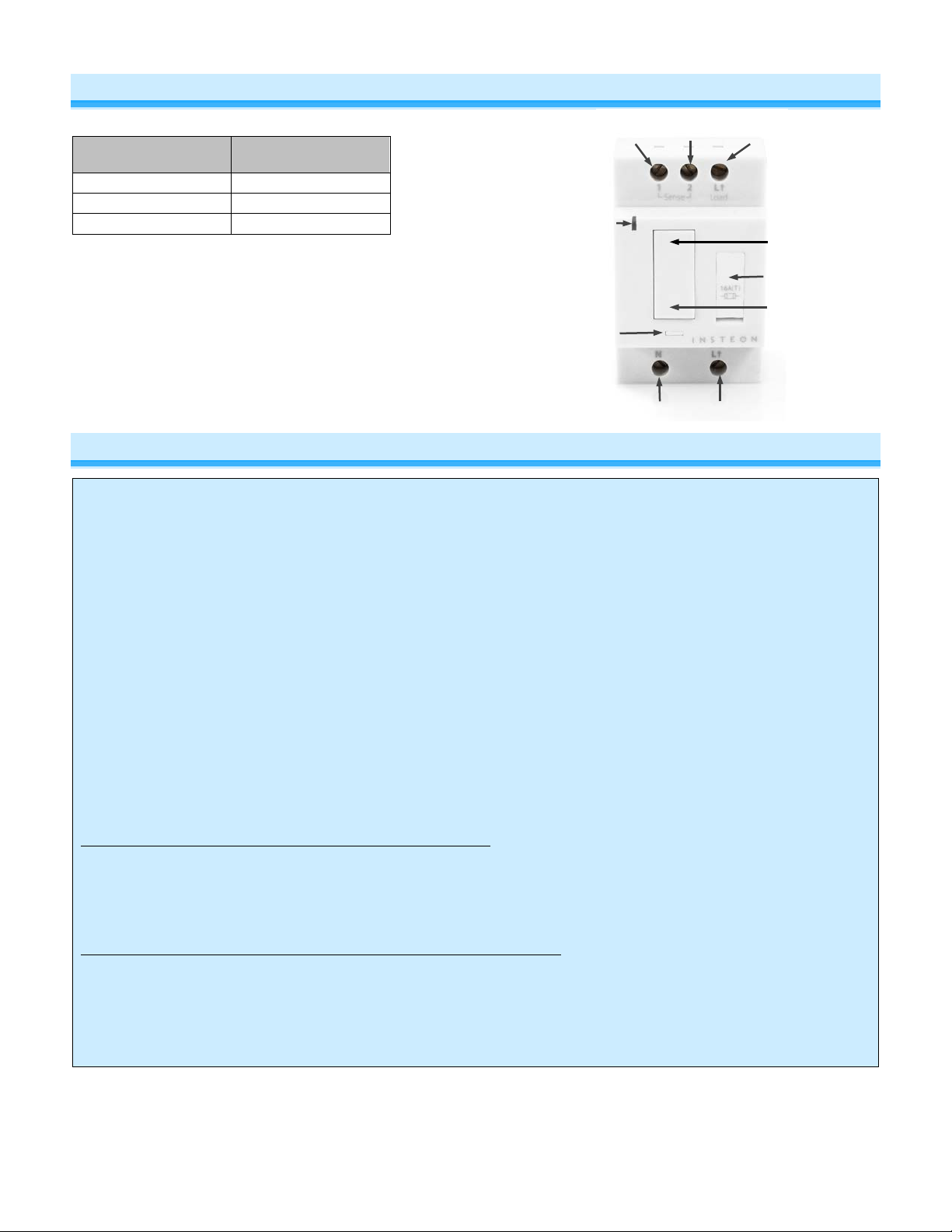
Line
Neutral
Paddle top
(on/brighten)
LED
Fuse (US Only)
Set
Sense #2
Connected
load
Sense #1
Paddle bottom
(off/dim)
About DIN Rail Dimmer
button
Installation Preparat ion
CAUTIONS AND WARNINGS
Read and understand these instructions before installing and retain them for future reference.
This product is intended for installation in accordance with the local regulations in the regions intended for sale. Use indoors
only. This product is not designed or approved for use on power lines other than 100-277VAC,50Hz or 60Hz, single phase.
Attempting to use this product on non-approved power lines may have hazardous consequences.
- Use only indoors or in outdoor rated box
- Be sure that you have turned off the circuit breaker or removed the fuse for the circuit you are installing this product into.
Installing this product with the power on will expose you to dangerous voltages.
- Connect using only copper or copper-clad wire
- This product may feel warm during operation. The amount of heat generated is within approved limits and poses no
hazards. To minimize heat buildup, ensure the area surrounding this product is as clear of clutter as possible.
- Each INSTEON product is assigned a unique INSTEON I.D., which is printed on the product’s label.
- To reduce the risk of overheating and possible damage to other equipment, do not use this product to control loads in
excess of the specified maximum(s) or, install in locations with electricity specifications which are outside of the product’s
specifications. If this device supports dimming, please note that dimming an inductive load, such as a fan or transformer,
could cause damage to the dimmer, the load bearing device, or both. If the manufacturer of the load device does not
recommend dimming, use a non-dimming INSTEON on/off switch. USER ASSUMES ALL RISKS ASSOCIATED WITH
DIMMING AN INDUCTIVE LOAD.
Identifying the Electrical Wires in Your Home (North America only)
- Line: usually black (may also be called hot, live or power), carries 100-277VAC electricity into the wall box
- Neutral: usually white or white wire bundle, commonly daisy-chained from box to box
- Load: usually black, from a separate cable jacket
- Ground: bare copper wire or metal fixture (if grounded)
Identifying the Electrical Wires in Your Home (Europe/Australia/New Zealand)
- As wire colors vary from country to country, make sure you always check your electrical wires with a voltage meter to
correctly identify line, load, neutral and ground wires
IMPORTANT!
If you have any difficulties or questions, consult an electrician. If you are not knowledgeable about, and comfortable with,
Page 3 of 19 2452-222/2452-422/2452-522 - Rev: 1/21/2014 7:50 AM
Page 4

Identify Switch Type
Before you install DIN Rail behind a switch, you must determine which type of switch you have—latching (the default
setting), single momentary or dual momentary—as each is wired differently. If you are using DIN Rail with a single
momentary or dual momentary switch, you will program it for the corresponding switch after installation.
• Latching (default mode): switch has no central position: it can be pressed on both the top and bottom and
remains in that state once released
• Single momentary: switch can only be pressed in one place (like a doorbell) and returns to central position
once released
• Dual momentary: switch can be pressed on both the top and bottom; returns to central position once
released
Installation
1) Turn off breaker/fuse and verify power is off
2) Disconnect wires from light fixture. Strip away wire coating until you have 5/16” (8mm) of bare wire on the ends.
3) After ensuring the wires are not touching, turn on breaker/fuse
4) Use a voltage meter to identify the fixture’s line, load and neutral wires, then turn off breaker/fuse again
5) For reference, write down the INSTEON I.D. (on the side of the module) and the load it is controlling
6) Snap module onto DIN rail. (If installing next to another module, allow 3/4" (2 cm) between modules for heat
dissipation.)
7) Connect wires per diagram which corresponds to your installation
Note: sense lines carry very low current (~0.35mA 240V, ~0.17mA for 120V)
8) After ensuring wires are firmly connected and that there is no exposed wire, turn on breaker/fuse
After a few seconds, load will turn on and DIN Rail LED will turn green
9) Test by tapping DIN Rail paddle top and bottom
Load will turn on and off
DIN Rail LED will turn green when load is on and red when load is off
Page 4 of 19 2452-222/2452-422/2452-522 - Rev: 1/21/2014 7:50 AM
Page 5

Switch Operation Mode
By default, DIN Rail is programmed for a latching switch. If you are installing DIN Rail behind a single momentary or
dual momentary switch, you must change DIN Rail’s local-control switch operation to single momentary mode or dual
momentary mode.
Change Mode
1) If installing a single momentary or dual momentary switch, change mode as follows
a) Press and hold set button until it beeps
LED will start blinking green
b) Press and hold set button until it beeps a second time
LED will start blinking red
c) Press and hold set button until it beeps a third time
LED will start blinking green
d) Perform the step that applies
• For single momentary: slowly tap set button four times
LED will continue blinking green
• For dual momentary: slowly tap set button five times
LED will start double-blinking green
• To switch back to latching: slowly tap set button six times
LED will start blinking green
e) Once the mode is selected, press and hold set button until it double-beeps
LED will stop blinking and turn green if load is on or red if load is off
2) Test mode change by following the switch actions in the Latching, Single Momentary, or Dual Momentary tables
below
Load will respond appropriately
3-Way Toggle Mode (Latching Switches O nly, Default)
Because DIN Rail module comes programmed for latching switches, 3-way toggle mode is enabled by default.
Normally, a latching switch reads the switch’s up position as on and down position as off. For example, if you turn
DIN Rail module on from the latching switch and off from another controller, the switch is still in the up (on) position;
turning DIN Rail module back on from the switch would require you to tap the switch down, then up again.
The 3-way toggle mode overrides this sense feature, so in that same scenario—turning DIN Rail module on at the
switch and off from another controller, so switch is in up (on) position—you could then turn DIN Rail module on at the
switch by tapping it down.
If you are installing DIN Rail module behind a single or dual momentary switch, 3-way t oggle mode is ignored. If
desired, you can disable (or re-enable) 3-way toggle mode by performing these steps:
1) Press and hold set button until it beeps
LED will start blinking green
2) Press and hold set button until it beeps a second time
LED will start blinking red
3) Press and hold set button until it beeps a third time
LED will start blinking green
4) Press and hold set button until it beeps a fourth time
LED will start blinking red
5) Tap set four times button
DIN Rail module will beep
LED will start dou ble-blinking red
6) Press and hold set button until it double-beeps
LED will stop blinking
3-way toggle mode is now disabled (or re-enabled)
Page 5 of 19 2452-222/2452-422/2452-522 - Rev: 1/21/2014 7:50 AM
Page 6
Connected load/responders
Latching switch
Tap
LED
Connected load/responders
Single momentary switch
Tap
Press and hold
Double-tap
LED
on/off)
Connected load/responders
Dual momentary switch
Tap
Press and hold
Double-tap
LED
Local Control Operati ons
DIN Rail’s switch operation mode affects how it responds to commands; so it’s important to properly program DIN
Rail for the correct type of switch you are installing. DIN Rail on/off buttons function exactly like the top and bottom of
your wall switch.
Note: LED will blink red for a few seconds if one or more responders do not acknowledge a mess age.
Latching Wall Switch (Default)
Single Momentary Wall Switch
Switch
Top
Bottom
On/Off
(ramped)
On
(ramped)
Off
(ramped)
Brighten/Dim
(until release or full-
Green
Red
On/Off
(instant)
Green/
Red
Dual Momentary Wall Switch
Top
Bottom
On
(ramped)
Off
(ramped)
Brighten
(until release or 100%)
Dim
(until release or off)
On
(instant)
Off
(instant)
Green
Red
Adjust Local Settings
Local On-Level
Local on-level is the brightness that the loa d wir ed into DIN Rail will come on when turned on at the DIN Rail paddle.
The default local on-level is 100% brightness, but it can be set to any one of 32 fixed brightness levels (3% to 100%).
If you want DIN Rail to turn the load on at its last brightness level (prior to being turned off), see Resume Dim
1) Press and hold set button until it beeps
LED will start blinking green
2) Press and hold set button until it beeps a second time
LED will start blinking red
.
Page 6 of 19 2452-222/2452-422/2452-522 - Rev: 1/21/2014 7:50 AM
Page 7

Ramp Rate Presets
“Instant”
0.5 seconds
2 seconds
5 seconds
3) Press and hold set button until it beeps a third time
LED will start blinking green
4) Press and hold set button until it beeps a fourth time
LED will start blinking red
5) Slowly tap set butt on onc e
LED will start double-blinking red
6) Press and hold DIN Rail on/off buttons to dim and brighten load to desired brightness
7) Press and hold set button until it double-beeps
LED will stop blinking
LED will turn green
8) Test by turning switch off and then back on
Load will turn on to new local on-level
Local Ramp Rate
The local ramp rate is the time it takes for the connected load to go from off to 100% brightness. The default ramp
rate is 0.5 seconds, but is adjustable from instant to 5 seconds (using set button) or up to 8 minutes (with software).
Note: if your local on-level is less than 100% brightness, the ramp rate will be shortened depending on the brightness
level. For example, if you program a 2-second ramp rate for a load that has a local on-level of 50% brightness, it will
take 1 second for the load to ramp from off to 50% brightness.
1) Press and hold set button until it beeps
LED will start blinking green
2) Press and hold set button until it beeps a second time
LED will start blinking red
3) Press and hold set button until it beeps a third time
LED will start blinking green
4) Press and hold set button until it beeps a fourth time
LED will start blinking red
5) Slowly tap set button 2 times
LED will continue blinking red
6) Press and hold set button to see the next available ramp rate
Load will ramp from off to on at the next available ramp rate
LED will continue blinking red
7) To see the next ramp rate, press and hold set button again
Load will ramp from off to on at the next available ramp rate
8) If this is the desired ramp rate, tap set button to accept
DIN Rail will doub l e beep and the LED will stop blinking
(factory default)
9) Test by turning off and then back on via the local switch
Load will ramp off and back on at the new local ramp rate
Resume Dim
When resume dim is enabled, each time you turn on the DIN Rail it will go to the previously used dim level. T o
change the desired level, simply dim or brighten to the new desired level and turn the DIN Rail off. When you turn it
on again it will return to the last used dim level.
1) Press and hold set button until it beeps
LED will start blinking green
Page 7 of 19 2452-222/2452-422/2452-522 - Rev: 1/21/2014 7:50 AM
Page 8

Controller
Responder
Link
2) Press and hold set button until it beeps a second time
LED will start blinking red
3) Press and hold set button until it beeps a third time
LED will start blinking green
4) Press and hold set button until it beeps a fourth time
LED will start blinking red
5) Slowly tap set button three times
LED will start double-blinking red
6) Press and hold set button until it double-beeps
LED will stop blinking
7) Test by turning off and then back on via the local switch
Load will ramp off and back on to resume dim level
Change LED Brightness (or turn it off)
DIN Rail’s LED is set at a default 50% brightness, but it can be set anywhere from off to 100% brightness by
following these steps.
1) Press and hold set button until it beeps
LED will start blinking green
2) Press and hold set button until it beeps a second time
LED will start blinking red
3) Press and hold set button until it beeps a third time
LED will start blinking gree n
4) Tap set button once
LED will start double-blinking green
5) Press and hold set button until it beeps
LED will turn green (at brightness of connected load)
6) Press and hold DIN Rail on/off buttons to brighten or dim LED to desired brightness
7) Tap set button until it double-beeps
DIN Rail will double beep and return to ready mode
Error Blink
By default, DIN Rail LED blinks red for a few seconds to acknowledge a communication error with a responder. This
setting is adjustable via software or central controller only.
INSTEON Setup
Some products have subtle differences in their setup procedures. Please refer to the other device’s owner’s manual
for details.
INSTEON Controller s, R es pon der s and Li nk s
Let’s define a few terms.
• The INSTEON “transmitter” is called a controller
• The INSTEON “receiver” is called a responder
Note: Some devices are controllers only (e.g., motion sensors, handheld remotes), some are responders only (e.g.,
FanLinc), and some can be controllers and responders (e.g., switches and dimmers).
• The association between the controller and responder is called a link
Note that a link is one way. If you want control the other way (making the responder a controller), and the devices are
capable of it, simply add a link “the other way.”
Page 8 of 19 2452-222/2452-422/2452-522 - Rev: 1/21/2014 7:50 AM
Page 9

DIN Rail
Controller
DIN Rail
Responder
Make DIN Rail a Responder
Control DIN Rail from another INSTEON device:
1) Press and hold controller button until it beeps
Controller LED will start blinking
2) Press and hold DIN Rail p addle top or bottom to adjust load to d esired
brightness (or off) when scene is activated
Connected load will respond appropriately
3) Press and hold DIN Rail set button until it double-beeps
Controller will double-beep and its LED will stop blinking
4) Test by tapping controller button on and off
Connected load will return to the state set in step #2
Note:
- The link just created is one way. See “Make DIN Rail a Controller” to add another link to keep the two products
in synch, or see “Groups” section.
(Responder)
Make DIN Rail a Controller
Use DIN Rail to control other INSTEON devices:
1) Press and hold DIN Rail set button until it beeps
DIN Rail LED will start blinking green
2) Turn responder on (or any other state such as on 50% or even off)
3) Press and hold responder set button until it double-beeps
DIN Rail will doub l e-beep and its LED will stop blinking
4) Test by tapping DIN Rail paddle top and bottom
Responder load will respond appropriately
DIN Rail LED will turn green when load is on and red when load is off
Notes:
- To add multiple responders, repeat steps 1-4
- The link just created is one way. See “Make DIN Rail a Responder” to add another link to keep the two products
in synch or see “Groups” section.
(Controller)
Groups
Devices in a group share all the same settings (e.g., on-level, ramp rate). This keeps all group members
synchronized. Every device in a group is both a controller of, and responder to, all the other devices. The most
common example of a group is a 3-way lighting circuit (2 switches). For simplicity, we will assume that the desired
group level is on.
The following steps will create a virtual 3-way c ir c uit including device “A” and device “B”:
1) Turn on devices A and B
Device A and B loads will turn on
2) Press and hold device A set button until it beeps
Device A status LED will start blinking green
3) Press and hold device B set button until it double-beeps
Device A will double-beep and its LED will stop blinking (device A is now a controller of device B)
4) Press and hold device B set button until it beeps
Device B LED will start blinking green
5) Press and hold device A set button until it double-beeps
Device B will double-beep and its LED will stop blinking (device B is now a controller of device A)
6) Test by turning load on and off from device A and then device B
The load(s) and both devices A and B LEDs will remain in synch
Scenes
Devices in a scene can each have different settings. This provides for advanced lighting, audio, etc scene creation.
Software is recommended for scene management.
Example of a scene with 1 controller and DIN Rail as a member
Page 9 of 19 2452-222/2452-422/2452-522 - Rev: 1/21/2014 7:50 AM
Page 10

1) Press and hold controller button until it beeps
Controller LED will start blinking green
2) Tap controller set button
Controller LED will start double-blinking green
3) Tap DIN Rail on and adjust to desired scene brightness
DIN Rail LED will be green
4) Press and hold DIN Rail set button until it double-beeps
5) For each additional scene member:
a. Adjust member to desired scene brightness
b. Press and hold set button until it double-beeps
6) Tap On, Off or the Set button once to exit Multi-linking
Controller LED will stop blinking
7) Test by tapping controller button on and off
DIN Rail and other scene responders will all respond appropriately
Make DIN Rail a Controller of Multiple Responders
1) Press and hold DIN Rail set button until it beeps
DIN Rail LED will start blinking green
2) Tap DIN Rail set button
DIN Rail LED will start double-blinking green
3) For each responder you are adding:
a. Adjust responder to desired scene brightness/state
b. Press and hold set button until it double-beeps
4) Tap On, Off or the Set button once to exit Multi-linking
DIN Rail LED will stop blinking
5) Test by tapping DIN Rail on and off
All the responders will turn on and off
Remove DIN Rail as a Controller (Unlink)
If you no longer want DIN Rail to control another device (or are removing DIN Rail) it is important that you follow the
instructions below for each responder.
1) Press and hold DIN Rail set button until it beeps
DIN Rail LED will start blinking green
2) Press and hold DIN Rail set button until it beeps a second time
DIN Rail LED will start blinking red
3) Press and hold responder set button until it double-beeps
DIN Rail will double-beep and LED will stop blinking
4) Test by tapping DIN Rail on and off
Former responder will not respond
Remove DIN Rail as a Responder (Unlink)
If you no longer want a controller button to control DIN Rail follow these directions. Note: If you ever wish to un-install
DIN Rail, remove all DIN Rail responder links, otherwise controllers will retry commands repetitively, creating network
delays
1) Press and hold controller button until it beeps
Controller LED will start blinking green
2) Press and hold controller button until it beeps a second time
Controller LED will start blinking red
3) Press and hold DIN Rail set button until it double-beeps
Controller LED will stop blinking
4) Test by tapping controller button on and off
DIN Rail will no longer respond
Remove DIN Rail as a Controller of Multiple Responders (Unlink)
1) Press and hold DIN Rail set button until it beeps
DIN Rail LED will start blinking green
Page 10 of 19 2452-222/2452-422/2452-522 - Rev: 1/21/2014 7:50 AM
Page 11

2) Press and hold DIN Rail set button until it beeps a second time
DIN Rail LED will start blinking red
3) Tap DIN Rail set button
DIN Rail LED will start double-blinking red
4) For each responder you are removing, press and hold responder set button until it double-beeps
5) Tap On, Off or the Set button once to exit Multi-Unlink
DIN Rail LED will stop blinking
6) Test by tapping DIN Rail on and off
None of the former responders will respond
Factory Reset
All settings and scenes will be erased and return to factory default settings.
1) Remove scene members hips from all controllers , otherwise controllers wil l retry commands repetit ively, creating
network delays (see Remove DIN Rail as a Responder (Unlink)
2) Press and hold DIN Rail set button until it beeps
LED will start blinking green
3) Press and hold DIN Rail set button until it beeps a second time
LED will start blinking red
4) Press and hold DIN Rail set button until it beeps a third time
LED will start blinking green
5) Slowly tap set DIN Rail button 3 times
LED will start double-blinking green
6) Press and hold DIN Rail set button ( a nd don ’t let go)
DIN Rail will begin a long beep
7) Release DIN Rail set button after beeping has stopped
After a few seconds DIN Rail will double-beep
DIN Rail will turn on and LED will turn green
X10 Setup
DIN Rail ships with no X10 address assigned.
Assign an X10 Address
1) Press and hold DIN Rail set button until it beeps
DIN Rail LED will start blinking green
2) Send the X10 address 3 times (with or without commands)
Example: A1-A1-A1-AON or A1-AON-A1-AON-A1-AON
DIN Rail will doub l e-beep and its LED will stop blinking
3) Test by sending X10 on and off commands
Load will turn on and off
Remove X10 Address
1) Press and hold DIN Rail set button until it beeps
DIN Rail LED will start blinking green
2) Press and hold DIN Rail set button until it beeps a second time
DIN Rail LED will start blinking red
3) Send the X10 address 3 times (with or without commands)
DIN Rail will double-beep and its LED will stop blinking
4) Test by sending X10 on and off commands
Load will not respond
Page 11 of 19 2452-222/2452-422/2452-522 - Rev: 1/21/2014 7:50 AM
Page 12

Specifications
General
Product name DIN Rail Dimmer
Brand/manufacturer INSTEON
US 2452-222
Manufacturer product number
UPC
Warranty 2 years, limited
INSTEON
INSTEON powerline mesh repeater Yes
INSTEON RF mesh repeater Yes
INSTEON controller Yes
INSTEON responder Yes
Maximum links/scenes 400
Load brightness levels 32 locally (256 with software)
LED
LED brightness Adjustable, from off to bright
Local on-level Adjustable, 32 fixed brightness levels or resume dim
Local ramp-rate
Local control Yes
Commands supported as controller On/off, Fast on/off, Begin brighten/dim, End brighten/dim
Commands supported as responder On/off, Fast on/off, Beep
Software configurable Yes
EU 2452-422
AUS/NZ 2452-522
US 813922012798
EU 813922012804
AUS/NZ 813922012811
Green when load is on, red when load is off.
Blinks red when responder does not acknowledge (can be disabled via
software).
Blinks red or green during setup.
Adjustable from 0.1 seconds to 5 seconds locally (0.1 seconds to 8
minutes via software)
RF range
Phase bridge detect beacon Yes
INSTEON device category 0x01 dimmable lighting control (all frequencies)
INSTEON device subcategory
X10
X10 address 1 optional (comes unassigned)
Page 12 of 19 2452-222/2452-422/2452-522 - Rev: 1/21/2014 7:50 AM
Up to 150 feet (50 meters) open air*
*Range may vary due to local interference
US 0x34
EU 0x36
AUS/NZ 0x37
Page 13

X10 transmitter Yes
X10 receiver Yes
X10 status response Supported
X10 resume dim Supported (by setting local on-level to zero)
X10 minimum transmit level 3.2 Vpp into 5 Ohms
X10 minimum receive level 20mV into 5 Ohms
X10 messages repeated No
Mechanical
Mounting 35mm (top hat) DIN Rail
Wires NA
Max Cable Size 4mm2, 12 AWG (2.72mm Diameter)
Min Cable Size 1.5mm2, 15 AWG
Screw DIN Rail connections Line, Neutral, Load, Sense 1, Sense 2
Case color White
Set button Yes
Plastic UV stabilized polycarbonate
Beeper Yes
Beep on button press Optional (off by default)
LED 1, RGB
Dimensions 3.14"H x 2.05"W x 2.48"D (80mm x 52mm x 63mm)
Weight 6.17 oz (175g)
Operating environment Indoors
Operating temperature range 32° to 104° F (0° to 40° C)
Operating humidity range 0-90% relative humidity
Storage temperature range -4° o to 158° F (-20° to 70° C)
Electrical
Voltage 100VAC to 240VAC
US 915 MHz
RF Frequency
EU 869 MHz
AUS/NZ 921 MHz
Electrical Frequency 50/60Hz auto detected at power-up
Resistive
Load type(s)
Low voltage halogen
Incandescent
Maximum load
300 watts (@ 240VAC)
300 watts (@ 120VAC)
Minimum load 5 watts
US 16A, 5x20mm slow blow/burn glass fuse
User replaceable fuse
EU 2A, 5x20mm slow blow/burn glass fuse
Page 13 of 19 2452-222/2452-422/2452-522 - Rev: 1/21/2014 7:50 AM
Page 14

AUS/NZ
Hardwired remote control Yes, either latching or momentary switches supported
Retains all settings without power Yes, saved in non-volatil e EE P RO M
Standby power consumption < 1 watt
Safety approval(s) ETL, CE, C-Tick
FCC 15.107, 15.109, 15.249
RSS 210
Certifications
EN 300 220-2, 301 489-3
AS/NZS 4268, CISPR 22
UL 1472
IEC 60669-2-1
FCC ID SBPDR01
Page 14 of 19 2452-222/2452-422/2452-522 - Rev: 1/21/2014 7:50 AM
Page 15

Problem
Possible Cause
Solution
Make sure the circuit breaker is turned on
Check junction box wires to ensure all connections are
tight and no bare wires are exposed
Check the light fixture to ensure all connections are tight
and no bare wires are exposed
utral wire
Look in the rear of the box for a group of wires all tied
together with a wire nut. Those are the Neutral wires.
Pull a Neutral from nearby junction box
Install additional INSTEON devices to strengthen
INSTEON signals
US applications: Add a Range Extender
Move controller within range of DIN Rail
Power line signals can't travel through some power filters.
best.
Install filters where device(s) are causing line noise
Another controller, a timer, or
DIN Rail
Install a power line signal blocker in your home to keep
Consider not using DIN Rail in X10 mode.
DIN Rail may have an
membership
Load connected to DIN Rail is
producing electrical noise t hat
reception of power line signal
Install an in-line noise filter between the load and DIN Rail
My load only will turn off
brighten and dim it
DIN Rail may be set up with
Level at a low brightness
Remove the X10 address
When I press a button on
DIN Rail is trying to control a
Connect power to the device
Troubleshooting
The LED on DIN Rail is
not turning on at all and
won't control my light
DIN Rail is not getting power
Check fuse to ensure it is not broken.
The switch I'm replacing
only has two wires
DIN Rail is not receiving
signals from a controller
The load turned on by
itself
The controlled load does
not appear to turn on or
off right away
DIN Rail needs a Ne
in order to operate
DIN Rail and the controller
are not within range of each
other
The controller is plugged into
a power strip
Other appliance(s) are
causing line noise
stray X10 signals triggered
undesired responder
Responder scene ramp rate
might be quite slow
Plugging the controller directly into a wall outlet works
Install additional INSTEON devices to strengthen
INSTEON signals
X10 signals from neighboring homes from interfering.
Use software to remove membership or perform a factory
reset
Set a faster ramp rate – software recommended
DIN Rail responds to on
commands but not off
commands
when I tap a button on
DIN Rail, but I can
When I try to turn on my
load with another
controller, the load will
turn on, then back off
Page 15 of 19 2452-222/2452-422/2452-522 - Rev: 1/21/2014 7:50 AM
is interfering with DIN Rail
The on-level may be set to
fully-off or very dim
an INSTEON on-level at a
high brightness and an X10
Primary or scene address on-
Install additional INSTEON devices to strengthen
INSTEON signals
Set a brighter on-level. See Local On-Level
Remove the X10 address from the INSTEON controller
Page 16

DIN Rail, it takes a long
respond
scene responder that is not
If the INSTEON device is still available, remove it from
DIN Rail and then re-add it
The bulb filaments are vibrating. Use rough-service or
appliance grade bulbs to reduce the noise
Run DIN Rail in the "full-on" mode or switch to a nondimming DIN Rail On/Off (Relay) Switch
Power cycle the device
Perform a factory reset
It is normal for wall dimmers
standards)
DIN Rail can turn off my
on
DIN
DIN Rail still controls
reset
time for other INSTEON
devices it is controlling to
The load is buzzing when
on or dim
DIN Rail is locked up
DIN Rail is getting warm
to the touch
responder, but nothing
happens when I send an
Controller can turn off
Rail, DIN Rail does not
respond to on
devices even after factory
powered on
Perform a factory reset
The dimming component
inside DIN Rail "chops" the
power line sine wave to
reduce the power
A surge or excessive noise
on the power line occurred
to get warm (DIN Rail
conforms to Safety
DIN Rail will dissipate about 1 Watt per 100 Watts
controlled. Controlling a smaller load all will help less e n
the heat.
Responder scene level is off Add responder to scene again at desired scene on-level
DIN Rail may be added to a
scene at its off state
Scene memberships exist in
the responder
Add DIN Rail to scene again at desired scene on-level
Remove responder from DIN Rail scene
Page 16 of 19 2452-222/2452-422/2452-522 - Rev: 1/21/2014 7:50 AM
Page 17

Phase Bridge Detect Beacon/RF Range Test
Dimmer module automatically bridges the electrical phases in your home (via communications with other dual-band
devices on the “other phase”). This is only important in 2-phase homes with powerline-only INSTEON products or
buildings with both 2- and 3- phase circuits. The phase bridge detect beacon can also be used as an RF range test to
see if your devices are within communication range. You will need at least one other INSTEON dual-band device
installed.
1) Press and hold set button until it beeps
LED will start blinking gree n
2) Press and hold set button until it beeps a second time
LED will start blinking red
3) Press and hold set button until it beeps a third time
LED will start blinki ng gr ee n
4) Slowly tap set button 2 times
LED will continue bl ink ing green
5) Press and hold set button until it beeps
DIN Rail will start beeping once per second
LED will turn solid green
6) Check the LED behavior of other dual-band devices
Phase Bridge Detect Beacon
• If the other dual-band device is blinking green, it is on the other phase:
Device provides a phase bridge to Dimmer mod ul e
• If the other dual-band device is blinking red, it is on the same phase:
Device does not provide a phase bridge to Dimmer module
Relocate if necessary (and practical)
• If the other dual-band device is not blinking:
Device is not within RF range of Dimmer module so it does not provide a phase bridge
Relocate if necessary (and practical) or add an additional dual-band device
RF Range Test
• If LED is blinking:
Device is within RF communication range
• If LED is not blinking:
Device is not within RF communication range
Relocate if necessary (and practical) or add an additional dual-band device
7) Tap set button
Dimmer module will stop beeping
Other device LEDs will stop blinking
Replacing Fuse
1) Turn off power to device
2) Use a small screwdriver or similar tool to pry up fuse cover
3) Remove fuse cover and fuse
4) Replace fuse with 5x20mm slow blow/burn glass fuse (use 16A for US, 2A for EU and AUS/NZ)
5) Ensure fuse is centered in fuse holder and firmly press fuse and cover into place.
6) Restore power to device
7) Ensure device is functioning properly
If you have tried these solutions, reviewed the owner's manual, and still cannot resolve an issue you are having with
DIN Rail, visit http://www.insteon.com/support
Page 17 of 19 2452-222/2452-422/2452-522 - Rev: 1/21/2014 7:50 AM
or call INSTEON Support Line at 866-243-8022.
Page 18

Certification and Warranty
Certification
This product has b een th orou ghly tes te d by ITS ETL SE MK O, a nati onal ly rec ogni zed ind epend ent third-pa rt y testi ng labo rator y. The N ort h Americ an ET L L isted m ark
signifies that th e device has been te sted to and has m et the requiremen ts of a wi dely reco gnized con sensus of U.S. and C anadian device saf ety standa rds, that th e
manufacturing site has been audited, and that the manufacturer has agreed to a program of quarterly factory follow-up inspections to verify continued conformance.
FCC and Industry Canada Compliance Statement
This device complies with FCC Rules Part 15 and Industry Canada RSS-210 (Rev. 7). Operation is subject to the following two conditions:
(1) This device may not cause harmful interference, and
(2) This device must accept any interference, including interference that may cause undesired operation of the device.
Le present appareil est conforme aux CNR d' Industrie Canada applicabl es aux appareils radio exem pts de licence. L'exploitati on es t autorise aux deux conditi ons
suivantes:
(1) l'appareil ne doit pas produire de brouillage, et
(2) l'utilisateur de l'appareil doit accepter tout brouillage radiolectrique subi, mme si le brouillage est susceptible d'en compromettre le fonctionnement.
The digital circ uitry of t his devi ce has been t ested and fou nd to com ply wi th the li mits fo r a Cla ss B digi tal dev ice, p ursuan t to Part 15 of the FCC Rules. T hese l imits
are designed to prov id e r easonable protection against harmful interference in r esi dent i al inst al lations. This equipm e nt gen er ates, uses, and can radiate radio freque nc y
energy and, if n ot installed and used i n accordance with the in structions, may cause h armful interference to r adio and television recept ion. However, there is no
guarantee th at inte rfe rence will not occ ur in a p arti cular ins talla tion . If thi s devi ce d oes caus e s uch int erfe rence, whic h can be verif ied b y turni ng th e device of f and on,
the user is encouraged to eliminate the interference by one or more of the following measures:
- Re-orient or relocate the receiving antenna of the device experiencing the interference
- Increase the distance between this device and the receiver
- Connect the device to an AC outlet on a circuit different from the one that supplies power to the receiver
- Consult the dealer or an experienced radio/TV technician
WARNING: Change s or modifications to this dev ice not expressly app roved by the party respons ible for compliance coul d void the user’s authorit y to operate the
equipment.
Declaration of Conformity
Hereby, INSTEON declares that this device is in compliance with the essential requirements and other relevant provisions of the following Directives:
1) Low Voltage Equipment Directive 2006/95/EC
2) Electromagnetic Compatibility Directive 2004/108/EC
3) Hazardous Substance Directive 2005/95/EC
Technical data and copies of the original Declaration of Conformity are available and can be obtained from INSTEON; 16542 Millikan Ave, Irvine, CA, USA.
User Information for Consumer Products Covered by EU Directive 2002/96/EC on Waste Electric and Electronic Equipment (WEEE)
This document contains important information for users with regards to the proper disposal and recycling of INSTEON products. Consumers are required to comply
with this notice for all electronic products bearing the following symbol:
Environmental Information for Customers in the European Union
European Directive 2002/96/EC requires that the equipment bearing this symbol on the product and/or its packaging must not be disposed of with unsorted municipal
waste. The symbol indicates that this product should be disposed of separately from regular household waste streams.
It is your responsibility to dispose of this and other electric and electronic equipment via designated collection facilities appointed by the government or local authorities.
Correct disposal and recycling will help prevent potential negative consequences to the environment and human health.
For more detailed information about the disposal of your old equipment, please contact your local authorities, waste disposal service, or the shop where you purchased
the product.
DECLARATION OF CONFORMITY TO R&TTE DIRECTIVE 1999/5/EC for the European Community, Switzerland, Norway, Iceland and Liechtenstein
Product category: general consumer (category 3).
English: This equipment is in compliance with the essential requirements and other relevant provisions of the European R&TTE Directi ve 19 99/5/EC
Deutsch [German]: Dieses Gerät entspri cht de n gru ndlegenden Anforder un ge n und den weiteren entsprechenden Vorgaben der Richtlinie 1999/5/EU.
Nederlands [Dutch]: Dit apparaat voldoet aan de essentiele eisen en andere van toepassing zijnde bepalingen van de Richtlijn 1999/5/EC.
Svenska [Swedish]: Denna utrustning står I överensstämmelse med de väsentliga egenskapskrav och övriga relevanta bestämmelser som framgår av direktiv
1999/5/EG.
Français [French]: Cet ap par ei l est conf orm e au x exig ences essentielles et aux autres dis posit i ons pertinentes de la Directive 1999/5/EC
Español [Spanish]: Este equipo cumple con los requisitos esenciales asi como con otras disposiciones de la Directiva 1999/5/CE.
Português [Portuguese]: Este equipamento está em conformidade com os requisitos essenciais e outras provisões relevantes da Directiva 1999/5/EC.
Italiano [Italian]: Questo apparato é conforme ai requisiti essenziali ed agli altri principi sanciti dalla Direttiva 1999/5/CE.
Norsk [Norwegian]: Dette utstyret er i samsvar med de grunnleggende krav og andre relevante bestemmelser i EU-direktiv 1999/5/EF.
Suomi [Finnish]:Tämä laite tÿttää direktiivin 1999/5/EY olennaiset vaatimukset ja on siinä asetettujen muiden laitetta koskevien määräysten mukainen.
Dansk [Danish]: Dette udstyr er i overensstemmelse med de væsentlige krav og andre relevante bestemmelser i Direktiv 1999/5/EF.
Polski [Polish]: Urządzenie jest zgodne z ogólnymi wymaganiami oraz szczególnymi warunkami okreslonymi Dyrektywą UE: 1999/5/EC
ETL/UL Warning (Safety Warning)
CAUTION: To reduce t he risk of o ver heati ng and p ossi ble dam age to ot her e quipm ent, d o not ins tall thi s devi ce to c ontrol a rece ptacl e, a m otor-ope rated a pplianc e, a
fluorescent lighting fixture, or a transformer-suppli ed ap pl ia nce.
Gradateurs comma ndant une D IN Raile a filament de tungs tene – afin de re duire le risq ué de surcha uffe et la po ssibilite d’endommag ement a d’ autres m ateriels, ne
pas installer pour commander une prise, un appareil a moteur, une DIN Raile fluorescente ou un appareil alimente par un transformateur.
Limited Warranty
Seller warrants to the ori ginal consumer purch aser of this product that, f or a period of two years from the date of purchase, this p roduct will be free from defects in
material and work m anship and will perform in substantial conf orm it y t o th e d escription of the product in this Owner’s Manual. This wa rr ant y s h all not apply to defect s or
errors caused by misuse or neglect. If the prod uc t is f ou nd t o be d efective in material or workmanship, or if the produ ct does not perform as warranted above duri ng th e
warranty period, Sel ler will ei ther r epair it, replac e it, or refu nd th e purcha se price, at its opti on, upo n receipt of the pr oduc t at the add ress bel ow, post ag e prepai d, with
proof of the date of pur chase a nd an explan ation of t he defec t or erro r. The repai r, repla cement, or refun d that is p rovided fo r above s hall be the f ull ext ent of Selle r’s
Page 18 of 19 2452-222/2452-422/2452-522 - Rev: 1/21/2014 7:50 AM
Page 19

liability with resp ect to this product. Fo r rep ai r or r epl ac em e nt d uring the warrant y peri od, call INSTEON at 866-243-8022 with the Model # an d Revision # of the devic e
to receive an RMA# and send the product, along with all other required materials to:
INSTEON
ATTN: Receiving
16542 Millikan Ave.
Irvine, CA 92606-5027
Limitations
The above warranty is in l ie u of and Seller disclaim s al l othe r wa rrant ie s, whet her o ral o r writt en, e xp res s o r im pl ied, including any warr ant y o r m erc han ta bi li t y or fi tn ess
for a particular pu rpose . An y implie d warr ant y, incl uding any w arran ty of m erchan tabili t y or fitness for a partic ula r pur pose, whic h may not be disclaime d or suppl anted
as provided above shall be limi ted to the two-year of the express warr anty abov e. No other r epresent ation or cl aim of an y nature by an y person sh all be bin ding upo n
Seller or modify the terms of the above warranty and disclaimer.
Home automatio n devices have t he risk of failure to operate, in correct operati on, or electrical or mechanical tam pering. For opti mal use, manu ally verify the dev ice
state. Any home automation device should be viewed as a convenience, but not as a sole method for controlling your home.
In no event shall Seller b e liable for special, i ncidental, consequ ential, or other dam ages resulting from possession or use of thi s device, includin g without limitation
damage to prope rty an d, to the exten t perm itt ed b y law, perso nal i njur y, ev en if Sel ler k new or s hould hav e kno wn of th e pos sibi lity of such dam ages . Som e st ates d o
not allow limitati o ns on ho w lon g an implied wa rra nt y las ts a nd/or the exclusio n o r li m itation of damages, in which case the ab ove li m it at io ns and/or exclusio ns m a y not
apply to you. You may also have other legal rights that may vary from state to state.
Protected under U.S and foreign patent (see www.insteon.com/patents
© Copyright 2013 INSTEON, 16542 Millikan Ave., Irvine, CA 92606, 866-243-8022, www.insteon.com
)
Page 19 of 19 2452-222/2452-422/2452-522 - Rev: 1/21/2014 7:50 AM
 Loading...