

Page 1
INSTEON® I/O Linc
Low Voltage / Contact Closure Interface
Owner’s Manual
2450
Page 1 of 16 Rev: 1/21/2014 7:20 AM
Page 2

TABLE OF CONTENTS
About I/O Linc .............................................................................................................................................. 3
Key I/O Linc Features ................................................................................................................................ 3
What Is Included With I/O Linc .................................................................................................................. 3
What Is Insteon? ............................................................................................. Error! Bookmark not defined.
Installation ................................................................................................................................................... 4
Tools You Will Need .................................................................................................................................. 4
Preparing To Install I/O Linc ...................................................................................................................... 4
I/O Linc Screw Terminals .......................................................................................................................... 4
Installing I/O Linc ....................................................................................................................................... 5
Setting Up The I/O Linc Sensor In p u t ....................................................................................................... 5
Linking The I/O Linc Sensor Input To An Insteon Responder ................................................................... 5
Unlinking An Insteon Responder From I/O Linc ........................................................................................ 6
Triggering The I/O Linc Output Relay From Its Sensor Input .................................................................... 7
Setting Up The I/O Linc Output Relay ....................................................................................................... 7
I/O Linc Output Relay Modes .................................................................................................................... 7
Linking An Insteon Controller To Control The I/O Linc Output Relay ....................................................... 9
Setting The I/O Linc Output Relay Mode ................................................................................................. 10
Setting The I/O Linc Momentary Duration ............................................................................................... 11
Unlinking I/O Linc From An Insteon Controller ........................................................................................ 11
Creating An Insteon Scene ...................................................................................................................... 12
Advanced Features ................................................................................................................................... 12
Restoring Power To I/O Linc ................................................................................................................... 12
Resetting I/O Linc To Its Factory Default Settings .................................................................................. 12
X10 Programming Options ....................................................................................................................... 12
Assigning An X10 Address To The I/O Linc Sensor Input ...................................................................... 12
Removing An I/O Linc X10 Address From Its Sensor Input .................................................................... 13
Assigning An X10 Address To The I/O Linc Output Relay ...................................................................... 13
Removing An I/O Linc X10 Address From Its Output Relay ................................................................... 13
About Insteon .................................................................................................. Error! Bookmark not defined.
Using Dual-Band Insteon Devices To Upgrade Your Network .................. Error! Bookmark not defined.
Important Note About Insteon Networks; Split Single-Phase Vs. 3-Phase Installation .. Error! Bookmark
not defined.
Further Enhancing Reliability .................................................................... Error! Bookmark not defined.
Additional Resources ..................................................................................... Error! Bookmark not defined.
Troubleshooting ........................................................................................................................................ 13
Specifications, Certification, And Warranty ........................................................................................... 14
Specifications ............................................................................................ Error! Bookmark not defined.
Certification .............................................................................................................................................. 15
Limited Warranty ..................................................................................................................................... 15
Page 2 of 16 Rev: 1/21/2014 7:20 AM
Page 3
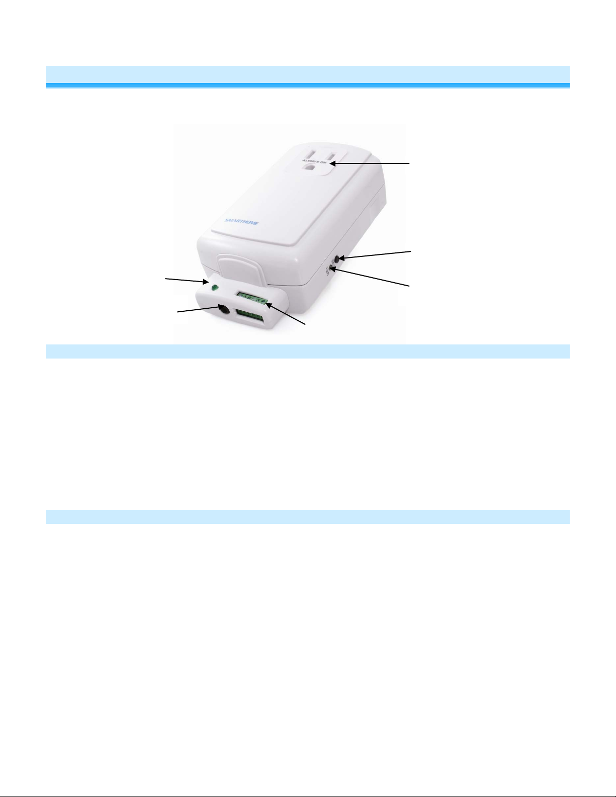
Sensor
Sensor input
3.5mm jack
Screw
terminals
Status LED
Set button
Pass-through outlet
About I/O Linc
I/O Linc allows you to monitor and control an y low volt age de vice ( such as al arm sensor, e lectric door s trik e, etc .) as
part of your INSTEON home automation networ k. With one dr y-contac t sensor inp ut you can c ontrol m an y INST EON
devices throughout the h ouse. Plus, use the built -in single-pole double-t hrow (SPDT) switch to con nect to any lowvoltage-powered device for continuous or momentary operation.
Status LED
Key I/O Linc Features
• Installs and links to other INSTEON devices in minutes
• Contains 1 sensor input and 1 output relay (NO/NC)
• Monitors and contro ls pool valves, electric door s trikes, garage doors, a nd more using your INSTEON or X 10
network
• 4 output relay modes allow you to control many different types of devices
• Controls INSTEON lights and appliances using standard sensor
• Indicates INSTEON setup mode activity with a Status LED and be eper
• Two-year warranty
What is Included with I/O Linc
• I/O Linc – INSTEON Low Voltage / Contact Closure Interface
• 1.5mm flathead screwdriver
• Quick-Start Guide
Page 3 of 16
Page 4

5V
GND
S
N/C
N/O
COM
5 Volt
Ground
Sense
Normally
Normally Open
Common
Installation
Tools You Will Need
• Sensor wire: 16 – 28 gauge wire fits but 20 – 22 gauge is recommended
Preparing to Install I/O Linc
CAUTION
Read and understand these instructions before installing and retain them for future reference.
I/O Linc is intended for inst allation in accor dance with the Nat ional Electric Cod e and local reg ulations in the United
States or the Canadia n Electrical Code and local regulations in Canada. Use indoor s only. I/O Linc is not designed
nor approved for use on power lines other tha n 120V 60H z. Attem pting to use I/O Linc on non-approved power lines
may have hazardous consequences.
Prior to installing I/O Linc, please review the entire installation procedure and take the following precautions:
• Use indoors or in a properly insulated and weatherproof electrical box only
• Don’t plug I/O Linc into an outlet controlled by a switc h because if the switch is i nadvertently turned off , I/O
Linc won’t have power
• Don’t plug I/O Linc into a filtered power strip or AC filter
• Don’t stack INST EON home aut om ation devices toget her b y pluggin g them into e ach oth er. Stac k ed devices
may overheat and stop f unct ioning. Also av oid us ing the pas s-t hrough o utlets on INST EON de vices f or other
heat-generating power supplies.
• Don’t use I/O Linc to control devices tha t preserve, maintain, or cont ribute to human or animal safet y or life
support
• If you are using I/O Linc to control a gara ge door, you shou ld only remotely close a g arage door when you
can be sure it is s afe. Use of safety beam devices can further increase the safet y of remote garage door
control and are usually required by law. Smarthome is not responsible for any damage from proper or
improper functioning of the device(s).
If you have any questions, please call:
INSTEON Support Line
866-243-8022
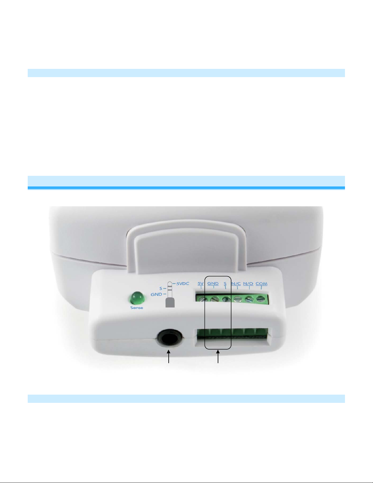
I/O Linc Screw Terminals
Terminals:
• 5 Volt – Provides 5 Volts @ 10mA (if needed)
• Ground – Used with Sense terminal for detecting sensor status
• Sense – Used with Ground terminal for detecting sensor status
NOTE: Applying more than 5 Volts can damage the I/O Linc sensor input.
• Normally Closed – When the I/O Linc output relay is closed, its Normally Closed and Common terminals are
Closed
connected
Page 4 of 16
Page 5
3.5mm
Sensor Screw
• Normally Open – When the I/O Linc outp ut relay is open, its Normally Open and Comm on terminals are
connected
• Common – When the I/O Linc output relay opens and closes, its Common termina l will alternate between
being connected to its Normally Open and Normally Closed terminals
Installing I/O Linc
1) Plug I/O Linc into an unswitched outlet near your sensor
The white I/O Linc Status LED will turn on
2) If using a sensor, connect one of its leads to the I/O Linc Ground terminal and the other to the Sense terminal
The green Sensor Status LED will turn on and off when you open and close the sensor
3) If you are planning to use t he I/O Linc output re lay, it is recomm ended to wait until af ter setting up the I/O Linc
output relay before connecting it. Se e I/O Linc Output Relay Modes.
Setting Up the I/O Linc Sensor Input
You can connect a sensor to the I/O Linc either using the screw terminals or a sensor that utilizes a 3.5mm connection.
Linking the I/O Linc Sensor Input to an INSTEON Responder
Any device that is Linked to I/O Linc (the load) using these instructions will be controlled when:
Sensor
Input
• The I/O Linc connected to the sensor is either opened or closed
• The I/O Linc Set button is tapped
Page 5 of 16
Terminals
Page 6

2477D
NOTE: During linking, you will have the option to turn on remote INSTEON devices when either the connected sensor is closed or
when it is opened. Once this is programmed, the opposite action will trigger an OFF command. For example, if you program an
ON command to be sent when the I/O Linc connected sensor is closed, opening the sensor will trigger an OFF command.
1) Put your sensor into the state you want to use to trigger I/O Linc to send an ON command. For example, if you want closing
the sensor to send an ON command, close the sensor.
The Sensor Status LED
2) Set I/O Linc to linking mode by pressing & holding the Set button until it beeps (3 seconds)
The I/O Linc Status LED
You will have 4 minutes to complete the next step before linking mode automatically times out.
3) Press & hold the Responder’s Set button for 3 seconds
The I/O Linc Status LED
4) Confirm that linking was successful by tapping the Set button on I/O Linc
The responder
will respond appropriately
will turn on if the sensor is closed and off if the sensor is open
will begin blinking
will stop blinking and turn on solid
Unlinking an INSTEON Responder from I/O Linc
1) If the responder is a multi-scene device, tap the Scene button you wish to remove control from until its LED
illuminates
2) Set I/O Linc to linking mode by pressing & holding the Set button until it beeps ( 3 seconds)
The I/O Linc Status LED will begin blinking
3) Set I/O Linc to unlinking mode by pressing & holding the Set button until it beeps again (3 seconds)
The I/O Linc Status LED will continue blinking
You will have 4 minutes to complete the next step before unlinking mode automaticall y tim es out.
Page 6 of 16
Page 7

4) Press & hold the Responder’s Set button for 3 seconds
The I/O Linc Status LED will stop blinking and turn on solid
5) Confirm that unlinking was successful by tapping the Set button on I/O Linc
The responder will no longer respond
Triggering the I/O Linc Output Relay from its Sensor Input
To enable / disable this feature, follow these instructions. This feature is disabled by default.
1) Set I/O Linc to linking mode b y pressing & holding the Set button until it beeps (3 seconds)
The I/O Linc Status LED will begin blinking
2) Triple-tap the Set button on I/O Linc to enable/disable the output relay from its sensor input
I/O Linc will beep and its Status LED will turn on solid
NOTE: Regardless of whether the I/O Linc s ensor in put is progr amm ed to s end an ON com m and when th e sens or is
closed and an OFF command when the sensor is opened, or vice versa, the output relay will:
• Close when an INSTEON ON command is sent (as a result of a sensor)
• Open when an INSTEON OFF command is sent (as a result of a sensor)
Setting Up The I/O Linc Output Relay
I/O Linc Output Relay Modes
Once you’ve completed installation, choose which output relay mode best suits your application and proceed to
Linking an INSTEON Controller to Control the I/O Linc Output Relay.
Latching (Continuous)
When the relay is either opened or closed, it will remain in that state until it is triggered. This is the factory default setting.
An ON command can be programmed to either open or close the relay; an OFF command will do the opposite. For
example, if the relay is programmed to open in response to an ON command, an OFF command will close the relay.
Page 7 of 16
Page 8

In this example, a KeypadLinc is programmed to control sprinklers. When KeypadLinc sends an ON command, I/O Linc will
close the relay, turning on the sprinklers. They will remain on until KeypadLinc s ends an OFF command, opening the I/O
Linc relay and turning off the sprinklers.
NOTE ABOUT MOMENTARY MODES: The relay will remain open until triggered. Once triggered, the relay will
remain closed for t he momentary duration (defau lt: 2 seconds) and th en it will automatically open. T o change the
momentary duration, see
Momentary A
Either an ON or OFF command can be programmed to trigger the I/O Linc relay. Th e other command will be ignored. For
example, if an ON command is programmed to trigger the relay, an OFF command will be ignored.
Setting the I/O Linc Momentary Duration.
In this example, a Mini Remote “Movie Time” scene is set to control two I/O Lincs which each control a direction for the
projection screen. When the scene is activated (on), the lights go to the ideal movie-watching brightness, the projector is
powered on, the Blu-ray player is set to play, and the projection screen is lowered.
Once the movie is over the scene is deactivated (off), so the lights fade off, etc. and the projection screen is raised. This
scene is made possible because the first I/O Linc (DOWN) is programmed only to respond to “Movie Time” ON, while the
second I/O Linc (UP) is programmed only to respond to “Movie Time” OFF.
NOTE: W hen c ontrolling the projectio n screen in this m anner, you will likel y need to extend the I/O L inc momentary
duration. See
Setting the I/O Linc Momentary Duration.
Momentary B
Send either an ON or an OFF command to trigger the I/O Linc relay. The I/O Linc relay will respond to both.
Page 8 of 16
Page 9

In this example, a Mini Remote is used to control an I/O Linc connected to a door strike. For convenience,
Momentary B is used here because pres sing either on or off on Mini Rem ote’s “ U nlock F ront Do or” sc ene wil l unlock
the door.
Momentary C
Use the I/O Linc sensor input to deter mine whether the I/O Linc relay will trigg er. An ON command’s desired state
can be programmed to either open or closed. I/O Linc will use the op posite for the OFF co mmand’s desired sensor
state. For example, if an ON command is pr ogramm ed to trigger on ly when the sensor is cl osed, an OF F comm and
will trigger only when the sensor is open.
In this example, a KeypadLinc scene cont rols the garage door. With I/O Linc in Momentar y C mode and wired to a
sensor and the garage doo r motor like above, the KeypadL inc now has specific On/Off (Open/Close) control of the
garage door. For exam ple, if I/O Linc recei ves an O N c omm and from the Keypad Linc a nd the g arage door is alr ead y
open, I/O Linc will ignor e the comm and and leave the gar age door open. Ho wever, if an OF F command is rec eived,
I/O Linc will close the garage.
Note: If you are using I/O Linc to c ontro l a garage door, a qu ick s tart guide specif ical ly for this f unction can be found
at http://www.insteon.com/support
CAUTION: You should only remotely close a garage door when you can be sure it is safe, either by watching it
directly or through a camera.
Once you have chosen the desired output relay m ode, pr oceed to linking and follow the instructions for the mode you
have chosen. See Linking an INSTEON Controller to Control the I/O Linc Output Relay.
.
Linking an INSTEON Controller to Control the I/O Linc Output Relay
NOTE: The following s teps assume the I/O L inc output relay is sti ll set to the factor y default Latching (Continu ous)
Mode. If this is not the case, either s et the I/O Linc output relay mode back to Latching (see Setting the I/O Linc
Output Relay Mode) or r estore I/O Linc to its factor y default settings (see Reset ting I/O Linc to its Factory Default
Settings).
Page 9 of 16
Page 10

Once you have selec ted th e des ired outp ut re la y mode, f ind it belo w and follow the ins tructio ns to Link I/O Linc to a n
INSTEON Controller.
Latching (Continuous)
1) Tap the Set button on I/O Linc to set the relay to the desired s tate. For exam ple, if you want an ON comm and to
open the relay, se t the relay to be open. If you want an ON command to close the relay, set the relay to be
closed.
The I/O Linc Status LED will be dim if the relay is open or bright if the relay is closed
2) Set the controller to linking Mode. (For most Control lers, press & hold an On or Scene butto n for 10 seconds or
the Set button for 3 seconds.)
You will have 4 minutes to complete the next step before linking mode automatically times out.
3) Press & hold the Set button on I/O Linc until it beeps (3 seconds)
4) Confirm that linking was successful by tapping the button you just Linked to on the Controller
The I/O Linc relay will open and close
Now that setup is complete, it is safe to connect your device to the I/O Linc output relay.
Momentary A
1) By tapping the Set button on I/O Linc, s et the relay to either open (if you want the relay to trigger fr om an OFF
command) or closed (if you want the relay to trigger from an ON command)
The I/O Linc Status LED will be dim if the relay is open or bright if the relay is closed
2) Set the controller to linking Mode. (For mos t Controllers, press & hold an On or Scene button for 10 sec onds or
the Set button for 3 seconds.)
You will have 4 minutes to complete the next step before linking mode automatically times out.
3) Press & hold the Set button on I/O Linc until it beeps (3 seconds)
4) Repeat steps 1-3 for each controller you want to use to control I/O Linc. Once you have Linked all of the
Controllers to I/O Linc, proceed to Setting the I/O Linc Output Relay Mode and follow the instructions for
Momentary A.
Momentary B
1) Set the controller to linking Mode. (For mos t Controllers, press & hold an On or Scene butto n for 10 seconds or
the Set button for 3 seconds.)
You will have 4 minutes to complete the next step before linking mode automatically times out.
2) Press & hold the Set button on I/O Linc until it beeps (3 seconds)
3) Proceed to Setting the I/O Linc Output Relay Mode and follow instructions for Momentary B
Momentary C
1) Set the sensor to the desired on state (m eaning an ON command will not trigger the I/O Linc relay when the
sensor is in this state). For example, if you want an ON command to open the garage door and an OFF
command to close it, open the garage door in this step.
The Sensor Status LED will turn on if the sensor is closed and off if the sensor is open
2) Set the controller to linking Mode. (For most Control lers, pr ess an On or Scene button for 10 sec onds or th e Set
button for 3 seconds.)
You will have 4 minutes to complete the next step before linking mode automatically times out.
3) Press & hold the Set button on I/O Linc until it beeps (3 seconds)
4) Proceed to Setting the I/O Linc Output Relay Mode and follow instructions for Momentary C
Setting the I/O Linc Output Relay Mode
Once you have completed linking, follows the instructions below to change the I/O Linc output relay mode. By default, I/O
Linc is set to Latching (Continuous).
1) Set I/O Linc to linking mode by pressing & holding the Set button until it beeps (3 seconds)
The I/O Linc Status LED
2) Set I/O Linc to unlinking mode by pressing & holding the Set button until it beeps again (3 seconds)
The I/O Linc Status LED
will begin blinking
will continue blinking
Page 10 of 16
Page 11

3) Set I/O Linc to Output Relay Programming mode by pressing & holding the Set button until it beeps a third time (3
seconds)
The I/O Linc Status LED
I/O Linc
Momentary B
4) If you wish to rotate I/O Linc to the next Output Relay Programming mode in the cycle, repeat steps 1-3
will rotate to the next Output Relay Programming mode in the cycle: Latching
→
Momentary C
will stop blinking and turn on solid
→
Momentary A →
Setting the I/O Linc Momentary Duration
To change the amount of time the I/O Linc output relay is closed when it is in one of the momentary modes (A-C), follow
these instructions. By default, the momentary duration is 2 seconds.
For Rev 1.1 and above
NOTE: Momentary duration can be set manually anywhere from 2 seconds up to 24 seconds or for 30 minutes.
1) Set I/O Linc to linking mode by pressing & holding the Set button until it beeps (3 seconds)
The I/O Linc Status LED
2) Set I/O Linc to unlinking mode by pressing & holding the Set button until it beeps again (3 seconds)
The I/O Linc Status LED
3) Tap the Set button on I/O Linc
I/O Linc
4) Press & hold the Set button on I/O Linc for the desired amount of time for its relay to be closed (when in a momentary
mode) and then release
To set the momentary duration for 30 minutes, press & hold the Set button for any amount of time longer than 25
seconds.
5) Tap the Set button on I/O Linc to exit the programming mode
I/O Linc
For Rev 1.0 and below
NOTE: The momentary duration can be set manually anywhere from 2 seconds up to 25 seconds. Or you can use
INSTEON home automation software (such as HouseLinc) to set the momentary duration anywhere from 0.2 seconds up to
25 seconds.
1) Set I/O Linc to linking mode by pressing & holding the Set button until it beeps (3 seconds)
The I/O Linc Status LED
2) Set I/O Linc to unlinking mode by pressing & holding the Set button until it beeps again (3 seconds)
The I/O Linc Status LED
3) Tap the Set button on I/O Linc
I/O Linc
4) Press & hold the Set button on I/O Linc for the desired amount of time for its relay to be closed (when in a momentary
mode) and then release
The I/O Linc Status LED
5) Tap the Set button on I/O Linc to exit the programming mode
I/O Linc
will beep and its Status LED will continue blinking
will beep and its Status LED will stop blinking and turn on solid
will beep and its Status LED will continue blinking
will beep and its Status LED will stop blinking and turn on solid
will begin blinking
will continue blinking
will begin blinking
will continue blinking
will continue blinking
Unlinking I/O Linc from an INSTEON Controller
If you are going to discontinue using I/O Linc, it is very important that you unlink it from any linked controllers.
Otherwise, the controller will retry any commands repetitively, thus slowing down the system.
The following will work for the most common INSTEON devices:
1) Set the controller to unlinking Mode. (F or most Controllers, press & ho ld an On or Scene button for 10 seco nds
twice or the Set button for 3 seconds twice.)
2) Press & hold the Set button on I/O Linc until it beeps (3 seconds)
The I/O Linc Status LED will turn off for about 1 second and then turn back on
Page 11 of 16
Page 12

3) Confirm that unlinking was successful by tapping the button you just Unlinked from on the controller
I/O Linc will no longer respond
Creating An INSTEON Scene
INSTEON scenes let you activ ate dramatic lighting moods with the press of just one button. For exam ple, you can
set all the lights in a scene t o dim to 50% or turn certain l ights on w hile turn ing others off, all with the ta p of a but ton
on a Controller.
INSTEON scenes are ver y easy to set up – just Link m ore than one responder to the same On/O ff or Scene button
on a Controller. Then, when you press any of the Linked buttons on the Controller, all of the INSTEON devices
Linked in the scene will respond as a group.
To set up an INSTEON scene, you can individually Link each device to a Controller.
Advanced Features
Restoring Power to I/O Linc
I/O Linc stores all of its settings, such as Links to other INSTEON devices, with non-volatile memory. Because
settings are saved in this non-volatile memory, they will not be lost in the event of a power failure.
Resetting I/O Linc to its Factory Default Settings
The factory reset proced ure will clear the I/O Linc memory and restore its f actor y default s ettin gs. T his proc edure wil l
result in the following:
• All INSTEON Links will be cleared
• X10 addresses will be reset (none by default)
• Sensor input’s control of output relay will be reset to disabled
• Output relay mode will be reset to Latching
• Momentary duration will be reset to 2 seconds
1) Before resetting an I/O Linc that has been Linked to an INSTEON Controller, be sure to Unlink it from the
Controller. See Unlinking I/O Linc from an INSTEON Controller.
2) Unplug I/O Linc for about 10 seconds
3) While holding down the Set button, plu g I/O Linc back in, making sure not to let go of the Set button
4) Continue to hold down the Set button for 3 seconds
The I/O Linc Status LED will flash once and then turn off for a fe w seconds. I/O Linc will beep as its Status
LED turns back on.
X10 Programming Options
I/O Linc is X10 ready, meaning that it can respond to X10 commands from X10 controllers and it can send X10
commands to X10 devices. However, as it ships from the factory or after a factory reset, I/O Linc will not have an X10
address set up.
Assigning an X10 Address to the I/O Linc Sensor Input
1) Set I/O Linc to linking mode by pressing & holding the Set button until it beeps (3 seconds)
The I/O Linc Status LED will begin blinking
2) Tap the Set button on I/O Linc
I/O Linc will beep and its Status LED will continue blinking
Page 12 of 16
Page 13

Problem
Possible Cause
Solution
The Status LED on I/O
at all.
The controller or
unlinking I/O Linc from it.
3) Using an X10 controller, send either ON (for I/O Linc to send an X10 ON command when the sensor closes and an
X10 OFF command when the sensor opens) or OFF (for I/O Linc to send an X10 ON command when the sensor
opens and an X10 OFF command when the sensor closes)
I/O Linc will beep and its Status LED will stop blinking and turn on solid
Removing an I/O Linc X10 Address from its Sensor Input
1) Set I/O Linc to linking mode by pressing & holding the Set button until it beeps (3 seconds)
The I/O Linc Status LED will begin blinking
2) Set I/O Linc to unlinking mode by pressing & holding the Set button until it beeps again (3 seconds)
The I/O Linc Status LED will continue blinking
3) Tap the Set button on I/O Linc
I/O Linc will beep and its Status LED will continue blinking
4) Using an X10 controller, send the X10 address you want to remove followed by the OFF command three times.
For example, A1 OFF A1 OFF A1 OFF.
I/O Linc will beep and its Status LED will stop blinking and turn on solid
Assigning an X10 Address to the I/O Linc Output Relay
1) Set I/O Linc to linking mode by pressing & holding the Set button until it beeps (3 seconds)
The I/O Linc Status LED will begin blinking
2) Using an X10 controller, send the desired X10 address three times.
For example, A1 A1 A1.
3) From the X10 controller, send either ON (to close the I/O Linc output relay with an X10 ON command and open its
relay with an X10 OFF command) or OFF (to open the I/O Linc output relay with an X10 ON command and close its
relay with an X10 OFF command)
I/O Linc will beep and its Status LED will stop blinking and turn on solid
4) Press & hold the Set button on I/O Linc until it beeps (3 seconds)
The Status LED will begin blinking
Removing an I/O Linc X10 Address from its Output Relay
1) Set I/O Linc to linking mode by pressing & holding the Set button until it beeps (3 seconds)
The I/O Linc Status LED will begin blinking
2) Set I/O Linc to unlinking mode by pressing & holding the Set button until it beeps again (3 seconds)
The I/O Linc Status LED will continue blinking
3) Using an X10 controller, send the X10 address you want to remove and the OFF command three times.
For example, A1 OFF, A1 OFF, A1 OFF.
I/O Linc will beep and its Status LED will stop blinking and turn on solid
Troubleshooting
Linc is not turning on
I/O Linc won’t link or
work with a controller
or Responder.
I/O Linc may not be
getting power.
responder might have
been reset without
Make sure that I/O Linc is not plugged into a
switched outlet that is turned off.
Re-Link I/O Linc to the controller or Responder.
Page 13 of 16
Page 14

Problem
Possible Cause
Solution
The controller or
line phases.
Add additional INSTEON devices or move around
act as INSTEON network repeaters.
Large appliances, such as
on the power line.
Other electrical devices,
the INSTEON signal.
The controller m a y be
loading down the signal.
If the above doesn’t work, perform a factory reset
on the Controller.
Unlink any unused responders from I/O Linc.
eliminate unnecessary Links.
If the above doesn’t work, perform a factory reset.
Settings.
General
Brand:
INSTEON
Manufacturer Product No.:
2450, I/O Linc
UPC:
689076403542
Color:
White
Warranty:
2 years, limited
Operation
Status LED:
White (Bright when relay closed, dim when relay open)
I/O Linc is taking a
long time to respond
to a Controller.
responder and I/O Linc
may be on opposite power
The INSTEON signal may
be too weak.
refrigerators or air
conditioners, may be
producing electrical noise
such as computers,
televisions, or power
strips, may be absorbing
sending commands to a
responder that is no
longer in use. Commands
for the unused responder
are being resent and
Make sure two dual-band INSTEON devices ar e
properly installed to bridge the two power line
phases.
existing INSTEON devices. All INSTEON devices
Install a power line noise filter (#1626-10) to filter
electrical noise and minimize signal attenuation.
Unlink any unused responders from the Controller.
HINT: If you are using home automation software,
you can easily check scene membership and
eliminate unnecessary links.
I/O Linc may be sending
commands to a responder
Responders are taking
a long time to respond
to I/O Linc.
I/O Linc is locked up.
If you have tried these solutions, reviewed this Owner’s Manual, an d s ti ll cann ot resolve an issue you are ha ving with
I/O Linc, please call: 866-243-8022
that is no longer in use.
Commands for the unused
responder are being
resent and loading down
the signal.
A surge or excessive
noise on the power line
may have glitched it.
HINT: If you are using home automation software,
you can easily check scene membership and
If the above doesn’t work, perform a factory. See
Resetting I/O Linc to its Factory Default Settings.
Unplug I/O Linc for 10 seconds and then reinstall.
See Resetting I/O Linc to its Factory Default
Specifications
Page 14 of 16
Page 15

Sensor Status LED:
Green (On when sensor closed, Off when sensor open)
Set Button:
Toggles output relay On/Off. Also used for setup.
Momentary Duration:
Adjustable, 2 - 105 minutes
Operation Modes:
INSTEON only, X10 only, INSTEON and X10 Combo Mode
Combo mode Message Order:
INSTEON, INSTEON confirmation, X10
Multi-Way Circuit Support:
Yes
Setup Memory:
Non-volatile EEPROM
INSTEON Features
INSTEON Addresses:
1 hard-coded out of 16,777,216 pos sib le
INSTEON Links:
417
INSTEON Powerline Frequency:
131.65 KHz
INSTEON Minimum Transmit Level:
3.2 Vpp into 5 Ohms
INSTEON Minimum Receive Level:
10 mV
INSTEON Messages Repeated:
Yes
Mechanical
I/O Terminals:
5V (10mA), GND, Sense, N/C, N/O, Common (28-16 gauge wire)
Input jack:
1/8" mini jack input (GND, Sense)
Input Type:
Contact closure only
Output Relay Capacity:
5A @ 30 Volts (AC or DC)
Operating Conditions:
Indoors, 32 to 104°, up to 85% relative humidity
Dimensions:
4.5" H x 2.5" W x 1.5" D
Weight:
4.6 oz
Electrical
Supply Voltage:
120 Volts AC +/- 10%, 60 Hertz, single phase
Sensor Input:
1/8" mini jack input (GND, Sense)
Power Plug :
3-pin grounded
Pass-through Outlet:
Uncontrolled 3-prong (with ground), 120V, 15A
Power Consumption:
0.93 Watts
Certification:
Safety tested for use in USA and Canada
X10 Features
X10 Primary Address:
Two optional (comes unassigned). One for input, one for output
Certification And Warr a nty
Certification
This product has been thoroughly tested by ITS ETL SEMKO, a nationally recognized independent third-party testing laboratory. The North American ETL Listed mark
signifies that the device has been tested to and has met the requirements of a widely recognized consensus of U.S. and Canadian device safet y stand ar ds, t hat the
manufacturing site has been audited, and that the manufacturer has agreed to a program of quart erly factory follow-up inspections to verify continued conformance.
Limited Warranty
Seller warrants to the original consumer purchaser of this product that, for a period of two years from the date of purchase, this product will be free from def ects in
material and workmanship and will perform in substantial conformity to the description of the product in this Owner’s Manual. This warranty shall not apply to defects or
Page 15 of 16
Page 16

errors caused by misuse or neglect. If the product is found to be defective in material or workmanship, or if th e pro duc t does not pe rfo rm as warranted above during the
warranty period, Seller will either repair it, replace it, or refund the purchase price, at its option, upon receipt of the product at the address below, postage prepaid, with
proof of the date of purchase and an explanation of the defect or error. The repair, replacement, or refund that is provided for above shall be the full extent of Seller’s
liability with respect to this product. For repair or replacement during the warranty period, call the INSTEON Support Line at 866-243-8022 with the Model # and
Revision # of the device to receive RMA # and send the product, along with all other required materials to:
INSTEON
ATTN: Receiving Dept.
16542 Millikan Ave.
Irvine, CA 92606-5027
Limitations
The above warranty is in lieu of and Seller disclaims all other warranties, whether oral or written, express or implied, including any warranty or merchantability or fitness
for a particular purpose. Any implied warranty, including any warranty of merchantability or fitness for a particular purpose, which may not be disclaimed or supplanted
as provided above shall be limited to the two-year of the express warranty above. No other representation or claim of any nature by any person shall be binding upon
Seller or modify the terms of the above warranty and disclaimer.
Home automation devices have the risk of failure to operate, incorrect operation, or electrical or mechanical tampering. For optimal use, manually verify the device
state. Any home automation device should be viewed as a convenience, but not as a sole method for controlling your home.
In no event shall Seller be liable for special, incidental, consequential, or other damages resulting from possession or use of this device, including without limitation
damage to property and, to the extent permitted by law, personal injury, even if Seller knew or should have known of the possibility of such damages. Some states do
not allow limitations on how long an implied warranty lasts and/or the exclusion or limitation of damages, in which case the above limitations and/or exclusions may not
apply to you. You may also have other legal rights that may vary from state to state.
Protected under U.S. and foreign patents (see www.insteon.com)
© Copyright 2013 INSTEON, 16542 Millikan Ave., Irvine, CA 92606, 866-243-8022, www.insteon.com
Page 16 of 16
 Loading...