

Page 1

Micro On/Off
North America
EU/AUS/NZ
Owner’s Manual
2443-222 (US)
2443-422 (EU)
2443-522 (AUS/NZ)
Page 1 of 21 2443-222/2443-422/2443-522 - Rev: 1/21/2014 8:28 AM
Page 2

About Micro On/Off ..................................................................................................................................... 3
Features and Benefits ............................................................................................................................... 3
Before Installation ....................................................................................................................................... 3
Identifying the Electrical Wires in Your Home (North America only) ......................................................... 4
Identifying the Electrical Wires in Your Home (Europe/Australia/New Zealand) ....................................... 4
Identify Switch Type .................................................................................................................................. 4
Installation ................................................................................................................................................... 5
Switch Operation Mode .............................................................................................................................. 6
Change to Single Momentary Mode .......................................................................................................... 6
Change to Dual Momentary Mode ............................................................................................................ 6
Change to Latching Mode (default) ........................................................................................................... 6
3-Way Toggle Mode (Latching Switches Only, Default) .......................................................................... 7
Local Control Operation ............................................................................................................................. 7
Latching Wall Switch (Default) .................................................................................................................. 7
Single Momentary Switch .......................................................................................................................... 8
Dual Momentary Switch ............................................................................................................................. 8
Adjust Local Settings ................................................................................................................................. 8
Change LED Brightness (or turn it off) ...................................................................................................... 8
Error Blink .................................................................................................................................................. 8
Blink on Traffic ........................................................................................................................................... 9
Beep on Button Press ................................................................................................................................ 9
Programming Lock .................................................................................................................................... 9
INSTEON Setup ........................................................................................................................................... 9
INSTEON Controllers, Responders and Links .......................................................................................... 9
Configure INSTEON Settings .................................................................................................................... 9
Make Micro Module a Responder (Set button).......................................................................................... 9
Make Micro Module a Responder (Switc h) ............................................................................................. 10
Make Micro Module a Controller (Set butt on).......................................................................................... 10
Make Micro Module a Controller (Swit ch) ............................................................................................... 10
Groups ..................................................................................................................................................... 11
Scenes ..................................................................................................................................................... 11
Make Micro Module a Controller of Multip le Res po nder s ....................................................................... 11
Remove Micro Module as a Controller .................................................................................................... 12
Remove Micro Module as a Responder .................................................................................................. 12
Remove Micro Module as a Controller of Multiple Responders .............................................................. 12
Factory Reset .......................................................................................................................................... 12
X10 Setup ................................................................................................................................................... 13
Add X10 Address ..................................................................................................................................... 13
Remove X10 Address .............................................................................................................................. 13
Specifications ............................................................................................................................................ 14
Troubleshooting ........................................................................................................................................ 17
Stuck/Disabled Button ............................................................................................................................. 18
Phase Bridge Detect Beacon/RF Range Test ......................................................................................... 19
Certification and Warranty ....................................................................................................................... 20
Certification .............................................................................................................................................. 20
FCC and Industry Canada Compliance Statement ................................................................................. 20
Declaration of Conformity ........................................................................................................................ 20
ETL/UL Warning (Safety Warning) .......................................................................................................... 20
Limited Warranty ..................................................................................................................................... 20
Limitations................................................................................................................................................ 21
Page 2 of 21 2443-222/2443-422/2443-522 - Rev: 1/21/2014 8:28 AM
Page 3
In the Box
Tools Needed
Optional Accessories
Micro On/Off
Slotted screwdriver
Mini Remote
Quick Start Guide
Phillips screwdriver
INSTEON Hub
Wire cutter/stripper
Voltage meter
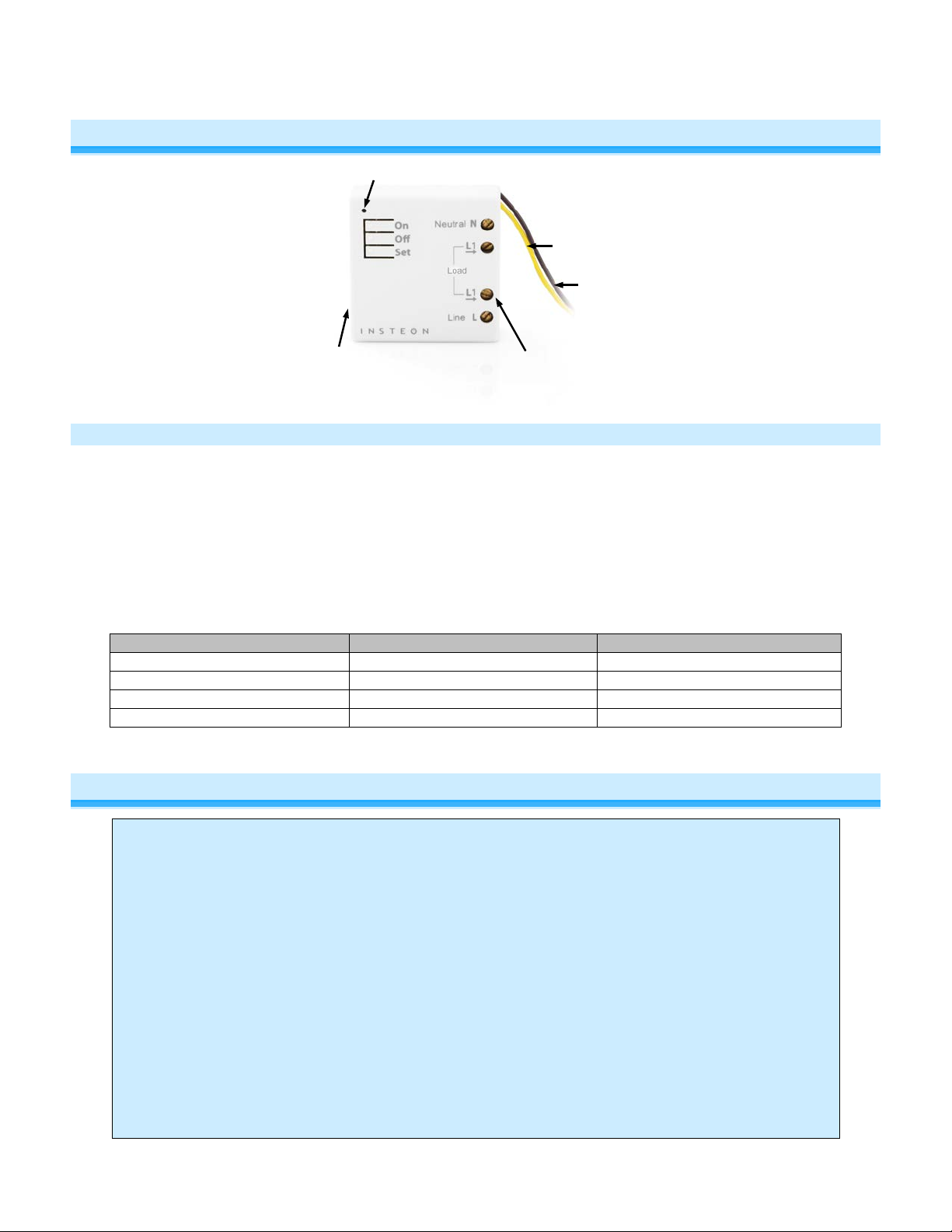
DIMMING AN INDUCTIVE LOAD.
Sense #1
(yellow)
Sense #2
LED
Antenna
Second Load Terminal
optional based on region
About Micro On/Off
(purple)
Features and Benefits
- Wires in behind existing wall switch or outlet or in a fixture box (requires neutral wire)
- Compatible with latching, single momentary and dual momentary switches
- Sense wires allow local control from any standard wall switch
- Can contain up to 400 controller/responder links
- X10 compatible
- All settings preserved in non-volatile memory, even through power failures
- Beeper for easy setup assistance; can also function as a chime module
- Local programming lockout available via software
- 2-year warranty
Before Installation
CAUTIONS AND WARNINGS
Read and understand these instructions before installing and retain them for future reference.
This product is intended for installation in accordance with the National Electric Code and local regulations in the United States or
the Canadian Electrical Code and local regulations in Canada. Use indoors only.
This product is not designed or approved for use on power lines other than 100-240VAC,50Hz or 60Hz, single phase. Attempting
to use this product on non-approved power lines may have hazardous consequences.
- Use only indoors or in outdoor rated box
- Be sure that you have turned off the circuit breaker or removed the fuse for the circuit you are installing this product into.
Installing this product with the power on will expose you to dangerous voltages.
- Connect using only copper or copper-clad wire
- This product may feel warm during operation. The amount of heat generated is within approved limits and poses no
hazards. To minimize heat buildup, ensure the area surrounding this product is as clear of clutter as possible.
- Each INSTEON product is assigned a unique INSTEON I.D., which is printed on the product’s label.
- To reduce the risk of overheating and possible damage to other equipment, do not use this product to control loads in
excess of the specified maximum(s) or, install in locations with electricity specifications which are outside of the product’s
specifications. If this device supports dimming, please note that dimming an inductive load, such as a fan or transformer,
could cause damage to the dimmer, the load bearing device, or both. If the manufacturer of the load device does not
recommend dimming, use a non-dimming INSTEON on/off switch. USER ASSUM ES ALL RISKS ASSO C IATED WITH
Page 3 of 21 2442-222/2442-422/2442-522 - Rev: 1/21/2014 8:28 AM
Page 4

electrical circuitry, you should have a qualified electrician install the product for you.
Identifying the Electrical Wires in Your Home (North America only)
- Line: usually black (may also be called hot, live or power), carries 120VAC electricity into the wall box
- Neutral: usually white or white wire bundle, commonly daisy-chained from box to box
- Load: usually black, from a separate cable jacket
- Ground: bare copper wire or metal fixture (if grounded)
Identifying the Electrical Wires in Your Home (Europe/Australia/New Zealand)
- As wire colors vary from country to country, make sure you always check your electrical wires with a voltage meter to
correctly identify line, load, neutral and ground wires
- If you have any questions, consult an electrician or your electricity supplier to learn more about your country’s wiring colors
and labels
IMPORTANT!
If you have any difficulties or questions, consult an electrician. If you are not knowledgeable about, and comfortable with,
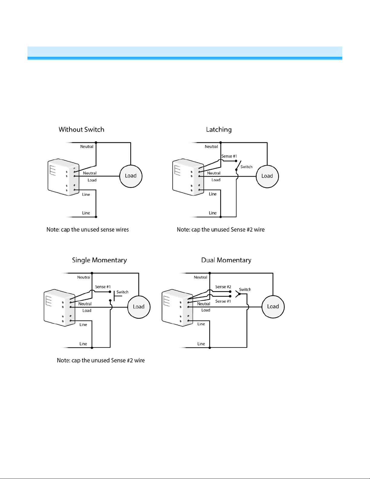
Identify Switch Type
Before you install Micro module behind a switch, you must determine which switch operation mode applies to your
switch—latching, single momentary or dual momentary—as each is wired differently:
• Latching (default mode): Switch has no central position. It can be tapped on both the top and bottom and
remains in that state once released.
• Single momentary: Switch can only be tapped in one location. It returns to central position once released.
• Dual momentary: Switch can be tapped on both the top and bottom. It returns to central position once
released.
Once you have identified your switch type, install Micro module according to the corresponding wiring diagram, then
see “Switch Operation Mode” to program Micro module for your specific switch type.
Note: If you are installing Micro module behind a wall outlet or in a fixture, switch operation mode does not apply.
Page 4 of 21 2443-222/2443-422/2443-522 - Rev: 1/21/2014 8:28 AM
Page 5
Installation
1) Write down the INSTEON ID found on the back of the unit (XX.XX.XX)
2) Turn off breaker/fuse and verify that the power is off
3) Disconnect wires from existing switch, fixture or outlet and prep all wires to
be connected to Micro module, with 3/16” (5mm) of bare wire on the ends
4) Connect wires per diagram which corresponds to your installation
Note: sense lines carry very low current (~0.35mA 240V, ~0.17mA for 120V)
5) After ensuring wires are firmly connected and that there is no exposed wire, turn on breaker/fuse
After a few seconds, load will turn on (if wired into switch or fixture) and Micro module LED will turn green
6) Test by tapping Micro module on/off buttons
Load will turn on and off
Micro Module LED will turn green when load is on and red when load is off
7) If installing a single momentary or dual momentary switch
a) Press and hold set button until it beeps
LED will start blinking green
b) Press and hold set button until it beeps a second time
LED will start blinking red
c) Press and hold set button until it beeps a third time
LED will start blinking green
Page 5 of 21 2443-222/2443-422/2443-522 - Rev: 1/21/2014 8:28 AM
Page 6

d) Perform the step that applies
• For single momentary: slowly tap set button four times
LED will continue blinking green
• For dual momentary: slowly tap set button five times
LED will start double-blinking green
• To switch back to latching: slowly tap set button six times
LED will start blinking green
e) Once the mode is selected, press and hold set button until it doubl e-beeps
LED will stop blinking and t urn green if load is on or red if load is off
Switch Operation Mode
By default, Micro module is programmed for a latching switch. Program the switch operation for single momentary
mode, dual momentary mode or back to latching mode according to your switch type. These settings can also be
configured remotely via software (sold separately).
To determine Micro module’s current switch operation mode, simply tap Set butto n:
• If it beeps, Micro module is configured for a single momentary switch
• If it double-beeps, Micro module is configured for a dual momentary switch
• If it triple-beeps, Micro module is configured for a latching switch (default)
Change to Single Momentary Mode
1) Press and hold Set button until it beeps
LED will start blinking green
2) Press and hold Set button until it beeps again
LED will start blinking red
3) Press and hold Set button until it beeps a third time
LED will start blinking green
4) Slowly tap Set button four times
LED will continue bl inki ng g r een
5) Press and hold Set button until it double-beeps
LED will stop blinking
6) Test mode change by tapping switch on and off
Load will respond appropriately
Change to Dual Momentary Mode
1) Press and hold Set button until it beeps
LED will start blinking green
2) Press and hold Set button until it beeps again
LED will start blinking red
3) Press and hold Set button until it beeps a third time
LED will start blinking green
4) Slowly tap Set button five times
LED will start double-blinking green
5) Press and hold Set button until it double-beeps
LED will stop blinking
6) Test mode change by tapping switch top and bottom
Load will respond appropriately
Change to Latching Mode (default)
1) Press and hold Set button until it beeps
LED will start blinking green
2) Press and hold Set button until it beeps again
LED will start blinking red
Page 6 of 21 2443-222/2443-422/2443-522 - Rev: 1/21/2014 8:28 AM
Page 7

Connected load/responders
Latching switch
Tap
LED
3) Press and hold Set button until it beeps a third time
LED will start blinking green
4) Slowly tap Set button six times
LED will continue bl inki ng g r een
5) Press and hold Set button until it double-beeps
LED will stop blinking
6) Test mode change by tapping switch on and off
Load will respond appropriately
3-Way Toggle Mode (Latching Switches O nly, Default)
Because Micro module comes programmed for latching switches, 3-way toggle mode is enabled by default.
Normally, a latching switch reads the switch’s up position as on and down position as off. For example, if you turn
Micro module on from the latching switch and off from another controller, the switch is still in the up (on) position;
turning Micro module back on from the switch would require you to tap the switch down, then up again.
The 3-way toggle mode overrides this sense feature, so in that same scenario—turning Micro module on at the
switch and off from another controller, so switch is in up (on) position—you could then turn Micro module on at the
switch by tapping it down.
If you are installing Micro module behind a single or dual momentary switch, 3-way toggle mode is ignored. If
desired, you can disable (or re-enable) 3-way toggle mode by following these instructions:
1) Press and hold Set button until it beeps
LED will start blinking green
2) Press and hold Set button until it beeps again
LED will start blinking red
3) Press and hold Set button until it beeps a third time
LED will start blinking green
4) Press and hold Set button until it beeps a fourth time
LED will start blinking red
5) Tap Set button
Micro module will beep and LED will start double-blinking red
6) Press and hold Set button until it double-beeps
LED will stop blinking
3-way toggle mode is now disabled (or re-enabled)
Local Control Operation
Micro module’s switch operation mode affects how it responds to commands from the switch. This is why it’s
important to program Micro module for the specific type of switch you are using. Micro module’s on/off buttons
function exactly like the top and bottom of your wall switch.
Latching Wall Switch (Default)
Note that this table refers to the latching switch operation if 3-way toggle mode is dis ab led (it is enabled b y def ault).
Page 7 of 21 2443-222/2443-422/2443-522 - Rev: 1/21/2014 8:28 AM
Top
Bottom
On
(ramped)
Off
(ramped)
Green
Red
Page 8

Connected load/responders
Single momentary switch
Tap
Press and hold
Double-tap
LED
Connected load/responders
Dual momentary switch
Tap
Press and hold
Double-tap
LED
Single Momentary Switch
Switch
Dual Momentary Switch
Top
Bottom
Adjust Local Settings
On/Off
(ramped)
On
(ramped)
Off
(ramped)
Brighten/Dim
until release or full-on/off
(dimmable responders only)
Brighten
until release or 100%
(dimmable responders only)
Dim
until release or off
(dimmable responders only)
On/Off
(instant)
On
(instant)
Off
(instant)
Green/
Red
Green
Red
Change LED Brightness (or turn it off)
Default = 50% brightness level
1) Press and hold Set button until it beeps
LED will start blinking green
2) Press and hold Set button until it beeps again
LED will start blinking red
3) Press and hold Set button until it beeps a third time
LED will start blinking green
4) Tap Set button once
LED will start double-blinking green
5) Press and hold Set button until it beeps
LED will turn green (at brightness of connected load)
6) Press and hold Micro module on/off buttons to brighten or dim LED to desired brightness
7) Tap Set button
Micro On/Off will double-beep and return to ready mode
Error Blink
Default = enabled
This setting is only adjustable via software or a central controller. Micro module LED will blink red once if one or more
responders do not acknowledge a message and will blink green once if all responders are successful.
Page 8 of 21 2443-222/2443-422/2443-522 - Rev: 1/21/2014 8:28 AM
Page 9

Controller
Responder
Link
Blink on Traffic
Default = disabled
This setting is only adjustable via software or a central controller. Micro module LED will blink red if it detects noise
that could disrupt communication.
Beep on Button Press
Default = disabled
This setting is only adjustable via software or a central controller. Micro module will beep every time its connected
switch is tapped or a button is pressed.
Programming Lock
Default = disabled
This setting is only adjustable via software or a central controller. When enabled, Programming Lock will disable the
Set button so that a user can not adjust settings or modify links. This is typically used in commercial or installer
applications.
INSTEON Setup
Some products have subtle differences in their setup procedures. Please refer to the other devices’ owner’s manuals
for details.
INSTEON Controller s, R es pon der s and Li nk s
• The INSTEON “transmitter” is called a controller
• The INSTEON “receiver” is called a responder
• The association between the controller and responder is called a link
Note that a link is one way. If you wish to have control “the other way,” simply add a link “the other way.”
Configure INSTEON Settings
Most Micro module links and settings can be configured locally—during installation with the module’s Set button or
after installation using the switch connected to the module.
All Micro module settings can be managed remotely via software (sold separately).
Make Micro Module a Responder (Set button)
Note: you must perform these steps before reinstalling the wall switch, outlet or fixture.
1) Press and hold controller Set button until it beeps
Page 9 of 21 2443-222/2443-422/2443-522 - Rev: 1/21/2014 8:28 AM
Page 10

Controller LED will start blinking
You will have four minutes to complete the next steps before linking mode times out
2) Adjust load connected to Micro module to desired brightness level (even off)
3) Press and hold Micro module Set button until it doub le-beeps
Controller will double-beep and its LED will stop blinking
4) Test link by tapping controller button on and off
Load connected to Micro module will respond appropriately
Make Micro Module a Responder (Switch)
1) Press and hold controller Set button until it beeps
Controller LED will start blinking
You will have four minutes to complete the next steps before linking mode times out
2) Adjust load connected to Micro module to desired level (on or off)
3) Quickly tap switch connected to Micro module exactly five times in less than four seconds. (If using a latching or
dual momentary switch, alternate switch directions: up-down-up-down-up or down-up-down-up-down.) After
tapping switch, wait two seconds.
Micro module will double-beep
Controller will double-beep and its LED will stop blinking
4) Test link by tapping controller button on and off
Load connected to Micro module will turn on and off
Make Micro Module a Controller (Set button)
Note: you must perform these steps before reinstalling the wall switch, outlet or fixture.
1) Press and hold Micro module Set button unti l it beeps
Micro module LED will start blinking green
You will have four minutes to complete the next steps before linking mode times out
2) Adjust responder to desired state
1
3) Press and hold responder Set button until it double-beeps
Micro module will double-beep and its LED will stop blinking
2
4) Test link by tapping or pressing and holding Micro module on/off buttons to turn on/off or brighten/dim
Responder will respond appropriately
Make Micro Module a Controller (Switch)
1) Quickly tap switch connected to Micro module exactly five times in less than four seconds. (If using a latching or
dual momentary switch, alternate switch directions: up-down-up-down-up or down-up-down-up-down.) After
tapping switch, wait two seconds.
Micro module will beep to indicate it has entered linking mode
You will have four minutes to complete the next steps before linking mode times out
2) Adjust responder to desired state
3) Press and hold responder Set button until it double-beeps
Micro module wi ll doubl e-beep and its LED will stop blinking
4) Test link by tapping switch connected to Micro module to turn on/off or brighten/dim
Responder will respond appropriately
1
If responder is a multi-scene device such as a KeypadLinc, tap scene button you wish to control until the LED is in the desired scene state (on or off).
2
If either controller or responder LED continues blinking, the addition failed. Tap device’s Set button until LED stops blinking and try linking again.
3
If responder is a multi-scene device such as a KeypadLinc, tap scene button you wish to control until the LED is in the desired scene state (on or off)
3
Page 10 of 21 2443-222/2443-422/2443-522 - Rev: 1/21/2014 8:28 AM
Page 11

Groups
Devices in a group share all the same settings (e.g., on-level, ramp rate). This keeps all group members
synchronized. Every device in a group is both a controller of, and responder to, all the other devices. The most
common example of a group is a 3-way lighting circuit (2 switches). For simplicity, we will assume that the desired
group level is on.
The following steps will create a virtual 3-way circuit including device “A” and device “B”:
1) Turn A and B on
2) Press and hold A Set button until it beeps
A status LED will start blinking green
3) Press and hold B Set button until it double-beeps
A will double-beep and its LED will stop blinking
4) Press and hold B Set button until it beeps
B LED will start blinking green
5) Press and hold A Set button until it double-beeps
B will double-beep and its LED will stop blinking
6) Test by turning load on and off from A and then B
The load(s) and both A and B LEDs will remain in synch
Scenes
Devices in a scene can each have different settings. This provides for advanced scene creation. Software is
recommended for scene management.
Example of a scene with 1 controller and Micro module as a member:
1) Press and hold controller button until it beeps
Controller LED will start blinking green
2) Tap controller Set button
Controller LED will start double-blinking green
3) Adjust load to desired scene state (on or off)
4) Press and hold Micro module Set butt on until it double-beeps
5) For each additional scene member:
a. Adjust member to desired scene state
b. Press and hold Set button until it double-beeps
6) Tap controller Set button
Controller will beep and LED will stop blinking
7) Test by tapping controller button on and off
Micro module and other scene responders will all respond appropriately
Make Micro Module a Controller of Multiple Responders
1) Press and hold Micro module Set butt on until it beeps
LED will start blinking green
2) Tap Micro module Set button
LED will start double-blinking green
3) For each responder you are adding:
a. Adjust responder to desired scene state
b. Press and hold Set button until it double-beeps
4) Tap Micro module Set butt on
Micro module will beep and LED will stop blinking
5) Test by tapping switch wired into Micro module on and off
All the responders will turn on and off
Page 11 of 21 2443-222/2443-422/2443-522 - Rev: 1/21/2014 8:28 AM
Page 12

Remove Micro Module as a Controller
If you no longer want Micro module to control another device (or are removing Micro module from your network) it is
important that you follow the instructions below for each responder.
1) Press and hold Micro module Set butt on until it beeps
LED will start blinking green
2) Press and hold Micro module Set butt on until it beeps again
LED will start blinking red
3) Press and hold responder Set butt on until it double-beeps
Micro module will double-beep and LED will stop blinking
4) Test by tapping Micro module on and off
Former responder will not respond
Remove Micro Module as a Responder
If you no longer want a controller button to control Micro module, follow these directions .
Note: If you ever wish to uninstall Micro module, it is important that you remove all Micro module responder links.
Otherwise, controllers will repetitively retry commands, creating network delays.
1) Press and hold controller button until it beeps
LED will start blinking green
2) Press and hold controller button until it beeps again
LED will start blinking red
3) Press and hold Micro module Set butt on until it double-beeps
Controller LED will stop blinking
4) Test by tapping controller button on and off
Micro module will no longer res pond
Remove Micro Module as a Controller of Multiple Responders
1) Press and hold Micro module Set butt on until it beeps
LED will start blinking green
2) Press and hold Micro module Set button until it beeps again
LED will start blinking red
3) Tap Micro module Set butt on
LED will start double-blinking red
4) For each responder you are removing:
a. Press and hold Set button until it double-beeps
5) Tap Micro module Set butt on
Micro module will be e p and LED will stop blinking
6) Test by tapping the switch wired into Micro module on and off
None of the former responders will respond
Factory Reset
All settings, link s and scenes will be erased.
1) Press and hold Micro module Set butt on until it beeps
LED will start blinking green
2) Press and hold Micro module Set butt on u nt il it beeps aga in
LED will start blinking red
3) Press and hold Micro module Set butt on until it beeps a third time
LED will start blinking green
4) Slowly tap Micro module Set button 3 times
LED will start double-blinking green
5) Press and hold Micro module Set butt on. Do not let go.
Micro module will be g in to emit a long beep
Page 12 of 21 2443-222/2443-422/2443-522 - Rev: 1/21/2014 8:28 AM
Page 13

6) After beep stops, release Micro module Set button
After a few seconds, the LED will flash white
Micro module will double-beep and the load will turn on
X10 Setup
Micro module ships with no X10 address assigned.
Add X10 Address
1) Press and hold Set button until it beeps
LED will start blinking green
2) Send the X10 address 3 times (with or without commands)
Example: A1-AON-A1-AON-A1-AON or A1-A1-A1-AON
Micro module will double-beep and LED will stop blinking
3) Test by sending X10 on and off commands
Load will turn on and off
Remove X10 Address
1) Press and hold Set button until it beeps
LED will start blinking green
2) Press and hold Set button until it beeps again
LED will start blinking red
3) Send the X10 address 3 times (with or without commands)
Example: A1-AOFF-A1-AOFF-A1-AOFF or A1-A1-A1-AOFF
Micro module will double-beep and LED will stop blinking
4) Test by sending X10 on and off commands
Micro module will not respond
Page 13 of 21 2443-222/2443-422/2443-522 - Rev: 1/21/2014 8:28 AM
Page 14

General
Product name
Micro On/Off
Brand/manufacturer
INSTEON
2443-222 (US)
813922012736 (US)
Warranty
2 years, limited
INSTEON
INSTEON
Controller and responder
Maximum links/scenes
400
Green when load is on, red when load is off
Blinks red once when responder does not ac knowledge/blinks green once
Blinks red or green during setup
Blinks to indicate traffic (must be enabled via software)
Beeps when button is pressed or connected switch is tapped (must be
LED brightness
Adjustable, from off to bright
Local control
Yes
On
Off
Fast-on
Fast-off
Begin brighten
Begin dim
End brighten
End dim
On
Off
Fast-on
Fast-off
Beep
Software configurable
Yes
Up to 50 meters (150 feet) open air*
Phase detect beacon
Yes
Specifications
Manufacturer product number
UPC
Status LED
Beep on button press
2443-422 (EU)
2443-522 (AUS/NZ)
813922012743 (EU)
813922012750 (AUS/NZ)
if all responders acknowledge (can be disabled/re-enabled via software)
enabled via software)
Commands supported as controller
Commands Supported as responder
RF range
INSTEON device category
INSTEON device subcategory
Page 14 of 21 2443-222/2443-422/2443-522 - Rev: 1/21/2014 8:28 AM
*Range may vary due to local interference/building construction
0x02 Switched Lighting Control (All Frequencies)
2443-222 (915 MHz)
0x2F
Page 15

X10
X10 address
1 optional (comes unassigned)
X10 transmitter
Yes
X10 receiver
Yes
X10 status response
Supported
X10 resume dim
Supported (by setting local on-level to zero)
X10 minimum transmit level
3.2 Vpp into 5 Ohms
X10 minimum receive level
20mV into 5 Ohms
X10 messages repeated
No
Mechanical
Behind switch or outlet, or above light fixt ure in a single-gang electrical
box
Sense 1 (yellow wire), 0.205mm2 / 24 AWG
Sense 2 (purple wire), 0.205mm2 / 24 AWG
Max Cable Size
Min Cable Size
Screw Micro connections
Line
Load 1
Load 1, second terminal
Neutral
Case Color
White
Set button
Yes
Plastic
UV stabilized ABS+PC
Beeper
Yes
LED
1, RGB
Dimensions
46.6mm H x 46.6mm W x 17.5mm D (1.8” H x 1.8” W x 0.7” D)
Weight
71.5g (2.5 oz)
Operating Environm ent
Indoors
Operating Temperature Range
32°F to 104°F (0°C to 40°C)
Operating Humidity Range
0-90% relative humidity
Storage temperature range
Electrical
Voltage
100VAC to 240VAC
Frequency
50/60Hz auto detected at power-up
15A – 240VAC (US)
Mounting
Wires
2443-422 (869 MHz) 0x31
2443-522 (921 MHz) 0x32
4mm2 (2.72mm diameter) / 12 AWG
1.5mm2 / 15 AWG
-4 o to 158 o F (-20 o to 70 o C)
Maximum load
Page 15 of 21 2443-222/2443-422/2443-522 - Rev: 1/21/2014 8:28 AM
16A – 240VAC (EUR)
10A – 240VAC (AUS/NZ)
Page 16

3600W/240VAC Resistive
Resistive
Hardwired remote control
Yes, latching and momentary switches supported
Retains all settings without power
Yes, saved in non-volatil e EE PR O M
Standby power consumption
< 1 watt
Safety approved
ETL, CE, C-Tick
FCC 15.107, 15.109, 15.249
FCC ID
SBPMM01
700W/240VAC Inductive/Capacitive
2000W/240VAC Bulbs/Low Voltage Halogen
Load type(s)
Inductive/capacitive
Low voltage halogen
RSS 210
EN 300 220-2, 301 489-3
Certifications
AS/NZS 4268, CISPR 22
UL 244A
IEC 60669-2-1
All product specifications are subject to change.
Page 16 of 21 2443-222/2443-422/2443-522 - Rev: 1/21/2014 8:28 AM
Page 17

Problem
Possible Cause
Solution
Make sure the circuit breaker is turned on
Check junction box wires to ensure all
exposed
Check the light fixture to ensure all
exposed
utral
Look in the rear of the junction box for a group
are commonly neutral wires.
The controller is plugged into
a power strip
Powerline signals can’t travel through some
power filters. Plug controller into wall outlet.
Plug other modules into a signal filter or move
the modules or controller to another outlet
INSTEON devices act as network repeaters.
and retest.
Micro module and the
powerline phases
Make sure there are at least 2 dual-band
bridge the phases
Install a power line signal blocker in your home
module in X10 mode.
Micro module may have an
membership
Use software to remove membership or
module
Install an inline signal filter between the load
and Micro module
Micro module may be set up
brightness
Remove the X10 address from Micro module
When I press a button on
controlling to respond
that is not
Connect power to the responder
If the INSTEON device is still available,
remove it from Micro module and then re-add it
Perform a factory reset
Micro module doesn't
Micro module ships with out
Add an X10 address
Troubleshooting
The LEDs on Micro
module are not turning on
at all
The switch I'm replacing
only has two wires
Micro module is not
receiving signals from
INSTEON or X10
controllers
The light turned on by
itself
Micro module is not getting
power
Micro module needs a ne
wire in order to operate
Other modules are
attenuating the signal or
causing noise on the line
controller are on opposite
Another controller, a timer, or
stray X10 signals triggered
Micro module
connections are tight and no bare wires are
connections are tight and no bare wires are
of wires tied together with a wire nut. Those
Pull a neutral from nearby junction box
Add new or move existing INSTEON devices
INSTEON products are properly installed to
to keep X10 signals from neighboring homes
from interfering. Consider not using Micro
undesired responder
load connected to Micro
Micro module responds to
on commands but not off
commands
When I try to turn on my
light with another
controller, the light will
turn on, then back off
Micro module, it takes a
long time for other
INSTEON device s it is
Page 17 of 21 2443-222/2443-422/2443-522 - Rev: 1/21/2014 8:28 AM
module is producing electrical
noise that is interfering with
the Micro module reception of
powerline signal
with an INSTEON on-level at
a high brightness and an X10
address on-level at a low
Micro module is trying to
control a responder
responding and may have
been removed
perform a factory reset and re-setup Micro
Install additional INSTEON devices to boost
the INSTEON signal
Remove the X10 address from INSTEON
controller
Page 18

respond to X10 address
A1 upon install
an X10 Address
Power cycle Micro module
Perform a factory reset
Micro module blinks green
Micro module supports an
communicating properly
Micro module supports an
network
Micro module can turn off
, but nothing
on
half-link)
Micro module is locked up
one time after it is
activated
Micro module blinks red
one time after it is
activated
my responder
happens when I send an
Controller can turn Micro
module off, but not on
A surge or excessive noise
on the power line occurred
error blink feature. A green
blink indicates that all
responders are
error blink to let you know
that a responder did not
acknowledge the command
and that there is a lot of
unacknowledged
communications on the
Responder’s scene level is
off
Micro module may be added
to a scene at its off state
You may disable error blink via software if
desired
Confirm that the responder is powered and
available. If you don’t want this device to be a
responder you can unlink it if available or use
software to remove the link. Once the issue is
resolved, you may disable error blink via
software if desired.
Add responder to scene again at desired
scene on-level
Add Micro module to scene again at desired
scene on-level
Micro module still controls
devices even after factory
reset
The responder’s link was not
removed prior to Micro
module factory reset (called a
Remove responder from Micro module
Stuck/Disabled Button
If Micro module’s buttons are not responding, they may have been disabled due to a stuck button. If any button is
pressed during power-up, or after power-up any Micro module button is pressed for about four minutes, Micro
module engages stuck button mode and automatically disables all button actions. All buttons will remain disabled
until next power cycle.
To re-enable buttons, ensure buttons are not being pressed, turn off breaker supplying power to Micro module and
turn it back on. Micro module buttons should function again. Additionally, check Micro module’s installation location
for any obstacles that could be pressing the buttons on Micro module’s face and causing stuck button mode.
Page 18 of 21 2443-222/2443-422/2443-522 - Rev: 1/21/2014 8:28 AM
Page 19

Phase Bridge Detect Beacon/RF Range Test
Micro module automatically bridges the electrical phases in your home (via communications with other dual-band
devices on the “other phase”). This is only important in 2-phase homes with powerline-only INSTEON products or
buildings with both 2- and 3- phase circuits. The phase bridge detect beacon can also be used as an RF range test to
see if your devices are within communication range. You will need at least one other INSTEON dual-band device
installed.
1) Press and hold Set button until it beeps
LED will start blinking gree n
2) Press and hold Set button until it beeps again
LED will start blinking red
3) Press and hold Set button until it beeps a third time
LED will start blinki ng gr ee n
4) Slowly tap Set button twice
LED will continue bl ink ing green
5) Press and hold Set button until it beeps
Micro module will start beeping once per second
LED will turn solid green
6) Check the LED behavior of other dual-band devices
Phase Bridge Detect Beacon
• If the other dual-band device is blinking green, it is on the other phase:
Device provides a phase bridge to Micro mod ul e
• If the other dual-band device is blinking red, it is on the same phase:
Device does not provide a phase bridge to Micro module
Relocate if necessary (and practical)
• If the other dual-band device is not blinking:
Device is not within RF range of Micro module so it does not provid e a phase brid ge
Relocate if necessary (and practical) or add an additional dual-band device
RF Range Test
• If LED is blinking:
Device is within RF communication range
• If LED is not blinking:
Device is not within RF communication range
Relocate if necessary (and practical) or add an additional dual-band device
7) Tap Set button
Micro module will stop beeping
Other device LEDs will stop blinking
If you have tried these solutions, reviewed the owner's manual, and still cannot resolve the issue you are hav i ng visit
http://www.insteon.com/support
or call INSTEON Support Line at 866-243-8022.
Page 19 of 21 2443-222/2443-422/2443-522 - Rev: 1/21/2014 8:28 AM
Page 20

Certification and Warranty
Certification
This product has b een th orou ghly tes te d by ITS ETL SE MK O, a nati onal ly rec ogni zed ind epend ent third-pa rt y testi ng labo rator y. The N ort h Americ an ET L L isted m ark
signifies that th e device has been te sted to and has me t the requi rements of a widel y recogni zed consen sus of U. S. and Can adian device s afety sta ndards, t hat the
manufacturing site has been audited, and that the manufacturer has agreed to a program of quarterly factory follow-up inspections to verify continued conformance.
FCC and Industry Canada Compliance Statement
This device complies with FCC Rules Part 15 and Industry Canada RSS-210 (Rev. 7). Operation is subject to the following two conditions:
(1) This device may not cause harmful interference, and
(2) This device must accept any interference, including interference that may cause undesired operation of the device.
Le present appareil est conforme aux CNR d' Industrie Canada applicabl es aux appareils radio exempt s de licence. L'exploitati on est autorise aux deux condi tions
suivantes:
(1) l'appareil ne doit pas produire de brouillage, et
(2) l'utilisateur de l'appareil doit accepter tout brouillage radiolectrique subi, mme si le brouillage est susceptible d'en compromettre le fonctionnement.
The digital circ uitry of t his devi ce has been t ested and fou nd to com ply wi th the li mits fo r a Cla ss B digi tal dev ice, p ursuan t to Part 15 of the FCC Rules. T hese l imits
are designed to prov id e r easonable protection against harmful interference in r esi de ntial installations. T hi s eq uipm e nt generates, uses, a nd can radiate radio fre quency
energy and, if n ot installed and used i n accordance with the in structions, may cause h armful interference to r adio and television recept ion. However, there is no
guarantee that int erfe rence will not occ ur in a p arti cular ins tall ation . If t his devi ce d oes caus e s uch i nterfe rence, whic h can be verif ied b y turni ng th e device off and on,
the user is encouraged to elim ina te t he inter ference by one or more of the following measures:
- Re-orient or relocate the receiving antenna of the device experiencing the interference
- Increase the distance between this device and the receiver
- Connect the device to an AC outlet on a circuit different from the one that sup plies po wer to the receiver
- Consult the dealer or an experienced radio/TV technician
WARNING: Change s or modifications to this dev ice not expressly app roved by the party respons ible for compliance coul d void the user’s authorit y to operate the
equipment.
Declaration of Conformity
Hereby, INSTEON declares that this device is in compliance with the essential requirements and other relevant provisions of the following Directives:
1) Low Voltage Equipment Directive 2006/95/EC
2) Electromagnetic Compatibility Directive 2004/108/EC
3) Hazardous Substance Directive 2005/95/EC
Technical data and copies of the original Declaration of Conformity are available and can be obtained from INSTEON; 16542 Millikan Ave, Irvine, CA, USA.
User Information for Consumer Products Covered by EU Directive 2002/96/EC on Waste Electric and Electronic Equipment (WEEE)
This document contains important information for users with regards to the proper disposal and recycling of INSTEON products. Consumers are required to comply
with this notice for all electronic products bearing the following symbol:
Environmental Information for Customers in the European Union
European Directive 2002/96/EC requires that the equipment bearing this symbol on the product and/or its packaging must not be disposed of with unsorted municipal
waste. The symbol indicates that this product should be disposed of separately from regular household waste streams.
It is your responsibility to dispose of this and other electric and electronic equipment via designated collection facilities appointed by the governme nt or local authorities.
Correct disposal and recycling will help prevent potential negative consequences to the environment and human health.
For more detailed information about the disposal of your old equipment, please contact your local authorities, waste disposal service, or the sho p w he re you purchased
the product.
DECLARATION OF CONFORMITY TO R&TTE DIRECTIVE 1999/5/EC for the European Community, Switzerland, Norway, Iceland and Liechtenstein
Product category: general consumer (category 3).
English: This equipment is in compliance with the essential requirements and other relevant provisions of the European R&TTE Directive 1999/5/EC
Deutsch [German]: Dieses Gerät entspricht den grundlegenden Anforderungen und den weiteren entsprechenden Vorgaben der Richtlinie 19 99/ 5/E U.
Nederlands [Dutch]: Dit apparaat voldoet aan de essentiele eisen en andere van toepassing zijnde bepalingen van de Richtlijn 1999/5/EC.
Svenska [Swedish]: Denna utrustning står I överensstämmelse med de väsentliga egenskapskrav och övriga relevanta bestämmelser som framgår av direktiv
1999/5/EG.
Français [French]: Cet ap par ei l est conf orm e au x exig ences essentielles et aux autres dispositions pertinentes de la Directive 1999/5/EC
Español [Spanish]: Este equipo cumple con los requisitos esenciales asi como con otras disposiciones de la Directiva 1999/5/CE.
Português [Portuguese]: Este equipamento está em conformidade com os requisitos essenciais e outras provisões relevantes da Directiva 1999/5/EC.
Italiano [Italian]: Questo apparato é conforme ai requisiti essenziali ed agli altri principi sanciti dalla Direttiva 1999/5/CE.
Norsk [Norwegian]: Dette utstyret er i samsvar med de grunnleggende krav og andre relevante bestemmelser i EU-direktiv 1999/5/EF.
Suomi [Finnish]:Tämä laite tÿttää direktiivin 1999/5/EY olennaiset vaatimukset ja on siinä asetettujen muiden laitetta koskevien määräysten mukainen.
Dansk [Danish]: Dette udstyr er i overensstemmelse med de væsentlige krav og andre relevante bestemmelser i Direktiv 1999/5/EF.
Polski [Polish]: Urządzenie jest zgodne z ogólnymi wymaganiami oraz szczególnymi warunkami okreslonymi Dyrektywą UE: 1999/5/EC
ETL/UL Warning (Safety Warning)
CAUTION: To reduce the ri sk of o verh eati ng and p ossi ble dam age to ot her e quipme nt, d o not inst all thi s devic e to c ontrol a r ece ptacle, a motor-operat ed appl iance , a
fluorescent lighting fixture, or a transformer-suppli ed ap pl ia nce.
Gradateurs comm andant une DIN Raile a filament de tungstene – afin de reduire l e risqué de s urchauffe et la pos sibilite d’en dommagem ent a d’aut res materi els, ne
pas installer pour commander une prise, un appareil a moteur, une DIN Raile fluorescente ou un appareil alimente par un transformateur.
Limited Warranty
Seller warrants to the ori ginal consumer purch aser of this product that, f or a period of two years from the date of purchase, this p roduct will be free from defects in
material and work m anship and will perf orm in substantial conf orm ity to the descripti on of the product in this O wner’s Manual. This warranty shall no t ap ply to defects or
errors caused by misuse or neglect. If the prod uc t is f ou nd t o be d efective in material or workmanship, or if the produ c t does n ot pe rf orm as w ar ra nte d ab ov e duri ng the
warranty period, Sel ler will ei ther r epair it, replac e it, or refu nd th e purcha se price, at its opti on, upo n receipt of the pr oduc t at the add ress bel ow, post ag e prepai d, with
proof of the date of pur chase a nd an explan ation of t he defec t or erro r. The repai r, repla cement, or refun d that is p rovided fo r above s hall be the f ull extent of Seller’s
Page 20 of 21 2443-222/2443-422/2443-522 - Rev: 1/21/2014 8:28 AM
Page 21

liability with resp ect to this product. Fo r rep ai r or r epl ac em e nt d uring the warrant y peri od, call INSTEON at 866-243-8022 with the Model # an d Revision # of the devic e
to receive an RMA# and send the product, along with all other required materials to:
INSTEON
ATTN: Receiving
16542 Millikan Ave.
Irvine, CA 92606-5027
Limitations
The above warranty is in l ie u of and Seller disclai m s all othe r wa rra ntie s , whet her o ral o r writt en, e x p ress o r i m plied, i ncl udi ng a ny warranty or merchan ta bi li t y o r fitn ess
for a particular pu rpose . An y implie d warr ant y, incl uding any w arran ty of m erchan tabili t y or fitness for a partic ula r purpos e, which ma y not be disclaimed or s upplanted
as provided above shall be limi ted to the two-year of the express warr anty abov e. No other r epresent ation or cl aim of an y nature by an y person sh all be bin ding upo n
Seller or modify the terms of the above warranty and disclaimer.
Home automatio n devices have t he risk of failure to operate, in correct operati on, or electrical or mechanical tam pering. For optim al use, manu ally verify the device
state. Any home automation device should be viewed as a convenience, but not as a sole method for controlling your home.
In no event shall Seller b e liable for special, i ncidental, consequ ential, or other dam ages resulting from possession or use of thi s device, includin g without limitation
damage to property and, to the ex tent permitt ed by la w, pe rsonal inju ry, ev en i f Sell er kne w o r sho uld hav e k nown o f the p ossi bilit y of s uch d amag es. S ome states do
not allow limitati o ns on ho w lon g an implied wa rra nt y las ts a nd/or the exclusio n o r li m itation of damages, in which case the above limitatio ns a nd/or exclusions m a y not
apply to you. You may also have other legal rights that may vary from state to state.
Protected under U.S. and foreign patents (see www.insteon.com/patents)
© Copyright 2013 INSTEON, 16542 Millikan Ave., Irvine, CA 92606, 866-243-8022, www.insteon.com
Page 21 of 21 2443-222/2443-422/2443-522 - Rev: 1/21/2014 8:28 AM
 Loading...