

Page 1
Dual-Band Access Point
INSTEON® Wireless Phase Coupler
Owner’s Manual
(#2443)
Page 1 of 8 2443 - Rev: 1/21/2014 8:39 AM
Page 2

About Dual-Band Access Point ................................................................................................................. 3
Features and Benefits ............................................................................................................................... 3
What’s in the Box? ..................................................................................................................................... 4
Preparing to Install Access Point .............................................................................................................. 4
An Important Note About INSTEON Networks ......................................................................................... 4
Split Single-Phase vs. 3-Phase Installation ............................................................................................... 4
Installing Access Points ............................................................................................................................. 4
Installing the First Access Point ................................................................................................................ 4
Installing the Second Access Point ........................................................................................................... 5
Installing Additional Acces s Points ............................................................................................................ 5
Using Access Point Rev 2.0 with Prior Access Point Models ................................................................... 5
Understanding INSTEON Reliability .......................................................................................................... 6
Additional Resources ................................................................................................................................. 6
Specifications .............................................................................................................................................. 6
Troubleshooting .......................................................................................................................................... 7
Certification and Warranty ......................................................................................................................... 8
Certification ................................................................................................................................................ 8
FCC and Industry Canada Compliance Statement ................................................................................... 8
ETL/UL Warning (Safety Warning) ............................................................................................................ 8
Limited Warranty ....................................................................................................................................... 8
Limitations .............................................................................................................................................. 8
Page 2 of 8 2443 - Rev: 1/21/2014 8:39 AM
Page 3
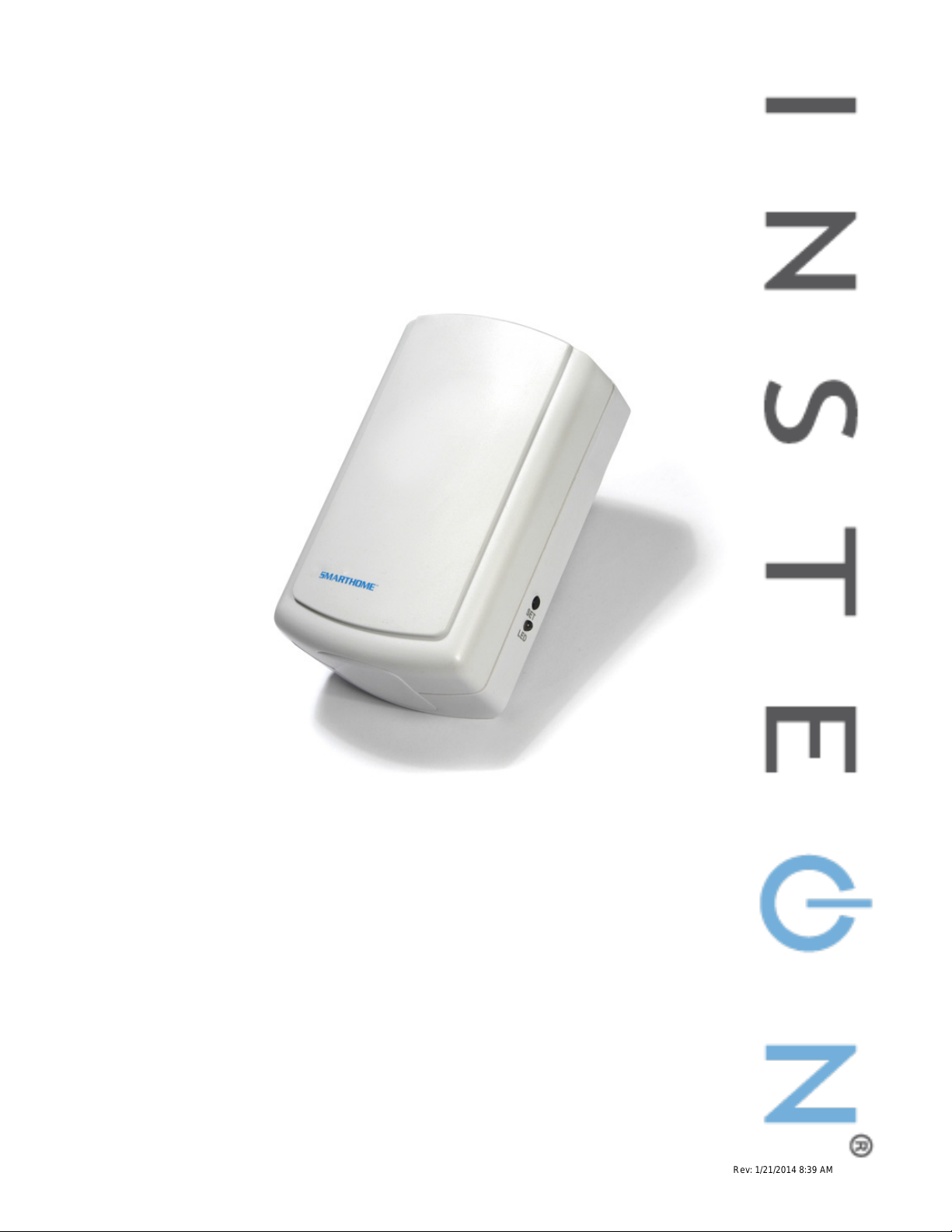
About Dual-Band Access Point
Congratulations on purchasing the INSTEON Dual-Band Access Point. Installing at least two Access
Points in your INSTEON-compatible home will improve INSTEON signal strength and network coverage
throughout your home and provide an int erf ac e betwe en w irel es s -only INSTEON devices and your overall
INSTEON network. Access Points also tie together your dual-band mesh INSTEON network by
transmitting INSTEON signals across radio-frequency to bridge your home’s power line wiring phases.
Features and Benefits
- Quick setup links to other INSTEON devices in minutes
- Beeper and dual-color status LED indicate setup activity
- Communicates simultaneously over both RF and powerline
- Couples INSTEON messages across opposite electrical phases
- Uses the 900MHz band for reliable transmissions, even through walls
- Expands INSTEON networks across large or complex installations
- Approved by the FCC/ETL
- Manufactured in an ISO:9001 certified facility
- Two-year warranty
Page 3 of 8 2443 - Rev: 1/21/2014 8:39 AM
Page 4

What’s in the Box?
If you have any questions, call the INSTEON Support Line at 1-800-762-7845.
- Dual-Band Access Point
- Quick Start Guide
Preparing to Install Access Point
CAUTIONS AND WARNINGS
Read and understand these instructions before installing and retain them for future reference.
This product is intended for installation in accordance with the National Electric Code and local regulations in the United States or
the Canadian Electrical Code and local regulations in Canada. Use indoors only. This product is not designed or approved for
use on power lines other than 120V 60Hz, single phase. Attempting to use this product on non-approved powerlines may have
hazardous consequences.
Recommended installation practices:
- Don’t plug Access Point into an outlet controlled by a switch. If the switch is inadvertent turned off, Access Point will not
have power.
- Don’t plug Access Point into a filtered power strip or AC line filter.
- Install Access Point modules in different areas of your home, keeping them within communication range of each other.
- In multi-story homes, install Access Points on different floors.
- Don’t install Access Point near large metal objects such as a refrigerator, filing cabinet or television. These may absorb
radio-frequency (RF) signals.
- Access Point works best when installed in an open area.
- Unlike many other INSTEON devices, Access Point does not process X10 traffic. In the design of your home auto
IMPORTANT!
Before setting up and using other INSTEON devices, you should properly install at least two Access Points or other dual-band
INSTEON products so that INSTEON messages can travel everywhere in your home. Installing two Access Points will wirelessly
couple the 120V electrical phases in your home. This allows INSTEON devices on one phase to communicate reliably with the
INSTEON devices on the other phase. You can add more Access Points as needed for superior performance and maximized
coverage of your INSTEON network. For larger applications, it is recommended that you install at least one Access Point (or
other dual-band product) for each 750-1,000 s quare f eet.
An Important Note About INSTEON Ne tworks
Split Single-Phase vs. 3-Phase Installation
For the best INSTEON network performance, be sure you have properly installed at least two Access
Points or other dual-band INSTEON products
home. INSTEON has only been officially tested in a split single-phase residential environment, but has
been known to work in many 3-phase systems with three dual-band products installed (one on each
phase). However, due to the potential complexity of its troubleshooting, the INSTEON Support Line is
unable to support INSTEON in 3-phase environments.
to completely bridge the opposite electrical phases in your
Installing Access Points
Installing the First Access Point
1) Plug the first Access Point into a convenient wall outlet. Don’t use an outlet controlled by a switch;
if the switch is inadvertently turned off, Access Point won’t have power.
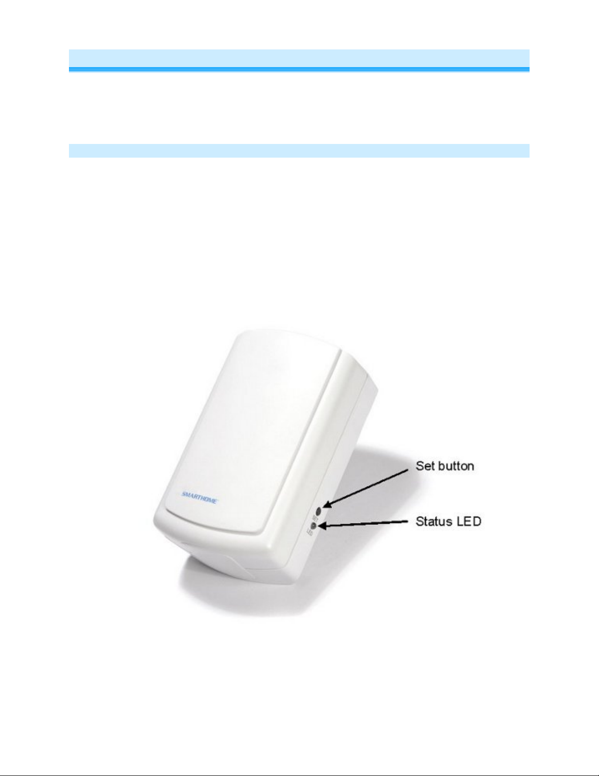
The Access Point LED will turn on dim green.
Tip: choose an outlet that is not near large metal objects that may absorb RF signals.
2) Put the first Access Point into setup mode by rapidly pressing the Set button four times.
Access Point will continuously beep and its LED will turn on bright green.
You will have 9 minutes to install the second Access Point before the first Access Point’s
setup mode times out.
Page 4 of 8 Rev: 1/21/2014 8:39 AM
Page 5

Installing the Second Access Point
Initiator’s (First Access
Point) LED Color
Receivers’ (subsequent
Access Points) LED Color
Resulting Receivers’ LED
Behavior
Installed Correctly - Access Points are installed on opposite electrical phases
Dual-color
White
Bright solid white
White
Dual-color
Blinking green
Installed Incorrectly - Access Points are installed on the same electrical phase and
proper bridging is not occurring
Dual-color
White
Blinking white
Dual
Blinking green/red
Solid green or red
Once you install the first Access Point, you will have about 9 minutes to perform these steps before the
first Access Point’s setup mode times out. If the first Access Point times out, simply follow the steps
above to put it back into setup mode.
1) Plug second Access Point into another unswitched outlet, preferably one located on the other
side of your home.
2) Watch the LED on the second Access Point.
If the LED is blinking green, proceed to step 3.
If the LED is blinking red/green or shining solid red or green, unplug the second Access
Point, plug into a different outlet and repeat steps 1 and 2.
3) Tap the Set button on the first Access Point to exit setup mode.
The first Access Point will stop beeping.
Both Access Points’ LEDs will turn on dim green.
Note: If you can’t locate a pair of outlets on opposite electrical phases, contract your local installer or call
the INSTEON Support Line at 1-800-762-7845.
Installing Additional Access Points
To extend your INSTEON network’s coverage and maximize its performance, you can add additional
Access Points. Simply use the first Access Point that you installed and follow the steps in Insta ll ing the
Second Access Point to confirm that the new Access Points are communicating with your existing
Access Points. After the two opposite electrical phases in your home are bridged w ith at least two
Access Points, it does not matter which electrical phase into which you plug additional Acc ess Points .
Using Access Point Rev 2.0 with Prior Access Point Models
All Access Point models (whether Rev 2.0 or below) are compatible with one another. There are just a
few small differences between the Status LEDs of each model:
• Access Points with Rev 2.0 or higher have a dual-color (red/green) LED
• Access Points models below 2.0 have a white LED
The table below explains the how the different Access Point models will interact with one another.
White
-color
Page 5 of 8 Rev: 1/21/2014 8:39 AM
Page 6

Understanding INSTEON Reliability
General
Product Name
Access Point
Brand
INSTEON
Manufacturer Product Number
2443
UPC
689076406840
Protected under U.S. and foreign patents (see
Status LED
Yes
Available Modes
INSTEON Only
Warranty
Two years, limited
INSTEON Features
INSTEON Powerline Frequency
131.65 KHz
Radio Frequency
915 MHz
INSTEON Messages Repeated
Yes
Mechanical
Dimensions
3 7/8” x 1 1/2” x 2 7/16”
Weight
4.3 oz.
Operating Environm ent
Indoors
Operating Temperature Range
32°F to 104°F
Operating Humidity Range
Up to 85% relative humidity
Electrical
Supply Voltage
120 volts AC +/- 10%, 60 Hertz, single phase
Frequency
120 volts AC +/- 10%, 60 H er t z, single phase
Surge Protection
Rated for 150V
INSTEON messages travel throughout the home via powerline (the existing house wiring) or wirelessly
via RF using Access Points or other dual-band INSTEON products
the INSTEON responders, they are picked up and retransmitted by all other INSTEON devices along the
way. This method of communicating is called a mesh network because every device becomes a signal
repeater. Plus, every INSTEON device confirms that it has received a command. If an INSTEON
controller does not receive this confirmation, it will automatically retransmit the command up to five times.
. As the messages make their way to
Additional Resources
Find home automation solutions, helpful tips, interactive demos, videos, user forums, and more at the
INSTEON Learning Center: www.smarthome.com/learningcenter.html
Specifications
Patent Number
www.insteon.com)
Page 6 of 8 Rev: 1/21/2014 8:39 AM
Page 7

Power Consumption
1.46W
Certification
Safety tested for use in USA and Canada (ETL
FCC ID
SBP2443A
Problem
Possible Cause
Solution
Access Point is not getting
power,
The Status LED on the
Set button.
The Set button wasn’t
four times, or there was too
long a pause between button
taps.
The Access Points are out of
range from each other.
Move the Access Points closer together.
Install a third Access Point between the first
two. See Installing Additional Access Points.
Something made of metal is
blocking the wireless signal.
Move the Access Points away from metal
objects.
A surge or excessive noise on
the powerline may have
locked up Access Point.
Access Point is not designed
to retransmit X10 signals.
Troubleshooting
#3017581)
The Status LED on
Access Point is not
turning on.
first Access Point I
installed is not steadily
bright after I press the
I have tried several
outlets and the second
Access Point is blinking
or steadily dim.
The Status LED has
turned off and does not
flicker during INSTEON
transmissions.
My X10 system
performance is not
improved by insta ll ing
Access Points.
Make sure Access Point is not plugged into a
tapped
switched outlet that is turned off.
Tap the Set button four times in rapid
succession. The Status LED will not change to
steadily bright until after you let go of the Set
button after the fourth tap.
Unplug Access Point, wait 10 seconds, then
plug back in.
Install an X10 phase coupler module.
Install an INSTEON-compatible BoosterLinc
(4827).
If you have tried these solutions, reviewed this Owner's Manual, and still cannot resolve an issue you are
having with Access Point, please call the INSTEON Support Line at 1-800-762-7845.
Page 7 of 8 Rev: 1/21/2014 8:39 AM
Page 8

Certification and Warranty
Certification
This product h as been t horoug hly test ed by ITS ETL S EMKO, a national ly re cogni zed inde pendent third-part y testi ng labo ratory. T he No rth Ameri can
ETL Listed mark signifies that the device has been tes ted to an d has met the requi rements o f a widel y recogni zed conse nsus of U.S. and Canadian
device safety sta ndards, t hat th e manu facturing s ite has b een audi ted, an d that th e manuf acture r has agr eed to a program of quart erly factory foll owup inspections to verify continued conformance.
FCC and Industry Canada Compliance Statement
This device complies with FCC Rules Part 15 and Industry Canada RSS-210 (Rev. 7 or 8). Operation is subject to the following two conditions:
(1) This device may not cause harmful interference, and
(2) This device must accept any interference, including interference that may cause undesired operation of the device.
Le present appareil e st c o nf orm e a u x CNR d' Ind us tri e C a na da appli c ables aux apparei ls r adio exempts de licence. L'exploit ati on es t aut ori s e a u x deux
conditions suivantes:
(1) l'appareil ne doit pas produire de brouillage, et
(2) l'utilisateur de l'appareil doit accepter tout brouillage radiolectrique subi, mme si le brouillage est susceptible d'en compromettre le
fonctionnement.
The digital circuitry of this device has been tested and found to comply with the limits for a Class B digital device, pursuant to Part 15 of the FCC Rules.
These limits are designed to pro vide reasonable protection agai nst harmful inte rference in resid ential installatio ns. This equipm ent generates, uses,
and can radiate radio freque ncy energ y and, if not installe d and used in acco rdance with the instructi ons, may cau se harmful inte rferenc e to radio and
television reception. However, there is no guarantee that interference will not occur in a particular installation. If this device does cause such
interference, whic h ca n be ve ri fie d by turning the device off a nd o n, th e user is encouraged to elim i na te th e i nte rfe re nc e b y one o r m ore of t h e foll o wi ng
measures:
- Re-orient or relocate the receiving antenna of the device experiencing the interference
- Increase the distance between this device and the receiver
- Connect the device to an AC outlet on a circuit different from the one that supplies power to the receiver
- Consult the dealer or an experienced radio/TV technician
WARNING: Changes or modifi cations to t his devic e not expressl y appr oved b y the party res ponsibl e for com plianc e could void the user’s authorit y to
operate the equipment.
ETL/UL Warning (Safety Warning)
CAUTION: To reduc e the risk of overheating and possible damag e to other equipment, d o not install this devic e to control a receptac le, a motor-
operated appliance, a fluorescent lighting fixture, or a transformer-supplied ap pli anc e.
Gradateurs comman dant une lampe a filam ent de tungstene – afin de r eduire le risqué de surc hauffe et la possibil ite d’endommagem ent a d’autres
materiels, ne pas install er pour comm a nde r une pri se, un ap pa rei l a mot eur , une l am pe fluorescente ou un apparei l al i m ente par un transformateur.
Limited Warranty
Seller warrants to the origin al consumer purch aser of this p roduct that, for a period of two years fr om the dat e of purchase, this product will be free
from defects in mate rial and workmanship a nd will perform in substan tial conformity to the descri ption of the product in t his Owner’s Manual. This
warranty shall not appl y to defec ts or errors caus ed by misuse o r neglect. If the product is f ound to be defective in material or workmanshi p, or if the
product does not perform as warr anted above during the warranty perio d, Seller will either repair it, replace it , or refund the purchas e price, at its
option, upon receip t of the p roduct at t he addr ess belo w, pos tage p repai d, with pr oof of th e date of purcha se and a n e xplana tion of th e defec t or e rror.
The repair, replacem ent, or refund that is provided for abov e shall be the full extent of Seller’s lia bility with respect to this product. For repair or
replacement durin g the warra nty peri od, call the INSTEON Support Line at 800-762-7845 with the Model # and R evis ion # of the device to recei ve an
RMA# and send the product, along with all other required materials to:
INSTEON
ATTN: Receiving
16542 Millikan Ave.
Irvine, CA 92606-5027
Limitations
The above warrant y is in lieu of and Seller discl aims all other warranties, w hether oral or written, express or implied, including any warr anty or
merchantability or fitness for a p articular pur pose. Any implie d warranty, incl uding any warra nty of mercha ntability or fit ness for a partic ular purpose,
which may not be di sclaim ed o r su ppla nted as prov ided above shal l be li mited to the t wo-year of the express warrant y above. No other re presenta tion
or claim of any nature by any person shall be binding upon Seller or modify the terms of the above warranty and disclaimer.
Home automation devices have the risk of failure to operate, incorrect operation, or electrical or mechanical tampering. For optimal use, manually verify
the device state. Any home automation device should be viewed as a convenience, but not as a sole method for controlling your home.
In no event shall Seller be liable f or special, inci dental, conseque ntial, or other dam ages resulting f rom possession or use of this device, i ncluding
without limitation damage to pr op ert y a nd, to t he e xt ent p erm i tte d by law, personal injury, even if Sel le r knew or shoul d h ave known of the possibility of
such damages. Som e st at es d o n ot all ow limitations on ho w l on g an im pl i ed w arr an t y last s an d/o r th e e xcl us io n o r l im it ation of d amages, in which c ase
the above limitations and/or excl usi o ns m a y not appl y to you . Yo u ma y also ha ve othe r legal rig hts tha t ma y var y from stat e to state.
Protected under U.S. and foreign patents (see www.insteon.com).
© Copyright 2012 INSTEON, 16542 Millikan Ave., Irvi ne, C A 9260 6, 800-762-7845, www.insteon.com
Page 8 of 8 Rev: 1/21/2014 8:39 AM
 Loading...