

Page 1

SynchroLinc
Model : 2423A5
Power-Synching INSTEON® Controller
Page 2

SynchroLinc Owner’s Manual
TABLE OF CONTENTS
ABOUT SYNCHROLINC .............................................................................................................................. 3
Key SynchroLinc Features ........................................................................................................................ 3
What is Included with SynchroLinc ............................................................................................................ 3
WHAT IS INSTEON? .................................................................................................................................... 4
INSTALLATION ............................................................................................................................................ 4
Preparing to Install SynchroLinc ................................................................................................................ 4
Product Use Restrictions ........................................................................................................................... 5
Installing SynchroLinc ................................................................................................................................ 5
Calibrating SynchroLinc ............................................................................................................................. 5
USING SYNCHROLINC IN A LOAD SENSE SCENE ................................................................................. 6
Creating a Load Sense Scene with SynchroL inc ...................................................................................... 6
Linking SynchroLinc to an INSTEON Responder ..................................................................................... 6
Unlinking an INSTEON Responder from SynchroLinc .............................................................................. 6
ADVANCED FEATURES ............................................................................................................................. 7
Advanced Calibration ................................................................................................................................ 7
Using a Second Load Sense Scene with S ynchroL inc ............................................................................. 7
Restoring Power to SynchroLinc ............................................................................................................... 8
Resetting SynchroLinc to its Factory Default Settings .............................................................................. 8
ABOUT INSTEON ........................................................................................................................................ 9
Using Dual-Band INSTEON Devices to Upgrade Your Network ............................................................... 9
Important Note about INSTEON Networks; Split Single-Phase vs. 3-Phase Ins ta lla tion .......................... 9
Further Enhancing Reliability .................................................................................................................... 9
ADDITIONAL RESOURCES ........................................................................................................................ 9
TROUBLESHOOTING ................................................................................................................................ 10
SPECIFICATIONS, CERTIFICATION, AND WARRANTY ........................................................................ 11
Specifications .......................................................................................................................................... 11
Certification .............................................................................................................................................. 11
Limited Warranty ..................................................................................................................................... 11
Page 3
SynchroLinc Owner’s Manual
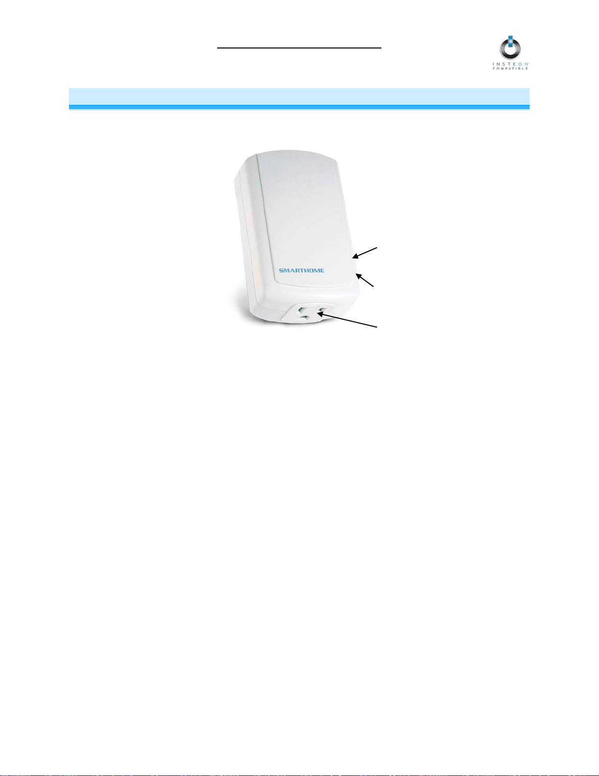
Set button
Status LED
Outlet
ABOUT SYNCHROLINC
SynchroLinc allows you to create Load Sense scenes to c ontrol other INSTEON de vices, based on the
power state of the load plugged into SynchroLinc.
Key SynchroLinc Features
• Installs and Links to controlled devices in minutes
• Monitors loads with minimum of 7 Watts up to 1800 Watts (15 Amps at 120V)
• Triggers devices in programmed INSTEON scenes
• Indicates INSTEON setup mode activity and operational states with a dual-color Status LED and
beeper
• Stores setup state in memory so settings aren’t lost during power outages
• Two-year warranty
What is Included with SynchroLinc
• SynchroLinc – Power-Synching INSTEON Controller
• Quick-Start Guide
Page 3 of 12
Page 4

SynchroLinc Owner’s Manual
WHAT IS INSTEON?
Since its inception in 2005, INSTEON has become a best-selling home-control network ing technology,
offering more reliability and flexibility than any other home management system on the market. INSTEON
systems are sim ple, reliable, a nd affor dable. Simple, because each device tak es mere m inutes to insta ll.
Reliable, because ever y INST EON dev ice work s as a network repeater, e nsurin g your c omm ands will not
be lost. Affordable, bec ause INST EON can be int egrated i nto any num ber of devic es easil y and at a very
low cost. An INSTEON home grows in value with each added INSTEON device, making life more
convenient, safe, and fun.
How Does INSTEON Work?
What makes INSTEON the most reliable home automation network is its dual-mesh network. INSTEON
devices use both radio frequency (RF) signals and the home’s existing wiring to talk to each other. In an
INSTEON network, every INSTEON device also acts as a repeater, receiving and sending every message to all
other devices in the network. So by integrating more INSTEON devices you will strengthen the network and
ensure no commands will be lost.
No central controller or networking setup is required with an INSTEON network. Simply install your devices and
then use a series of button presses or taps to Link your devices together. Throughout this Owner’s Manual, you
may see the terms “Controller” or “Responder”. These generic INSTEON terms refer to the components of an
INSTEON scene, and are used on a scene-by-scene basis.
• Controller – sends INSTEON commands to other devices
• Responder – reacts to commands sent out by another INSTEON device
An INSTEON device may act as a Controller, Responder, or sometimes both.
INSTEON networks are also extremely secure. Each INSTEON device is assigned a unique INSTEON ID, so
unless neighbors or would-be hackers have access to your particular device’s INSTEON ID, they won’t be able
to control your home, even if they are using similar products.
INSTALLATION
Preparing to Install SynchroLinc
CAUTION
Read and understand these instructions before installing and retain them for future reference.
SynchroLinc is intended for installation in accordance with the National Electric Code and local
regulations in the United States or the Canadian Electr ical Code and local regulations in Canada. Use
indoors only. SynchroLinc is not designed nor ap proved for use on power lines other than 120V 60H z,
single phase. Attempting to use SynchroLinc on non-approved power lines may have hazardous
consequences.
Prior to installing SynchroLinc, please review the entire installation procedure and take the following
precautions:
• Use indoors or in a properly insulated and weatherproof electrical box only
• Don’t plug SynchroLinc into an out let contr olled b y a switch b ecause if the sw itch is inadvertent ly
turned off, SynchroLinc won’t have power
• Don’t plug SynchroLinc into a filtered power strip or AC filter
If you have any questions, please call:
INSTEON Gold Support Line
800-762-7845
Page 4 of 12
Page 5

SynchroLinc Owner’s Manual
Product Use Restrictions
Use only as directed in the instr uctions an d within th e spec ifications and envir onm ental conditions below.
Using SynchroLinc in a different m anner or outside the conditions b elow may defeat the safety features
and protection against electrical shock and fire.
• 120 Volts AC +/- 10%, 60 Her t z, 15 Am ps maximu m c ontinuous
• Indoor use only
• Temperature 41° to 104° F (5° to 40° C)
• Maximum relative humidity 80% for temperatures up to 87° F (31° C) decreasing linearly to 50%
relative humidity at 104° F (40° C)
• Altitude up to 6,500 feet (2,000 meters)
• Installation Category II
• Pollution Degree 2
Installing SynchroLinc
1) Plug the desired device (also called the load) into the outlet on SynchroLinc
2) Plug SynchroLinc into an unswitched outlet
SynchroLinc will beep
The SynchroLinc Status LED will turn on solid green or solid red
After 20 seconds, SynchroLinc will double-beep and enter Calibration Mode
You will have 4 minutes to calibrate SynchroLinc before Calibration Mode automatically times out.
Once Calibration Mode times out, SynchroLinc will ignore all button taps.
NOTE: If you plan t o us e SynchroLinc with INSTEON hom e autom ation soft ware (e.g., HouseL inc 2), wait
until SynchroLinc enters Calibration Mode (after the double-beep) to add it to the software.
Calibrating SynchroLinc
1) Make sure the load is off or in its standby state
2) Wait at least 10 seconds and then tap the Set button on SynchroLinc to rec ord the off/low energy
state
SynchroLinc will beep
3) Turn the load on or set it to its high energy state
4) Wait at least 10 seconds and then tap the Set button to record the on/high energy state
SynchroLinc will double-beep and its Status LED will turn on solid green when the lo ad is in its
high energy state and red when it is in its low energy state
If you would like to reset t he energy states or if SynchroLinc t imes out of Calibration Mod e, unplug the
SynchroLinc and reinstall. See Installing SynchroLinc.
Page 5 of 12
Page 6

SynchroLinc Owner’s Manual
USING SYNCHROLINC IN A LOAD SENSE SCE NE
Creating a Load Sense Scene with SynchroLinc
A Load Sense scene allows you to control other INSTEON devices based on the energy level of the load. For
example, you could create a scene that turns on your surround sound system when your DVD playe r (the load)
is turned on.
The scene will be activated when the load reaches its high energy state. When the load reaches the low energy
state, all Linked Responders will also turn off.
NOTE: To create Load Sense Scenes, you must first lock in the high and low energy states of the load. See
Calibrating SynchroLinc.
As an advanced feature, SynchroLinc is capable of storing two scenes. See Using a Second Load Sense
Scene with SynchroLinc.
Linking SynchroLinc to an INSTEON Responder
Once you have locked-in the load’s energy states, you can Link S ynchroLinc to the desired Responders and
complete the Load Sense scene. See your Responder’s Owner’s Manual for more detailed instructions on how
to Link it to SynchroLinc.
The following will work for the most common INSTEON devices:
1) At the Responder, set it to the state you wish to be activated f rom SynchroLinc when the load reaches its
high energy state (turn it on if you wish it to be on or off if you wish it to be off when SynchroLinc activates
the scene, set brightness levels, etc.)
2) Set SynchroLinc to Linking Mode by pressing & holding the Set button until it beeps (3 seconds)
The SynchroLinc Status LED
You will have 4 minutes to complete the next step before Linking Mode automatically times out.
3) Press & hold the Responder’s Set button for 3 seconds
SynchroLinc
energy state and red when it is in its low energy state
4) Confirm that Linking was successful by turning the load on and off
The Responder
5) If you wish to Link additional devices to the scene, repeat steps 1-4 with each additional Responder
will begin blinking green
will double-beep and its Status LED will turn on solid green when the load is in its high
will respond appropriately
Unlinking an INSTEON Responder from SynchroLinc
If you are no longer going to use an INSTEON Responder that has previously been Link ed to SynchroLinc, it is
very important that you Unlink it. Otherwise, SynchroLinc will retry any commands repetitively, thus slowing
down the system.
The following will work on the most common INSTEON devices:
1) If the Responder is a multi-scene device, tap the Scene button you wish to remove control from until its
LED illuminates
2) Set SynchroLinc to Linking Mode by pressing & holding the Set button until it beeps (3 seconds)
The SynchroLinc Status LED
3) Set SynchroLinc to Unlinking Mode by pressing & holding the Set button until it beeps again (3 seconds)
The SynchroLinc Status LED will begin blinking red
You will have 4 minutes to complete the next step before Unlinking Mode automatically times out.
4) Press & hold the Responder’s Set button for 3 seconds
SynchroLinc
energy state and red when it is in its low energy state
5) Confirm that Unlinking was successful by turning the load on and off
The Responder
will double-beep and its Status LED will turn on solid green when the load is in its high
will no longer respond
will begin blinking green
Page 6 of 12
Page 7

SynchroLinc Owner’s Manual
ADVANCED FEATURES
Advanced Calibration
SynchroLinc uses a trigger point to determine if the load is in the high or low energ y state and send the
appropriate commands. If power consumption of the load is below the trigger point, SynchroLinc
considers the load to be at its low energ y state. If power cons umption is above the trigger poi nt, the load
is in its high energy state. The trigger point may differ depending on how SynchroLinc is calibrated.
If the low energ y state is l o ck ed in f irs t dur in g C al ibrat i on Mode (as described in C alibr at ing Sync hroLinc),
SynchroLinc will set the tri g ger poi nt at 25% above the low energy level. Ho we ver, if the high e nergy state
is locked in first, the trigger point will be set at 25% below the high energ y level.
For example, if the lo w energy state is locked in fir st at 0 Watts and the high energ y state is locked in
second at 100W, the trigger point will be set at 25W.
If the high energy state is l oc ked in first at 100W and the lo w en ergy state is locked in second at 25W, the
trigger point will be set at 75W.
NOTE: Trigger point can be manually adjusted when used with INSTEON home automation software,
such as HouseLinc 2.
Using a Second Load Sense Scene with SynchroLinc
As an advanced feature, SynchroLinc is capable of storing two scenes, referred to as Scenes 1
(described in Creating a Load Sense Scene with SynchroLinc) and 2.
• Scene 1 is activated when the loa d reaches its high energy state
NOTE: W ithout Sce ne 2 se t up, all L inked Resp onders w ill turn of f when the load reac hes its lo w
energy state.
• Scene 2 is activated when the loa d reaches its low energy state
Depending on how you p la n to us e SynchroLinc, you might need to s e t up b oth scenes. For example, you
might want your lights to dim f rom f ull-bright to 50% brightness when your DVD pl a yer turns on (Sc e ne 1),
and return to full-bright when your DVD player turns off (Scene 2).
See Linking SynchroLinc to an INSTEON Responder to Link Scene 1.
To Link to Scene 2:
1) At the Responder, set it to the state you wish to be activated from SynchroLinc when the load
reaches its low energy state (turn it on if you wish it to be on or off if you wish it to be off when
SynchroLinc activates the scene, set brightness levels, etc.)
2) Set SynchroLinc to Linking Mode by pressing & holding the Set button until it beeps (3 seconds)
The SynchroLinc Status LED will begin blinking green
3) Set SynchroLinc to Unlinking Mode by pressing & holding the Set button until it beeps again (3
seconds)
The SynchroLinc Status LED will begin blinking red
4) Press & hold the Set button until it beeps a third time (3 seconds)
The SynchroLinc Status LED will begin blinking green
You will have 4 minutes to complete the next step before Linking Mode automatically times out.
5) Press & hold the Responder’s Set button for 3 seconds
SynchroLinc will double-beep and its St atus LED will turn on solid green when the load is in its
high energy state and red when it is in its low energy state
6) Confirm that Linking was successful by turning the load on and off
The Responder will respond appropriately
7) If you wish to Link additional devices to Scene 2, repeat steps 1-6 with each additional Responder
Page 7 of 12
Page 8

SynchroLinc Owner’s Manual
To Unlink from Scene 2:
1) If the Responder is a multi-sc ene device, tap the Scen e button you wish to rem ove control from until
its LED illuminates
2) Set SynchroLinc to Linking Mode by pressing & holding the Set button until it beeps (3 seconds)
The SynchroLinc Status LED will begin blinking green
3) Set SynchroLinc to Unlinking Mode by pressing & holding the Set button until it beeps again (3
seconds)
The SynchroLinc Status LED will begin blinking red
4) Press & hold the Set button until it beeps a third time (3 seconds)
The SynchroLinc Status LED will begin blinking green
5) Press & hold the Set button until it beeps a fourth time (3 seconds)
The SynchroLinc Status LED will begin blinking red
You will have 4 minutes to complete the next step before Unlinking Mode automatically times out.
6) Press & hold the Responder’s Set button for 3 seconds
SynchroLinc will double-beep and its St atus LED will turn on solid green when the load is in its
high energy state and red when it is in its low energy state
7) Confirm that Unlinking was successful by turning the load on and off
The Responder will no longer respond
Restoring Power to SynchroLinc
SynchroLinc s tores al l of its settin gs, s uch as Li nk s to other IN ST EON de vices, with non-volatil e m emor y.
Because settings are saved in this non-volatile memory, they will not be lost in the event of a power
failure.
Additionally, in the event of a power loss, SynchroLinc will not resend ON/OFF commands to the
INSTEON devices it is Linked to.
Resetting SynchroLinc to its Factory Default Settings
The factory reset procedure will clear SynchroLinc of all INSTEON Links.
NOTE: Resetting Synchr oLinc does not remove the high/low ener gy states stored during calibration. T o
reset the high/low energy states, see Calibrating SynchroLinc.
1) If you are using SynchroLinc to control any INSTEON devices, Unlink those devices from
SynchroLinc. See Unlinking an INSTEON Responder from SynchroLinc.
2) Unplug SynchroLinc for about 10 seconds
3) While holding down the Set but ton on SynchroLinc , plug it back in, m aking sure not to let up on the
Set button
SynchroLinc will beep and its Status LED will turn on solid green or red
4) Continue to hold down the Set button for 3 seconds and then release
After a few seconds, SynchroLinc will double-beep and its Status LED will switch colors
Page 8 of 12
Page 9

SynchroLinc Owner’s Manual
ABOUT INSTEON
Using Dual-Band INSTEON Devices to Upgrade Your Network
What are phases?
The majority of single-family homes in North America have two phases (or “legs”) of 110 Volts coming into their
electricity panels. From the panel, they are distributed throughout the home, providing power to outlets and wall
switches. These phases come together in some parts of the home to provide 220 Volts of power to large
appliances, such as an electric oven or pool pump.
Why do I need to bridge these phases?
Single-band power line devices send commands via the home’s electricity, but only on a single phase. If the
command is intended for a device on the opposite phase, there is a good chance the command will go
unnoticed. Installing dual-band INSTEON devices, such as Access Points (#2443), on each phase will allow for
devices to communicate between the two phases via RF.
Dual-band INSTEON devices embody the full potential of a true INSTEON mesh network. Taking the power
line band signal and working in conjunction with the RF band signal, its dual-band function plays out in two
ways:
• Phase bridger – a receiver of commands, reacting to and translating signals sent from one power
phase to the opposite via RF
• Signal repeater – a participant in an INSTEON network, repeating commands intended for other
devices whether those commands are generated from RF or power line-only devices. To ensure
reliability, every INSTEON device confirms that it has received a command. If a Controll er does not
receive this confirmation, it will automatically retransmit the command up to five times.
While using at least one dual-band device is required when using an RF-only de vice, at least two dual-band
devices are recommended to ensure reliable communication across two-phase home wiring systems. For
larger applications, it is recommended to install at least one dual-band device fo r every 750 – 1,000 square
feet.
Search for dual-band INSTEON devices at: www.smarthome.com/dualband
Important Note about INSTEON Networks; Split Single-Phase vs. 3-Phase Installation
For the best INSTEON network performance, be sure you have properly installed at least two dual-band
INSTEON devices. INSTEON has only been officially tested in a split single-phase residential environment but
has been known to work in many 3-phase systems, where three dual-band devices are used (one on each
phase). However, due to the potential complexity of its troubleshooting, the INSTEON Gold Support Line is
unable to support INSTEON in 3-phase environments.
Further Enhancing Reliability
As signals travel via the power line or RF throughout the home, they naturally beco me weaker the farther they
travel. The best way to overcome weakened signals is to increase the coverage of the mesh network by
introducing more INSTEON devices.
It is possible that some audio-video devices, computers, power strips, or other electrical equipment may
attenuate INSTEON signals on the power line. You can temporarily unplug suspected devic es to test whether
the INSTEON signal improves. If it does, then you can plug in filters that will permanently fix the problem.
ADDITIONAL RESOURCES
Find home automation solutions, helpful tips, interactive demos, videos, user forums, and more at the
Smarthome Learning Center: www.smarthome.com/learningcenter.html
Page 9 of 12
Page 10

Problem
Possible Cause
Solution
The Responder might
from it.
SynchroLinc and the
phases.
Add additional INSTEON devices or move around
act as INSTEON network repeaters.
Large appliances, such as
on the power line.
Other electrical devices,
the INSTEON signal.
Unlink any unused Responders from SynchroLinc.
eliminate unnecessary Links.
SynchroLinc turns off
SynchroLinc.
If the above doesn’t work, perform a factory reset.
Settings.
TROUBLESHOOTING
SynchroLinc Owner’s Manual
The Status LED on
SynchroLinc is not
turning on at all.
Responders are not
being controlled after
I’ve created a Load
Sense scene with
SynchroLinc.
SynchroLinc ma y not be
getting power.
have been reset without
Unlinking SynchroLinc
Responders may be on
opposite power line
The INSTEON signal may
be too weak.
refrigerators or air
conditioners, ma y be
producing electrical noise
such as computers,
televisions, or power
strips, may be absorbing
Make sure SynchroLinc is not plugged into a
switched outlet that is turned off.
Re-Link SynchroLinc to the Responder.
Make sure two dual-band INSTEON devic es ar e
properly installed to bridge the two power line
phases.
existing INSTEON devices. All INSTEON devices
Install a power line noise filter (#1626-10) to filter
electrical noise and minimize signal attenuation.
Responders are taking
a long time to respond
to SynchroLinc.
a Responder but
nothing happens when
an ON command is
sent from
SynchroLinc is lock ed
up.
SynchroLinc does not
beep or double-beep
when I tap the Set
button to calibrate
SynchroLinc.
SynchroLinc ma y be
sending commands to a
Responder that is no
longer in use. Commands
for the unused Responder
are being resent and
loading down the signal.
The Responder may be
Linked at its off state.
A surge or excessive
noise on the power line
may have glitched it.
SynchroLinc may have
timed out of Calibration
Mode. Once timed out,
SynchroLinc will not
respond to button presses.
HINT: If you are using home automation software,
you can easily check scene membership and
If the above doesn’t work, perform a factory reset.
Re-Link the Responder to SynchroLinc, while the
Responder’s load is on. See the Responder’s
Owner’s Manual for more detailed Linking
instructions.
Unplug SynchroLinc for 10 seconds and reinstall.
See Resetting SynchroLinc to its Factory Default
Unplug SynchroLinc for at least 10 seconds. Then,
reinstall and recalibrate SynchroLinc. See
Installing SynchroLinc.
Page 10 of 12
Page 11

SynchroLinc Owner’s Manual
Problem
Possible Cause
Solution
SynchroLinc might have
2 will recognize it.
SynchroLinc is
red.
Additional Troubleshooting with HouseLinc 2:
HouseLinc 2 is not
recognizing
SynchroLinc or it lists
it as a “PowerLinc
Modem”.
sending ON/OFF
commands repeatedly
and its Status LED is
flashing green and
If you have tried these solutions, reviewed th is Owner’s Manual, and st ill cannot r esolve an issue you are
having with SynchroLinc, please call:
been added to HouseLinc
2 too soon. It needs to be
powered for at least 20
seconds before HouseLinc
Triggers, delay, and/or
tolerance may be set too
close to the load’s power
level.
INSTEON Gold Support Line
800-762-7845
Delete the PowerLinc Modem from HouseLinc 2
and unplug SynchroLinc. Wait at least 10 seconds
and then reinstall SynchroLinc. Once SynchroLinc
beeps to enter Calibration Mode (20 seconds), add
SynchroLinc to HouseLinc 2.
Turn the load attached to SynchroLinc off. Then, in
HouseLinc 2, choose SynchroLinc from the
Devices list and select the Properties tab. Increase
the delay and tolerance or decrease the trigger
point.
SPECIFICATIONS, CERTIFICATION, AND WARRANTY
Specifications
View specifications for SynchroLinc at: www.smarthome.com/2423A5.html
Certification
SynchroLinc has been thoroughly tested by Internek Testing Services NA, a nationally recognized
independent third-party testing laborator y. The North American ETL L isted mark sign ifies that the device
has been tested to and has met the requirements of a widely recognized consensus of U.S. and
Canadian device safety standards, that the manufacturing site has been audited, and that the
manufacturer has agreed to a program of quarterly factory follow-up inspections to verify continued
conformance.
Limited Warranty
Seller warrants to the original consumer of this product that, for a period of two years from the date of
purchase, this product will be free from defects in material and workmanship and will perform in
substantial conform ity to th e description of the product in this Owner’s Manua l. This warranty shall not
apply to defects or er rors caused b y misuse or neg lect. If the product is f ound to be def ective in m aterial
or workmanship, or if the product do es not p erf orm as warranted ab ove dur ing the warra nty peri od, Sel ler
will either re pa ir it, r ep lace it , or r efund th e purchas e pric e, at its optio n, upon rec eipt of the pr oduct at t he
address below, postage pr epaid, with proof of the date of purchas e and an explanation of the defect or
error. The repair, replacement , or refund that is provided for above sha ll be the full extent of the Seller’s
liability with respect to this product. For repair or replacement during the warranty period, call the
INSETON Gold Support Line at 800-762-7845 with t he Model # and Revision # of the device to receive
an RMA# and send the product, along with all other required materials to:
Smarthome, Inc.
ATTN: Receiving Dept.
16542 Millikan Ave.
Irvine, CA 92606-5027
Page 11 of 12
Page 12

SynchroLinc Owner’s Manual
Limitations
The above warranty is in l ieu of and Seller disc laims all other warrant ies, wheth er oral or writt en, expr ess
or implied, including any warranty or merchantability or fitness for a particular purpose. Any implied
warranty, including any warranty of m erchantability or f itness for a particular purpose, which m ay not be
disclaimed or supplanted as provided above shall be limited to the two-year of the express warranty
above. No other representation or claim of any nature by any person shall be binding upon Seller or
modify the terms of the above warranty and disclaimer.
Home automation devices have the risk of failure to operate, incorrect operation, or electrical or
mechanical tam pering. For optimal use, manuall y verify the device state. Any h ome automation device
should be viewed as a convenience, but not as a sole method for controlling your home.
In no event shall Seller be liable for special, incident al, consequential, or other dam ages resulting from
possession or use of this device, including without limitation damage to property and, to the extent
permitted by law, personal injury, even if Seller knew or should have known of the possibility of such
damages. Some states do not allow limitations on how long an implied warranty lasts and/or the exclusion
or limitation of dam ages, in which c ase the abo ve lim itations and/or exclus ions m ay not app l y to you. You
may also have other legal rights that may vary from state to state.
INSTEON Technology Patent
U.S Patent No. 7,345,998, International patents pending
© Copyright 2011
Smarthome, 16542 Millikan Ave., Irvine, CA 92606, 800-762-7845, www.smarthome.com
Rev 04-06-2011
Page 12 of 12
 Loading...