

Page 1
Mini Remote
INSTEON® Remote Control Switch
(formerly RemoteLinc 2)
Owners Manual
2342-242, 2444A3 (US)
2342-442 (EU)
2342-542 (AUS/NZ)
Page 1 of 16 2342-242/2444A3, 2342-442, 2342-542 Rev: 1/21/2014 7:24 AM
Page 2

About Mini Remote ..................................................................................................................................... 3
Features & Benefits .................................................................................................................................... 4
What’s in the Box? ..................................................................................................................................... 4
Required Accessories ................................................................................................................................ 4
Optional Accessories ................................................................................................................................. 5
Getting Started ............................................................................................................................................ 6
Scenes .......................................................................................................................................................... 6
Add Mini Remote Button to a Scene as a Controller ................................................................................. 6
Remove Mini Remote Button from a Scene as a Controller ..................................................................... 6
Using Mini Remote ...................................................................................................................................... 7
LED Behavior ............................................................................................................................................ 8
Turn Unit On/Off (Pocket Mode) ................................................................................................................ 8
Stuck button ............................................................................................................................................... 8
Advanced Features ..................................................................................................................................... 8
Add Multiple Responders to a Scene (Multi-Link) ..................................................................................... 8
Remove Multiple Responders from a Scene (Multi-Unlink) ...................................................................... 9
Change Paddle / Scene Configuration (e.g. Change to 2 Scene Mode) .................................................. 9
Turn LED Off (or Back On) ...................................................................................................................... 10
Turn Beeper On During Usage (or Back Off) .......................................................................................... 10
Beeper Behavior ...................................................................................................................................... 11
LED Behavior during Setup ..................................................................................................................... 11
Factory Reset .......................................................................................................................................... 11
Specifications ............................................................................................................................................ 12
Troubleshooting ........................................................................................................................................ 13
Certification and Warranty ....................................................................................................................... 15
FCC & Industry Canada Compliance Statement ..................................................................................... 15
Limited Warranty ..................................................................................................................................... 16
Limitations ............................................................................................................................................ 16
Page 2 of 16 2342-242/2444A3, 2342-442, 2342-542 Rev: 1/21/2014 7:24 AM
Page 3
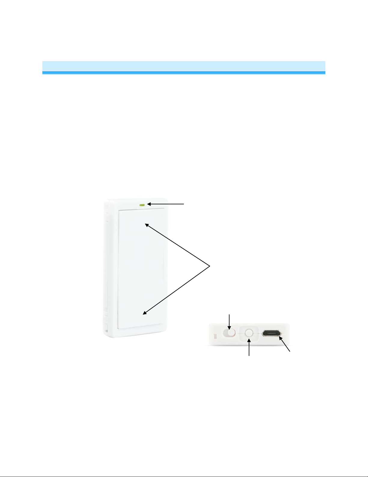
Paddle
Status LED
Power/Recharging Jack
(Micro-USB, 5VDC)
Set
button
On/Off switch
About Mini Remote
Mini Remote is the smallest and most versatile INSTEON Remote Control in the world. The 1 Scene
Controller can easil y be reconfigured to give you tog gle control of up to 2 scenes and/or de vices. Mini
Remote can be:
- Handheld (wireless remote)
- Mounted on wall with no trim plate (wireless keypad)
- Mounted on wall in a single-gang Decorator trim plate (wireless keypad, built-in look)
- Mounted on wall in a multi-gang Decor ator trim plate (add to the number of c ontrollers in your room
without hiring an electrician and/or tearing out drywall)
- Placed on a Tabletop Stand (sold separately)
- Clipped to your car’s visor with Visor Clip (sold separately)
Top On, Bottom Off
(1 scene mode)
Top On/Off, Bottom On/Off
(2 scene mode)
Page 3 of 16 2342-242/2444A3, 2342-442, 2342-542 Rev: 1/21/2014 7:24 AM
Page 4
Features & Benefits
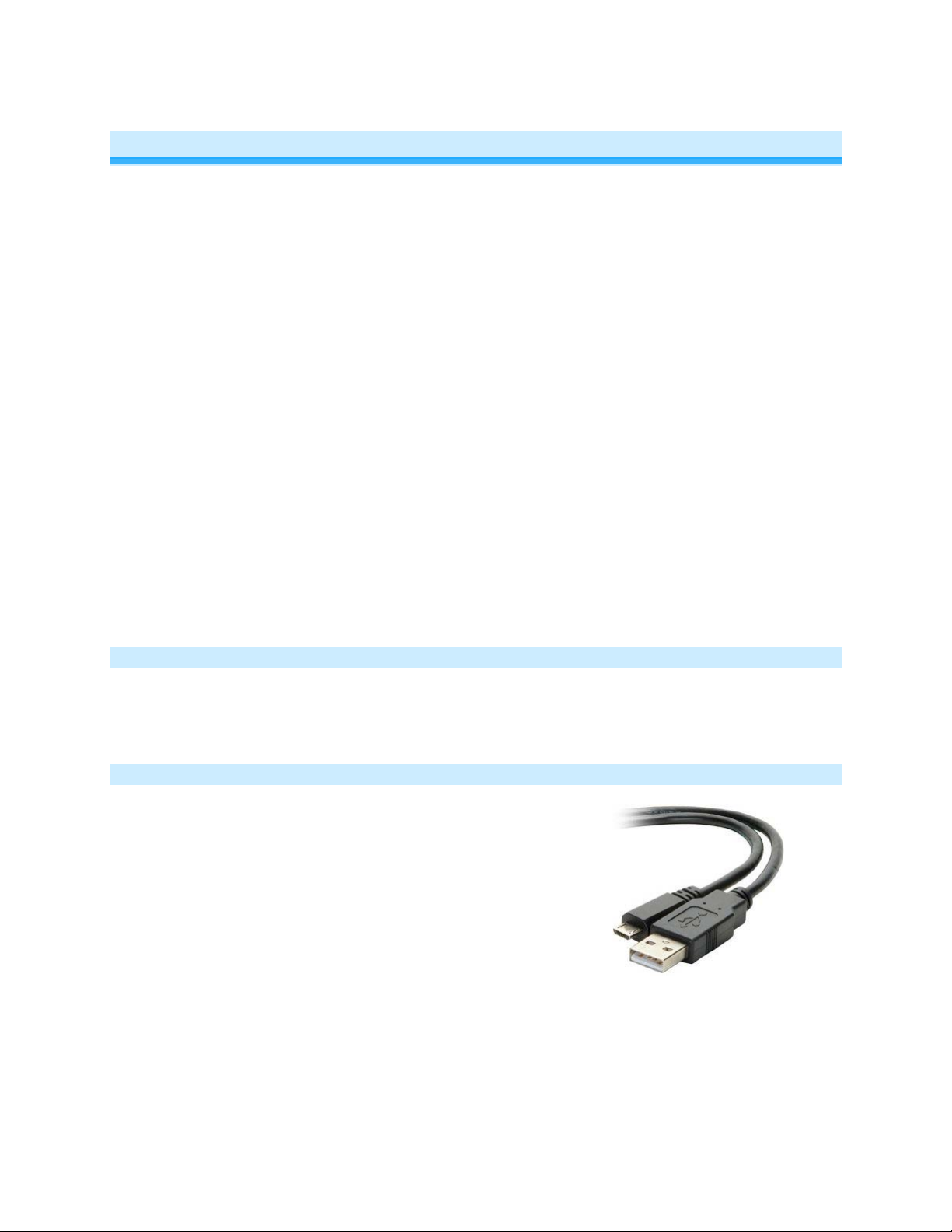
Type A to Micro-B cable
(2444B5)
• Small, elegant design
• Super-easy setup
• Rechargeable battery included
• Discreet On and Off buttons for 1 Scene
• Can be reconfigured for 2 Scene triggers or 2 Scene On/Off toggle control
• Can be installed into a single Decora opening (requires Wall-Mount Bracket)
• Can be used as a table-top controller (requires Tabletop Stand)
• Can be used as a visor-mounted remote control for lights, garage door opener etc. (requires Visor
Clip)
• LED blinks green when Turning a Scene On and red when turning a Scene Off
• Slide switch for disabling buttons (“vacation” or “pocket” mode)
• Stuck Button Mode – saves battery life by going to sleep if button stuck down
• Beeper for setup ease
• Recharges with standard USB charger with via Micro-USB Plug (5VDC)
• Battery life exceeds 3 months
• Battery charge LED indicator built-in
• Low battery transmit warning (use with software to trigger email/text message)
• All settings stored in stable memory which is maintained even without power
• 2 year warranty
What’s in the Box?
• Mini Remote
• Rechargeable battery (pre-installed)
• Quick-Start Guide
Required Accessories
• A micro USB cable for connecting and recharging Mini Remote via USB
port on a computer or USB power adapter.
• If the INSTEON device you intend to control does not receive RF signals
(i.e., power line only), you will need at least one dual-band INSTEON
device to convert the RF signals to power line signals.
Page 4 of 16 2342-242/2444A3, 2342-442, 2342-542 Rev: 1/21/2014 7:24 AM
Page 5
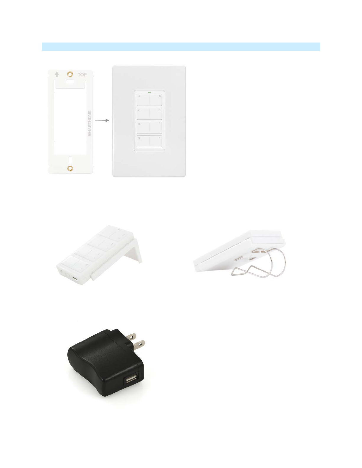
Optional Accessories
Visor Clip
Tabletop Stand
USB Power Adapter
Wall Mount Bracket
Pair the Wall Mount Bracket with any decorator style
wall plate (sold separately) for the perfect wireless
wall switch solution.
• Perfect for a nightstand, kitchen counter or
(Available in the 2444Bxx kit)
coffee table
(2444B4)
• Wall mount your Mini Remote anywhere
• Gang two or more together for more control
• Can be installed adjacent to existing wired-in switche s
• Mini Remote can easily be removed for portability or
recharging
• Use with any decorator wallplate
•
(Available in the 2444Bxx kit)
• Control your home from your vehicle
• Turn lights on when you arrive and off as
you leave
(2444B6)
• For use with Mini Remote USB Charging
Cable and any other device that charges
via USB cable
Page 5 of 16 2342-242/2444A3, 2342-442, 2342-542 Rev: 1/21/2014 7:24 AM
Page 6

Getting Started
Fully charge your Mi ni Rem ote prior to programming or anytime the unit is not responding. Mini Remote
charges via a USB cable (Type A to Micro-B, sold separately). The red charging LED will turn off once the
battery has been fully charged (approximately 1 hour). To turn on Mini Remote, simply slide the power
switch to the on position.
Note: Mini Remote uses a subtle beeper sound to assist setup. It is recommended that you program the
unit in a quiet area.
Scenes
Scene: One or more INSTEON devices which respond to an INSTEON controller. When the scene is
activated (turned “on”), all devices return to the states they were at when the scene was programm ed.
INSTEON scenes let you activate dramatic lighting moods at the touch of a button. For example, you can
set all the lights in a scene to dim to 50% or turn certain lights on while turning others off, all with the tap
of a button on any INSTEON Controller. INSTEON scenes are easy to set up, just follow the directions
below.
Maximum number of scenes in Mini Remote Switch: 2 (Default is 1)
Scene Control Functions supported; On, Off, Press & hold Bright, Press & hold Dim, Double-tap Fast On
and Double-tap Fast Off.
Add Mini Remote Button to a Scene as a Controller
Follow the steps below to control a scene (one or more INSTEON devices).
1) Tap the Mini Remote switch (top or bottom paddle) – if in 2 scene mode, tap the top of the paddle for
scene 1 or the bottom for scene 2
2) Adjust the scene responder to the “state” you want when the scene is activated from Mini Remote
(e.g., 50%, 25% or even OFF)
1
3) Press & hold Mini Remote’s Set button until Mini Remote beeps
Mini Remote’s LED will blink green
4) Press & hold the responder’s Set button until it beeps (or until its LED/ l oad flashes)
Mini Remote will double-beep and its LED will stop blinking
Responder’s LED will stop blinking (it may also double-beep)
5) Confirm that scene addition was successful by tapping on/off on your Mini Remote
The Responder will toggle between the Scene on level and off
6) If you wish to add more responders to Mini Remote, repeat steps 1-5 for each additional scene
responder (or see Add Multiple Responders to a Scene
1
If the Responder is a multi-scene device such as a KeypadLinc, tap the Scene button you wish to control until its LED is in the desired state (on or off)
)
Remove Mini Remote Button from a Scene as a Controller
If you are n o longer goi ng to use an IN STEON responder th at is a scene responder of Mini Rem ote, it is
very important that you remove its scene membership. Otherwise, Mini Remote will retry every scene
command repetitively, thus creating delays and shortening battery life.
Page 6 of 16 2342-242/2444A3, 2342-442, 2342-542 Rev: 1/21/2014 7:24 AM
Page 7

1) Tap the Mini Remote switch (top or bottom paddle) - if in 2 scene mode, tap the top of the paddle for
Paddle
Tap
Press & hold
Double-tap
until released
bright instantly
until released
instantly
Last Command Sent
Tap
Press & hold
Double-tap
released
instantly
instantly
Tap
Press & hold
Double-tap
released
bright instantly
scene 1 or the bottom for scene 2
The responder will respond
2) Press & hold the Mini Remote’s Set button until it beeps
Mini Remote’s LED will blink green
3) Press & hold the Mini Remote’s Set button until it beeps again
Mini Remote’s LED will blink red
4) Press & hold the Responder’s Set button until it double-beeps (or LED blinks)
Mini Remote will double-beep and its LED will stop blinking
5) Confirm that Unlinking was successful by tapping on/off on your Mini Rem ote
The responder will not respond
6) If you wish to remove m ultiple responders from Mini Remote, repeat steps 1-5 for each additional
responder (or see Remove Multiple Responders from a Scene
)
Using Mini Remote
1 Scene Mode (Default)
The switch controls scene members as follows:
Top
Bottom
2 Scene Toggle Mode
The top and bottom paddle will control all its scene members as follows:
Off or Dim
On or Bright
2 Scene Non-Toggle Mode (Always On)
Each button will control all its scene members as follows:
Turn scene On
Note: Devices in scenes that respond to the scene trigger by turning off do not respond to scene dim and
brighten. Devices in Scenes that only support On/Off (such as switches and relays) do not respond to
scene dim and brighten.
Turn scene on
Turn scene off
Turn scene on
Turn scene off
Brighten scene members until
Brighten scene members
Dim scene members
Brighten scene
members until
Dim scene members
until released
Turn scene members full-
Turn scene members full-
Turn scene members off
Turn scene
members full-bright
Turn scene
members off
Page 7 of 16 2342-242/2444A3, 2342-442, 2342-542 Rev: 1/21/2014 7:24 AM
Page 8

LED Behavior
LED State
Meaning
Blink Green (Once)
On Sent
Blink Red (Once)
Off Sent
Blink Red (for a few
One or more scene members did not acknowledge (note: scene members
Power S w i tch
Mini Remote has a two-color LED (Green & R ed) which momentarily indicates whether an on or an off is
being sent.
seconds)
may still have heard the scene command and adjusted their settings)
Turn Unit On/Off (Pocket Mode)
The Mini Remote features a power switch located next to the Set button. If you plan on carrying the Mini
Remote in your pocket it is recommended that you turn it off to prevent buttons from accidentally being
pressed. This is also recommended if your RemoteLinc will not be in use for long periods of time.
(right On, left Off)
Stuck button
If a button on Mini Remote is held for more than 4 minutes, the RemoteLinc will aut omatically stop
transmitting to preserve battery life. The Mini Remote will autom atic al ly turn back on when the button that
was depressed is no longer being pressed.
Advanced Features
Add Multiple Responders to a Scene (Multi-Link)
1) Tap the Mini Remote paddle (top or bottom) – if in 2 scene mode, tap the top of the paddle for scene
1 or the bottom for scene 2
2) Press & Hold Set Button for 3 seconds - until you hear a beep
Mini Remote’s LED will blink green
3) Tap Set Button
Mini Remote’s LED will double-blink green
4) Adjust Each Responder you wis h to add t o scene, t he n Press & Hold its Set Butt on until Mini Rem ote
Double-Beeps
Mini Remote’s LED will continue to doub le-blink green
5) When all your devices have been added, tap Mini Remote’s Set Button
Mini Remote double-beep and its LED will turn off
Page 8 of 16 2342-242/2444A3, 2342-442, 2342-542 Rev: 1/21/2014 7:24 AM
Page 9

Remove Multiple Responders from a Scene (Multi-Unlink)
Desired Configuration
Paddle to Press
2 Scene Toggle
Bottom
2 Scene Non-Toggle (Always On)
Bottom twice
1 Scene (Default)
Top
1) Tap the Mini Remote paddle (top or bottom) – if in 2 scene mode, tap the top of the paddle for scene
1 or the bottom for scene 2
2) Press & Hold Set Button for 3 seconds - until you hear a beep
Mini Remote’s LED will blink green
nd
3) Press & Hold Set Button a 2
time for 3 seconds - until you hear a beep
Mini Remote’s LED will blink red
4) Tap Set Button
Mini Remote’s LED wi ll d ou ble -blink red
5) For each Responder you wish to rem ove from scene, Press & Hold its Set Button until Min i Remote
double-beeps
Mini Remote’s LED will continue to doub le-blink red
6) When all your devices have been removed, tap Mini Remote’s Set Butt on
Mini Remote will double-beep and its LED will turn off
Change Paddle / Scene Configuration (e.g. Change to 2 Scene Mode)
1. Press & Hold Set Button for 3 seconds - until you hear a beep
Mini Remote’s LED will blink green
nd
2. Press & Hold Set Button a 2
Mini Remote’s LED will blink red
3. Press & Hold Set Button a 3
Mini Remote’s LED will blink green
4. Press & Hold Set Button a 4
Mini Remote’s LED will blink red
time for 3 seconds - until you hear a beep
rd
time for 3 seconds - until you hear a beep
th
time for 3 seconds - until you hear a beep
5. Tap Set Button
Mini Remote’s LED will blink red
6. Press the appropriate paddle for the desired button/scene configuration
Mini Remote will double-beep and its LED will turn off
7. To confirm the configuration, tap the bottom of the paddle several times
Mini Remote’s LED will flash as follows
Page 9 of 16 2342-242/2444A3, 2342-442, 2342-542 Rev: 1/21/2014 7:24 AM
Page 10

Flash Pattern
Configuration
Red every tap
1 Scene
Green every tap
2 Scene Non-Toggle (Always On)
Alternating Green / Red
2 Scene Toggle
Desired LED Mode
Button to Press
LED Off
Bottom
LED On (default)
Top
Desired Beeper Mode
Area to Press
Off (Default)
Bottom
On
Top
Turn LED Off (or Back On)
1) Press & Hold Set Button for 3 seconds - until you hear a beep
Mini Remote’s LED will blink green
nd
2) Press & Hold Set Button a 2
Mini Remote’s LED will blink red
3) Press & Hold Set Button a 3
Mini Remote’s LED will blink green
4) Press the appropriate area of the paddle for the desired button/scene configuration
Mini Remote will double-beep and its LED will turn off
time for 3 seconds - until you hear a beep
rd
time for 3 seconds - until you hear a beep
Turn Beeper On During Usage (or Back Off)
1) Press & Hold Set Button for 3 seconds - until you hear a beep
Mini Remote’s LED will blink green
nd
2) Press & Hold Set Button a 2
Mini Remote’s LED will blink red
3) Press & Hold Set Button a 3
Mini Remote’s LED will blink green
4) Tap Set Button
Mini Remote’s LED will double-blink green
5) Press the appropriate area of the paddle for the desired button/scene configuration
Mini Remote will double-beep and its LED will turn off
time for 3 seconds - until you hear a beep
rd
time for 3 seconds - until you hear a beep
Page 10 of 16 2342-242/2444A3, 2342-442, 2342-542 Rev: 1/21/2014 7:24 AM
Page 11

Beeper Behavior
Beeper Disabled
On
Tap
-
Single Beep
Off
Tap
-
Single Beep
Fast-On
Double-Tap - Single Beep
Fast-Off
Double-Tap - Single Beep
Begin Bright
Press & hold - Single Beep
Begin Dim
Press & hold - Single Beep
Setup Action
Beeper
Enter Setup Mode, Transition to next setup mode or Exit
Setup successful, return to Ready Mode
Double-Beep
Return to Ready Mode after a longer than 3 minute timeFailure to add a scene responder
Long Beep (3 seconds)
Exiting Stuck Button
Long Beep (3 seconds)
LED State
Meaning
Blinking Green slowly
Add Responder Setup Mode, or
LED on/off Setup Mode
Blinking Red slowly
Remove Responder Setup Mode
Double-Blinking Green slowly
Multi-Add Responder Setu p Mode, or
Beeper on/off Setup Mode
Double-Blinking Red slowly
Multi-Remove Responder Setup Mode, or
Keypad Configuration Setup Mode
Command Method
Setup Mode
out
LED Behavior during Setup
(Default)
Beeper Enabled
Single Beep
Long Beep (3 seconds)
Mini Remote has a two-color LED (Green & Red) which displays helpful information.
Factory Reset
The factory reset procedure clears all settings from Mini Remote including INSTEON scenes.
1) If possible, unlink (remove) all scene responders prior to performing factory reset
2) Turn Mini Remote off (slide power switch to left)
3) Press & Hold Set Button
4) While continuing to hold the Set Button, turn Mini Remote back on (slide power switch to the right)
Mini Remote will beep and its LED stays solid green
Mini Remote will emit a long beep
Page 11 of 16 2342-242/2444A3, 2342-442, 2342-542 Rev: 1/21/2014 7:24 AM
Page 12

5) Continue to Hold Set Butto n until the long beep stops
General
Product Name
Mini Remote Wireless Switch (formerly RemoteLinc 2)
Brand
INSTEON
Manufacturer Product Number
2342-242, 2444A3 (US)
UPC
813922011616
FCC ID
SBP2444A
Patent Number
7,345,998 US, International Patents Pending
Warranty
2 Years, Limited
INSTEON
Scenes
1 (default), configurable to 2
Scene Configurations
1 On/Off (default), 2 Toggle or 2 Always On
Maximum Scene Links
400
Scene Commands Supported
On
Off
Begin Brightening
Begin Dimming
End Brightening
End Dimming
Fast On
Fast Off
Software Configurable
Yes
X10 Support
None
Operation
LED Type
Two-color: Green and Red
LED during Use
Green Flash Once
On (sent)
Bright
Fast-On
Red Flash Once
Off
Dim
Fast-Off
LED turns solid red
6) Release Set Button
Mini Remote will double-beep and its LED will turn off
Specifications
2342-442 (EU)
2342-542 (AUS/NZ)
813922012606
813922012972
Page 12 of 16 2342-242/2444A3, 2342-442, 2342-542 Rev: 1/21/2014 7:24 AM
Page 13

Red Blink for ~3 Seconds
Scene Acknowledge Missing
LED
Always used for setup, default On during use
Setup Button
Yes
On/Off Switch
Yes
Beeper
Yes, configurable
Battery Charging LED
Yes, Embedded (shines red through case during charge)
RF Range
50’ Line-of-Sight
RF Frequency
915MHz (US)
869MHz (EU)
Retains all settings without power
Yes, all saved in Non-volatile EEPROM
Mechanical
Color
White
Plastic
UV Stabilized ABS
Button Configurations
1 Scene (standard), 2 Scene (optional button kit)
Dimensions
2.6" H x 1.3" W x 0.39" D
Weight (w/battery)
1 Oz.
Button Style
Plastic Paddles over Contact Switches
Optional Hardware
Wall Mount
Tabletop Stand
Visor Clip
Operating Environm ent
Indoors, 32°F to 104°F, up to 85% relative humidity
Electrical
Battery type
3.7 VDC Lithium Polymer, Rechargeable, non-replaceable
Battery life (between charges)
> 3 months under standard usage
Battery Re-charging cycles
> 500 recharging cycles
Recharging jack
Standard, Micro-USB, 5VDC
Recharging time
~1 hour
Sends Low Battery Warning
Yes
Problem
Possible Cause
Solution
Mini Remote may be out of range of
(hopper)
Make sure phases are bridged, add additional
INSTEON devices
921MHz (AUS/NZ)
Troubleshooting
nearest dual-band INSTEON device
Mini Remote won’t add a
scene responder
Page 13 of 16 2342-242/2444A3, 2342-442, 2342-542 Rev: 1/21/2014 7:24 AM
The INSTEON signal m ay not be
getting to the “vicinity” of responder
Try moving an access point or other dual-band
plug-in module cl oser to Mini Remote
INSTEON devices and/or move around existing
Page 14

Problem
Possible Cause
Solution
Large appliances, such as refrigerato rs
or air conditioners, may be producing
electrical noise on the power line
Other electrical devices, such as
may be absorbing the IN STEON signal
Ramp Rate may be Extremely Slow
If the above doesn’t w ork, try the solutions for “Mini
Remote will not turn a Responder On”
One or more scene members not
to Mini Remote
Power cycle: Tur n unit Off (slide switch to left), wait
computers, televisions, or power s trips,
Install a power l ine noise filter (e.g. #1626-10) to
filter electrical noise and minimi ze signal attenuation
Mini Remote will not turn a
Responder On (it m ay turn
it off)
Responder’s Load doesn’t
appear to turn on ri ght
away
Responder(s) is taking a
long time to respond to a
Mini Remote
Mini Remote blinks red
after I turn a scene On or
Off
Mini Remote will not
respond
Or
Responder may be Linked at OFF
Re-link to responder with fast Ramp Rate
The Ramp Rate may be set too slow. Re-li nk to responder with fas t Ramp Rate
Remove all unused Responders from the Mini
Mini Remote may be s ending
commands to a responder(s) that is no
longer in use
responding
Or
One or more scene members not
responding AND Hous eLinc (or other
software) is attempting to communicate
Remote. HINT: If you are using home automation
software, you can easily check scene membership
and eliminate unnecessary Links
Monitor for recurrence and if recurs:
a) Remove all scene responders that are no
longer in use, or
b) Add INSTEON devices for better signaling
10 seconds and turn bac k on
Something may have caused the Mini
Remote to unexpectedly stop
responding
Perform a factory reset on Mini Remote
If you have tried t hese solutions, review ed this Owner’s Manual , and still cannot resolve an issue you are havi ng, please
call: 866-243-8022
Page 14 of 16 2342-242/2444A3, 2342-442, 2342-542 Rev: 1/21/2014 7:24 AM
Page 15

Certification and Warranty
FCC & Industry Canada Compliance Statement
This device complies with FCC Rules Part 15 and Industry Canada RSS-210 (Rev. 7). Operation is subject to the following two conditions:
(1) This device may not cause harmful interference, and
(2) This device must accept any interference, including interference that may cause undesired operation of the device.
Le present appareil e st c o nf orm e a u x CNR d' Ind us tri e C a na da appli c ables aux appareils r adio exempts de lic enc e. L 'exploitation est aut orise aux deux
conditions suivantes:
(1) l'appareil ne doit pas produire de brouillage, et
(2) l'utilisateur de l'appareil doit accepter tout brouillage radiolectrique subi, mme si le brouillage est susceptible d'en compromettre le
fonctionnement.
The digital circuitry of this device has been tested and found to comply with the limits for a Class B digital device, pursuant to Part 15 of the FCC Rules.
These limits are designed to pro vide reasonable protection agai nst harmful inte rference in resid ential installatio ns. This equipme nt generates, uses,
and can radiate radio freque ncy energ y and, if not installe d and used in acco rdance with the instruct ions, may cau se harmful inte rference to ra dio and
television reception. However, there is no guarantee that interference will not occur in a particular installation. If this device does cause such
interference, whic h ca n be ve ri fie d by turning the device off a nd o n, th e user is encouraged to elimi na te th e i nte rfe re nce b y o ne o r m ore of th e f ollowing
measures:
- Re-orient or relocate the receiving antenna of the device experiencing the interference
- Increase the distance between this device and the receiver
- Connect the device to an AC outlet on a circuit different from the one that supplies power to the receiver
- Consult the dealer or an experienced radio/TV technician
WARNING: Chang es or m odificati ons t o this device not expr essly ap proved by th e part y responsi ble for compli ance c ould voi d the us er’s a uthorit y to
operate the equipment.
DECLARATION OF CONFORMITY
Hereby, INSTEON declares that this device is in compliance with the essential requirements and other relevant provisions of the following Directives:
1) Electromagnetic Compatibility Directive 2004/108/EC
2) Hazardous Substance Directive 2005/95/EC
Technical data and copies of the original Declaration of Conformity are available and can be obtained from INSTEON; 16542 Millikan Ave, Irvine, CA,
USA.
User Information for Consumer Products Covered by EU Directive 2002/96/EC on Waste Electric and Electronic Equipment (WEEE)
This document contains important information for users with regards to the proper disposal and recycling of INSTEON products. Consumers are
required to comply with this notice for all electronic products bearing the following symbol:
Environmental Information for Customers in the European Union
European Directive 2002/96/EC requires that the equipment bearing this symbol on the product and/or its packaging must not be disposed of with
unsorted municipal waste. The symbol indicates that this product should be disposed of separately from regular household waste streams.
It is your responsibility to dispose of this and other electric and electronic equipment via designated collection facilities appointed by the government or
local authorities. Correct disposal and recycling will help prevent potential negative consequences to the environment and human health.
For more detailed information about the disposal of your old equipment, please contact your local authorities, waste disposal service, or the shop
where you purchased the pr od uct.
DECLARATION OF CONFORMITY TO R&TTE DIRECTIVE 1999/5/EC for the European Community, Switzerland, Norway, Iceland and
Liechtenstein
Product category: general consumer (category 3).
English: This equipment is in compliance with the essential requirements and other relevant provisions of the European R&TTE Directive 1999/5/E C
Deutsch [German]: Dieses Gerät entspricht den grundlegenden Anforderungen und den weiter en en tsprechenden Vorgaben der R ichtl i ni e 19 99/ 5/E U.
Nederlands [Dutch]: Dit apparaat voldoet aan de essentiele eisen en andere van toepassing zijnde bepalingen van de Richtlijn 1999/5/EC.
Svenska [Swedish]: Denna utrustning står I överensstämmelse med de väsentliga egenskapskrav och övriga relevanta bestämmelser som framgår av
direktiv 1999/5/EG.
Français [French]: Cet appareil est conforme aux exigences essentielles et aux autres dispositions pertinentes de la Directive 1999/5/EC
Page 15 of 16 2342-242/2444A3, 2342-442, 2342-542 Rev: 1/21/2014 7:24 AM
Page 16

Español [Spanish]: Este equipo cumple con los requisitos esenciales asi como con otras disposiciones de la Directiva 1999/5/CE.
Português [Portuguese]: Este equipamento está em conformidade com os requisitos essenciais e outras provisões relevantes da Directiva 1999/5/EC.
Italiano [Italian]: Questo apparato é conforme ai requisiti essenziali ed agli altri principi sanciti dalla Direttiva 1999/5/CE.
Norsk [Norwegian]: Dette utstyret er i samsvar med de grunnleggende krav og andre relevante bestemmelser i EU-direktiv 1999/5/EF.
Suomi [Finnish]:Tämä laite tÿttää direktiivin 1999/5/EY olennaiset vaatimukset ja on siinä asetettujen muiden laitetta koskevien määräysten mukainen.
Dansk [Danish]: Dette udstyr er i overensstemmelse med de væsentlige krav og andre relevante bestemmelser i Direktiv 1999/5/EF.
Polski [Polish]: Urządzenie jest zgodne z ogólnymi wymaganiami oraz szczególnymi warunkami okreslonymi Dyrektywą UE: 1999/5/EC
Limited Warranty
Seller warrants t o th e o ri gin al c o nsumer purchaser o f this pr od uct that, for a period of one year from the date of pu rc hase, this product will be free from
defects in material and work manshi p and will p erform i n substa ntial conf ormit y to the desc ription o f the p roduct in th is Own er’s Manual. This warranty
shall not apply to d efects or errors c aused by mis use or neglect. If the product is fou nd to be defectiv e in material or workmanship , or if the product
does not perform as wa rranted a bove during th e warra nty period, S eller will either rep air it, repl ace it, or re fund the purc hase p rice, at its opti on, upo n
receipt of the p roduct at the add ress b elow, po stage pr epaid, with proof of th e date of purchas e and an explan ation of the de fect o r error. The repair,
replacement, or refund that is provide d for above shall be th e ful l e xt ent of S eller’s liability with r es p ect to this product. For repair or replac ement durin g
the warranty period, cal l the IN ST E ON Gol d Sup po rt Line at 866-243-8022 with the Model # and Revision # of the device to receive an RMA# and send
the product, along with all other required materials to:
INSTEON
ATTN: Receiving
16542 Millikan Ave.
Irvine, CA 92606-5027
Limitations
The above warrant y is in lieu of and Seller discl aims all other warranties, w hether oral or written, express or implied, including any warr anty or
merchantability or fitness for a part icular purpos e. Any implie d warranty, incl uding any warra nty of mercha ntability or fit ness for a partic ular purpose,
which may not be dis claimed or s uppla nted as p rovi ded ab ove shal l be li mite d to the one-year of the express warr ant y abo ve. No ot her re presentation
or claim of any nature by any person shall be binding upon Seller or modify the terms of the above warranty and disclaimer.
Home automation devices have the risk of failure to operate, incorrect operation, or electrical or mechanical tampering. For optimal use, manually verify
the device state. Any home automation device should be viewed as a convenience, but not as a sole method for controlling your home.
In no event shall Seller be liable f or special, inci dental, conseque ntial, or other dam ages resulting f rom possession or use of this device, including
without limitation damage to prop ert y a nd, to the extent p erm itte d by law, personal i nju r y, eve n if S el le r knew or should h ave kno wn of the pos sibilit y of
such damages. Som e st at es d o n ot all ow limitations on ho w l on g an im pl i ed w arr an t y last s and/or the exclusion o r l im i tation of d am age s, i n whi ch c as e
the above limitations and/or exclusions may not apply to you. You may also have other legal rights that may vary from state to state.
Protected under U.S. and foreign patents (see www.insteon.com/patents
© Copyright 2013 INSTEON, 16542 Millikan Ave., Irvine, CA 92606, 866-243-8022, www.insteon.com
)
Page 16 of 16 2342-242/2444A3, 2342-442, 2342-542 Rev: 1/21/2014 7:24 AM
 Loading...