


Programmable DC Power Supply
PSU Series
QUICK START GUIDE
ISO-9001 CERTIFIED MANUFACTURER

This manual contains proprietary information, which is protected by
copyright. All rights are reserved. No part of this manual may be
photocopied, reproduced or translated to another language without
prior written consent of Good Will company.
The information in this manual was correct at the time of printing.
However, Good Will continues to improve products and reserves the
rights to change specification, equipment, and maintenance
procedures at any time without notice.
Good Will Instrument Co., Ltd.
No. 7-1, Jhongsing Rd., Tucheng Dist., New Taipei City 236, Taiwan.

Table of Contents
Table of Contents
SAFETY INSTRUCTIONS ................................................... 2
GETTING STARTED ........................................................... 6
PSU Series Overview .............................. 6
Appearance .......................................... 11
OPERATION .................................................................... 19
Set Up .................................................. 19
Basic Operation ................................... 22
APPENDIX ...................................................................... 31
PSU Dimensions .................................. 31
Declaration of Conformity .................... 32
1

PSU Series Quick Start Guide
SAFETY INSTRUCTIONS
This chapter contains important safety
instructions that you must follow during
operation and storage. Read the following before
any operation to insure your safety and to keep
the instrument in the best possible condition.
Safety Symbols
These safety symbols may appear in this manual or on the
instrument.
WARNING
CAUTION
2
Warning: Identifies conditions or practices that
could result in injury or loss of life.
Caution: Identifies conditions or practices that
could result in damage to the PSU or to other
properties.
DANGER High Voltage
Attention Refer to the Manual
Protective Conductor Terminal
Earth (ground) Terminal

SAFETY INSTRUCTIONS
Do not dispose electronic equipment as unsorted
municipal waste. Please use a separate collection
facility or contact the supplier from which this
instrument was purchased.
General
Guideline
CAUTION
Do not place any heavy object on the PSU.
Avoid severe impact or rough handling that
leads to damaging the PSU.
Do not discharge static electricity to the PSU.
Use only mating connectors, not bare wires, for
the terminals.
Do not block the cooling fan opening.
Do not disassemble the PSU unless you are
qualified.
(Measurement categories) EN61010-1:2010 and EN61010-2-030
specifies the measurement categories and their requirements as
follows. The PSU falls under category II.
Measurement category IV is for measurement performed at the
source of low-voltage installation.
Measurement category III is for measurement performed in the
building installation.
Measurement category II is for measurement performed on the
circuits directly connected to the low voltage installation.
0 is for measurements performed on circuits not directly
connected to Mains.
Power Supply
WARNING
AC Input voltage range: 85Vac~265Vac
Frequency: 47Hz to 63Hz
To avoid electrical shock connect the protective
grounding conductor of the AC power cord to
an earth ground.
Safety Guidelines
3

PSU Series Quick Start Guide
Cleaning the PSU
Disconnect the power cord before cleaning.
Use a soft cloth dampened in a solution of mild
detergent and water. Do not spray any liquid.
Do not use chemicals containing harsh material
such as benzene, toluene, xylene, and acetone.
Operation
Environment
Location: Indoor, no direct sunlight, dust free,
almost non-conductive pollution (Note below)
Relative Humidity: 20%~ 85% (no condensation)
Altitude: < 2000m
Temperature: 0°C to 50°C
(Pollution Degree) EN61010-1:2010 and EN61010-2-030 specifies
the pollution degrees and their requirements as follows. The PSU
falls under degree 2.
Pollution refers to “addition of foreign matter, solid, liquid, or
gaseous (ionized gases), that may produce a reduction of dielectric
strength or surface resistivity”.
Pollution degree 1: No pollution or only dry, non-conductive
pollution occurs. The pollution has no influence.
Pollution degree 2: Normally only non-conductive pollution
occurs. Occasionally, however, a temporary conductivity caused
by condensation must be expected.
Pollution degree 3: Conductive pollution occurs, or dry, non-
conductive pollution occurs which becomes conductive due to
condensation which is expected. In such conditions, equipment
is normally protected against exposure to direct sunlight,
precipitation, and full wind pressure, but neither temperature
nor humidity is controlled.
Storage
environment
Location: Indoor
Temperature: -25°C to 70°C
Relative Humidity: ≤90%(no condensation)
Disposal
Do not dispose this instrument as unsorted
municipal waste. Please use a separate collection
facility or contact the supplier from which this
instrument was purchased. Please make sure
discarded electrical waste is properly recycled to
reduce environmental impact.
4

SAFETY INSTRUCTIONS
Green/ Yellow:
Earth
Blue:
Neutral
Brown:
Live (Phase)
Power cord for the United Kingdom
When using the power supply in the United Kingdom, make sure
the power cord meets the following safety instructions.
NOTE: This lead/appliance must only be wired by competent persons
WARNING: THIS APPLIANCE MUST BE EARTHED
IMPORTANT: The wires in this lead are coloured in accordance with the
following code:
As the colours of the wires in main leads may not correspond with
the coloured marking identified in your plug/appliance, proceed
as follows:
The wire which is coloured Green & Yellow must be connected to
the Earth terminal marked with either the letter E, the earth symbol
or coloured Green/Green & Yellow.
The wire which is coloured Blue must be connected to the terminal
which is marked with the letter N or coloured Blue or Black.
The wire which is coloured Brown must be connected to the
terminal marked with the letter L or P or coloured Brown or Red.
If in doubt, consult the instructions provided with the equipment
or contact the supplier.
This cable/appliance should be protected by a suitably rated and
approved HBC mains fuse: refer to the rating information on the
equipment and/or user instructions for details. As a guide, a cable
of 0.75mm2 should be protected by a 3A or 5A fuse. Larger
conductors would normally require 13A types, depending on the
connection method used.
Any exposed wiring from a cable, plug or connection that is
engaged in a live socket is extremely hazardous. If a cable or plug is
deemed hazardous, turn off the mains power and remove the cable,
any fuses and fuse assemblies. All hazardous wiring must be
immediately destroyed and replaced in accordance to the above
standard.
5

PSU Series Quick Start Guide
Model name
Voltage Rating1
Current Rating2
Power
PSU 6-200
6V
200A
1200W
PSU 12.5-120
12.5V
120A
1500W
PSU 20-76
20V
76A
1520W
PSU 40-38
40V
38A
1520W
PSU 60-25
60V
25A
1500W
1
Minimum voltage guaranteed to 0.2% of rating voltage.
2
Minimum current guaranteed to 0.4% of rating current.
GETTING STARTED
This chapter describes the power supply in a
nutshell, including its main features and front /
rear panel introduction. After going through the
overview, please read the theory of operation to
become familiar with the operating modes,
protection modes and other safety considerations.
PSU Series Overview
Series lineup
The PSU series consists of 5 models, covering a number of different
current, voltage and power capacities:
6

Main Features
Performance
High power density: 1500W in 1U
Universal input voltage 85~265Vac, continuous
operation.
Output voltage up to 60V, current up to 200A.
Features
Active power factor correction.
Parallel master/slave operation with active
current sharing.
Remote sensing to compensate for voltage drop
in load leads.
19" rack mounted ATE applications.
A built-in Web server that lets you monitor the
instrument directly from an internet browser on
your computer.
OVP, OCP and OHP protection.
Preset memory function.
Adjustable voltage and current slew rates.
Bleeder circuit ON/OFF setting. (to prevent
over-discharging of batteries)
CV, CC priority start function. (prevents
overshoot with output ON)
Supports test scripts.
Interface
Built-in RS-232/485, LAN and USB interface.
Analog output programming and monitoring.
Optional interfaces: GPIB, Isolated Voltage (0-
5V/0-10V) and Isolated Current (4-20mA)
programming and monitoring interface.
(Factory options)
GETTING STARTED
7

PSU Series Quick Start Guide
Standard
Accessories
Part number
Description
Qty.
Output terminal cover
1
Analog connector plug kit
1
Output terminal M8 bolt set
1
Input terminal cover
1 62SB-8K0HD101
1U Handle, ROHS
2
62SB-8K0HP101
1U BRACKET (LEFT), RoHS
1
62SB-8K0HP201
1U BRACKET (RIGHT), RoHS
1
CD-ROM
User manual, Programming
Manual
1 set
Quick start guide
1
82SU-062H0K01
Packing list
82GW-00000C01
* CTC GW/INSTEK JAPAN
USE ,RoHS
1
Factory Installed
Options
Part number
Description
PSU-GPIB
GPIB interface
PSU-ISO-V
Voltage programming isolated
analog interface
PSU-ISO-I
Current programming isolated
analog interface
Accessories
Before using the PSU power supply unit, check the package
contents to make sure all the standard accessories are included.
8

GETTING STARTED
Optional
Accessories
Part number
Description
PSU-01C
Cable for 2 units of PSU-Series in
parallel mode connection
PSU-01B
Bus Bar for 2 units of PSU-Series in
parallel mode connection
PSU-01A
Joins a vertical stack of 2 PSU units
together. 2U-sized handles x2, joining
plates x2.
PSU-02C
Cable for 3 units of PSU-Series in
parallel mode connection
PSU-02B
Bus Bar for 3 units of PSU-Series in
parallel mode connection
PSU-02A
Joins a vertical stack of 3 PSU units
together. 3U-sized handles x2, joining
plates x2.
PSU-03C
Cable for 4 units of PSU-Series in
parallel mode connection
PSU-03B
Bus Bar for 4 units of PSU-Series in
parallel mode connection
PSU-03A
Joins a vertical stack of 4 PSU units
together. 4U-sized handles x2, joining
plates x2.
PSU-232
RS232 cable with DB9 connector kit
PSU-485
RS485 cable with DB9 connector kit
GRM-001
Rack-mount slides (General Devices
P/N: C-300-S-116-RH-LH)
GTL-246
USB Cable 2.0-A-B Type, Approx. 1.2M
GPW-001
Power Cord SJT 12AWG/3C, 3m MAX
Length, 105 ºC, RNB5-5*3P UL/CSA
type
GPW-002
Power Cord H05W-F 1.5mm2/3C, 3m
MAX Length, 105 ºC, RNB5-5*3P VDE
type
9

PSU Series Quick Start Guide
GPW-003
Power Cord VCTF 3.5mm2/3C, 3m
MAX Length, 105 ºC, RNB5-5*3P PSE
type
Download
Name
Description
psu_cdc.inf
PSU USB driver
Other
Name
Description
Certificate of traceable calibration
10
GETTING STARTED
Lock/Local PROT Function Test Set Output
Unlock ALM_CLR M 1 M 2 M 3
Shift
: Long Push
VSR LAN RMT ERR DLY ALM ISR M 1 M 2 M 3 RUN
C C
A
C V
V
VOLTAGE CURRENT
PSU 40-38
DC Power Supply
0 -40V / 0 - 38A
Voltage Current
2 3 4 5
Display Area
1
116 7 8 9 10 12 13
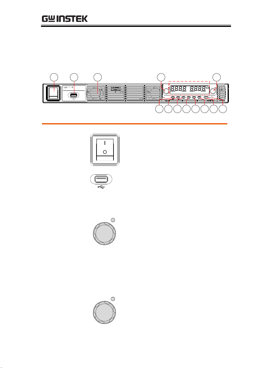
1.
Power Switch
Used to turn the power on/off.
2.
USB A Port
USB A port for data transfer,
loading test scripts etc.
3.
Air Inlet
Air inlet for cooling the inside of
the PSU series.
4.
Voltage Knob
Voltage
Used to set the voltage value or
select a parameter number in the
Function settings.
Display Area
The display area shows setting values, output
values and parameter settings. The function LEDs
below show the current status and mode of the
power supply. See page 14 for details.
5.
Current Knob
Current
Used to set the current value or
change the value of a Function
parameter.
Appearance
PSU Series Front Panel
11

PSU Series Quick Start Guide
6.
Lock/Local
Button
Lock/Local
Unlock
Used to lock all front panel
buttons other than the Output
Button or it switches to local
mode.
Unlock
Button
(Long push) Used to unlock the
front panel buttons.
7.
PROT Button
PROT
ALM_CLR
Used to set and display OVP, OCP
and UVL.
ALM_CLR
Button
(Long push) Used to release
protection functions that have
been activated.
8.
Function
Button
Function
M1
Used to configure the various
function.
M1 Button
(+Shift) Used to recall the M1
setup.
(+Shift and hold) Used to save the
current setup to M1.
9.
Test Button
TEST
M2
Used to run customized scripts for
testing.
M2 Button
(+Shift) Used to recall the M2
setup.
(+Shift and hold) Used to save the
current setup to M2.
10.
Set Button
SET
M3
Used to set and confirm the output
voltage and output current.
M3 Button
(+Shift) Used to recall the M3
setup.
(+Shift and hold) Used to save the
current setup to M3.
12

GETTING STARTED
11.
Shift Button
Shift
Used to enable the functions that
are written in blue characters
below the button.
12.
Output
Button
Output
Used to turn output on and off.
13.
Output ON
LED
Lights in green during output ON.
13

PSU Series Quick Start Guide
VSR LAN RMT ERR DLY ALM ISR M 1 M 2 M 3 RUN
C C
A
C V
V
VOLTAGE CURRENT
Display Area
14 1516 17
18 19 20 21 22 23 24
25
26 27 28
14.
Voltage
Meter
Displays the voltage or the parameter number of a
Function parameter.
15.
Current
Meter
Displays the current or the value of a Function
parameter.
16.
CV LED
Lights in green during constant voltage mode.
17.
CC LED
Lights in green during constant current mode.
18.
VSR LED
The voltage slew rate enable.
19.
LAN LED
Lights up when the LAN interface is connected.
20.
RMT LED
Lights in green during remote control.
21.
ERR LED
Lights in red when an error has occurred.
22.
DLY LED
The output on/off delay enable.
23.
ALM LED
Lights in red when a protection function has been
activated.
PSU Series Display and Operation Panel
14

GETTING STARTED
24.
ISR LED
The current slew rate enable.
25.
M1 LED
Lights in green when the memory value are being
recalled or saved.
26.
M2 LED
Lights in green when the memory value are being
recalled or saved.
27.
M3 LED
Lights in green when the memory value are being
recalled or saved.
28.
RUN LED
Auto sequence has been activated.
15

Rear Panel
L N
AC INPUT
DC OUTPUT
LANRS485 / 232
OUT IN
ANALOG PROGRAMMING
S LS SLSNC
REMOTE SENSE
100 240V
2000VA MAX.
AC
47 63Hz
234 15678
9 10
87654321
0 -5V / 0 - 10V
ISOLATED PROGRAMMING
87654321
4 -20mA
ISOLATED PROGRAMMING
1.
AC Input
L N
AC INPUT
Wire clamp connector.
2.
DC Output
Output terminals for 6V to 60V
models.
3.
USB
USB port for controlling the PSU
remotely.
4.
LAN
LAN
RS 485 / 232
Ethernet port for controlling the
PSU remotely.
PSU Series Quick Start Guide
16

GETTING STARTED
5.
Remote-IN
LAN
RS 485 / 232
Two different types of cables can
be used for RS232 or RS485-based
remote control.
PSU-232: RS232 cable with DB9
connector kit.
PSU-485: RS485 with DB9
connector kit.
6.
Remote-OUT
LAN
RS 485 / 232
RJ-45 connector that is used to
daisy chain power supplies with
the Remote-IN port to form a
communication bus.
PSU-485S: Serial link cable with
RJ-45 shielded connector.
7.
Analog
Control
ANALOG PROGRAMMING
External analog control connector.
8.
Remote
Sense
S LS SLSNC
REMOTE SENSE
Compensation of load wire drop.
9.
Option Slot
87654321
0 - 5V / 0 - 10V
ISOLATED PROGRAMMING
Blank sub-plate for standard units.
Isolated Analog connector for
units equipped with Isolated
Current and Voltage
Programming and Monitoring
option.
GPIB connector for units equipped
with IEEE programming option.
17

PSU Series Quick Start Guide
10.
Ground
Screw
Connector for grounding the output (two
positions, shown in red).
L N
AC INPUT
DC OUTPUT
100 240V
2000VA MAX.
AC
47 63Hz
18

OPERATION
Background
The PSU power supplies use a universal power
input that can be used with 100 and 240 Vac
systems. To connect or replace the power cord
(user supplied, specification below), use the
procedure below:
Warning
The following procedure should only be attempted
by competent persons.
Ensure the AC power cord is not connected to
power. Always allow the power supply to fully
discharge before disconnecting the AC power cord.
Recommended
Power Cord
Specifications
25A 250V, 3x12 AWG, outer diameter: 9-11mm,
rated 60 ºC min., 3m maximum length and
approved by the national safety standards for the
country of use.
The PSU has a number of power cord options
available. Please see the optional accessories on
page 8 for details.
Removal
1. Turn off the power switch and unplug the
power from the socket.
OPERATION
Set Up
Line Voltage Connection
19

PSU Series Quick Start Guide
2. Unscrew the power cord protective sheath.
3. Remove the 2 screws holding the power cord
cover and remove.
4. Remove the AC power cord wires with a flat
head screwdriver.
3
2
2-M3x6L
Pan Head Screw
GND: Green or
Green and Yellow
N: White or Blue
L: Black or Brown
4
Installation
1. Connect the AC power
cord wires to the AC input
terminals.
Black/Brown Line
(L)
White/Blue Neutral
(N)
Green /Green & Yellow
Ground ( )
AC INPUT
2000VA MAX.
47 63Hz
100 240VAC
NL
Ground
Line
Neutral
2. Make sure the sheath is
tightened to the lock nut.
3. Re-install the power cord
cover.
Screw on
locknut
20

Power Up
Steps
1. Connect the power cord to the
universal power input.
Page 19
2. Press the POWER switch on.
3. The power supply will show the Power On
settings (Pon) at start up. If no Power On
settings are configured, the PSU will recover
the state right before the power was last turned
OFF. If used for the first time, the default
settings will appear on the display.
VOLTAGE CURRENT
VSR LAN RMT ERR DLY ALM ISR M 1 M 2 M 3 RUN
C V C C
V A
Note
You may also configure how the PSU will behave
on startup by altering the Power On Configuration
settings, see the user manual for details.
Power Down
To turn the PSU power supply off, press the
power switch again (0 position). It may take a
few seconds for the power supply to fully turn
off.
CAUTION
The power supply takes around 8 seconds to fully
turn on and shutdown.
Do not turn the power on and off quickly. Please
wait for the display to fully turn off.
OPERATION
21

PSU Series Quick Start Guide
The OVP level and OCP level has a selectable
range that is based on the output voltage and
output current, respectively. The OVP and OCP
level is set to the highest level by default. The
actual selectable OVP and OCP range depends
on the PSU model.
When one of the protection measures are on,
ALM indicator is lit red on the front panel and
the type of alarm is also shown on the display.
The ALM_CLR button can be used to clear any
protection functions that have been tripped. By
default, the output will turn off when the OVP
or OCP protection levels are tripped.
The UVL will prevent you from setting a
voltage that is less than the UVL setting. The
UVL setting range is from 0% to 105% of the
rated output voltage.
VOLTAGE CURRENT
VSR LAN RMT ERR DLY ALM ISR M 1 M 2 M 3 RUN
C V C C
V A
Example: OVP alarm
Before setting the protection settings:
Ensure the load is not connected.
Ensure the output is turned off.
Note
You can use the Function settings (F-13 and F-14)
to apply limits to the voltage and current settings,
respectively. You can set limitations so that the
values do not exceed the set OVP and the set OCP
Basic Operation
Setting OVP/OCP/UVL Levels
22

OPERATION
level, and so that the values are not lower than the
set UVL trip point.
By using this feature, you can avoid turning the
output off by mistakenly setting the voltage or
current to a value that exceeds the set OVP or OCP
level or to a value that is lower than the set UVL
trip point.
If you have selected to limit the voltage setting (F-
14), you will no longer be able to set the output
voltage to a value that is above about 95% of the
OVP trip point or to a value that is lower than the
UVL trip point.
If you have selected to limit the current setting (F-
13), you will no longer be able to set the output
current to a value that is above about 95% of the
OCP trip point.
Steps
1. Press the PROT key. The PROT key
lights up.
PROT
2. The OVP protection function will be displayed
on the voltage display and the setting will be
displayed on the current display.
Protection
function
VOLTAGE CURRENT
VSR LAN RMT ERR DLY ALM ISR M 1 M 2 M 3 RUN
C V C C
V
Protection
setting
A
Choose a
Protection
Function
3. Turn the voltage knob to select a
protection function.
Voltage
Range
OVP, OCP, UVL
23

PSU Series Quick Start Guide
Setting the
Protection Level
4. Use the current knob to set the
protection level for the selected
function.
Current
Setting Range
PSU Model
OCP
OVP
UVL
6-200
5~220
0.6~6.6
0~6.3
12.5-120
5~132
1.25~13.75
0~13.12
20-76
5~83.6
2~22
0~21
40-38
3.8~41.8
4~44
0~42
60-25
2.5~27.5
5~66
0~63
5. Press PROT again to exit. The
PROT key light will turn off.
PROT
Clear
OVP/OCP/UVL
protection
The OVP, OCP or UVL protection
can be cleared after it has been
tripped by holding the ALM_CLR
button for 3 seconds.
PROT
ALM_CLR
24

OPERATION
Background
Before setting the power supply to C.V. mode,
ensure:
The output is off.
The load is connected.
Steps
1. Press the Function key. The
Function key will light up.
Function
2. The display will show the function (F-01) on the
voltage display and the setting for the function
in the current display.
VOLTAGE CURRENT
LAN RMT ERR DLY ALM ISR M 1 M 2 M 3 RUN
C V C C
V A
Function
number
Function
setting
3. Rotate the voltage knob to change
the F setting to F-03 (V-I Mode
Slew Rate Select).
Voltage
Set to C.V. Priority Mode
When setting the power supply to constant voltage mode, a current
limit must also be set to determine the crossover point. When the
current exceeds the crossover point, the mode switches to C.C.
mode. C.C. and C.V. mode have two selectable slew rates: High
Speed Priority and Slew Rate Priority. High Speed Priority will use
the fastest slew rate for the instrument while Slew Rate Priority will
use a user-configured slew rate.
25

PSU Series Quick Start Guide
4. Use the current knob to set the F-03
setting.
Set F-03 to 0 (CV High Speed
Priority) or 2 (CV Slew Rate
Priority).
Current
F-03
0 = CV High Speed Priority
2 = CV Slew Rate Priority
5. Press the Voltage knob to save the
configuration setting. ConF will be
displayed when it is configuring.
Voltage
Example
VOLTAGE CURRENT
VSR LAN RMT ERR DLY ALM ISR M 1 M 2 M 3 RUN
C V C C
V A
VSR indicator for CV Slew
Rate Priority (F-03=2)
6. If CV Slew Rate Priority was chosen as the
operating mode, set F-04 (Voltage Slew Rate
Up) and the F-05 (Voltage Slew Rate Down)
and save.
F-04 / F-05
0.001V~0.06V/msec (PSU 6-200)
0.001V~0.125V/msec (PSU 12.5-120)
0.001V~0.2V/msec (PSU 20-76)
0.001V~0.4V/msec (PSU 40-38)
0.001V~0.6V/msec (PSU 60-25)
7. Press the Function key again to exit
the configuration settings. The
function key light will turn off.
Function
8. Use the Current knob to set the
current limit (crossover point).
Current
26

OPERATION
9. Use the Voltage knob to set the
voltage.
Voltage
Note
Notice the Set key becomes illuminated when
setting the current or voltage. If the voltage or
current knobs are unresponsive, press the Set key
first.
10. Press the Output key. The
Output ON LED becomes
lit.
Output
Example
CV will become
illuminated (center)
AV
VOLTAGE CURRENT
VSR LAN RMT ERR DLY ALM ISR M 1 M 2 M 3 RUN
C V C C
Note
Only the voltage level can be altered when the
output is on. The current level can only be changed
by pressing the Set key.
For more information on the Normal Function
Settings, see the user manual.
27

PSU Series Quick Start Guide
Background
Before setting the power supply to C.C. mode,
ensure:
The output is off.
The load is connected.
Steps
1. Press the Function key. The
Function key will light up.
Function
2. The display will show the function (F-01) on the
voltage display and the setting for the function
in the current display.
VOLTAGE CURRENT
LAN RMT ERR DLY ALM ISR M 1 M 2 M 3 RUN
C V C C
V A
Function
number
Function
setting
3. Rotate the voltage knob to change
the F setting to F-03 (V-I Mode
Slew Rate Select).
Voltage
Set to C.C. Priority Mode
When setting the power supply to constant current mode, a voltage
limit must also be set to determine the crossover point. When the
voltage exceeds the crossover point, the mode switches to C.V.
mode. C.C. and C.V. mode have two selectable slew rates: High
Speed Priority and Slew Rate Priority. High Speed Priority will use
the fastest slew rate for the instrument while Slew Rate Priority will
use a user-configured slew rate.
28

OPERATION
4. Use the current knob to set the F-03
setting.
Set F-03 to 1 (CC High Speed
Priority) or 3 (CC Slew Rate
Priority) and save.
Current
F-03
1 = CC High Speed Priority
3 = CC Slew Rate Priority
5. Press the Voltage knob to save the
configuration setting. ConF will be
displayed when it is configuring.
Voltage
Example
VOLTAGE CURRENT
LAN RMT ERR DLY ALM ISR M 1 M 2 M 3 RUN
C V C C
V A
ISR indicator for CC Slew
Rate Priority (F-03=3)
6. If CC Slew Rate Priority was chosen as the
operating mode, set F-06 (Current Slew Rate
Up) and F-07 (Current Slew Rate Down) and
save.
F-06 / F-07
0.001A~2A / msec (PSU 6-200)
0.001A~1.2A / msec (PSU 12.5-120)
0.001A~0.76A / msec (PSU 20-76)
0.001A~0.38A / msec (PSU 40-38)
0.001A~0.25A / msec (PSU 60-25)
7. Press the Function key again to exit
the configuration settings. The
function key light will turn off.
Function
8. Use the Voltage knob to set the
voltage limit (crossover point).
Voltage
29

PSU Series Quick Start Guide
9. Use the Current knob to set the
current.
Current
Note
Notice the Set key becomes illuminated when
setting the current or voltage. If the voltage or
current knobs are unresponsive, press the Set key
first.
10. Press the Output key. The
Output key becomes
illuminated.
Output
Example
CC will become
illuminated (right)
AV
VOLTAGE CURRENT
VSR LAN RMT ERR DLY ALM ISR M 1 M 2 M 3 RUN
C V C C
Note
Only the current level can be altered when the
output is on. The voltage level can only be changed
by pressing the Set key.
For more information on the Normal Function
Settings, see the user manual.
30

APPENDIX
423.0
43.6
447.2
501.9
Lock/Local PROT Function Test Set
Output
Unlock ALM_CLR M 1 M 2 M 3
Shift
: Long Push
VSR LAN RMT ERR DLY ALM ISR M 1 M 2 M 3 RUN
C CAC V
V
VOLTAGE CURRENT
DC Power Supply
0 - 40V / 0 - 38A
Voltage Current
Units = mm
APPENDIX
PSU Dimensions
PSU 6-200, PSU 12.5-120, PSU 20-76, PSU 40-38, PSU 60-25
31

PSU Series Quick Start Guide
Declaration of Conformity
We
GOOD WILL INSTRUMENT CO., LTD.
declare that the below mentioned product
Type of Product: Programmable DC Power Supply
Model Number: PSU 6-200, PSU 12.5-120, PSU 20-76, PSU 40-38, PSU 60-25
are herewith confirmed to comply with the requirements set out in the
Council Directive on the Approximation of the Law of Member States
relating to Electromagnetic Compatibility (2014/30/EU), Low Voltage
Directive (2014/35/EU), WEEE (2012/19/EU) and RoHS (2011/65/EU).
For the evaluation regarding the Electromagnetic Compatibility and Low
Voltage Directive, the following standards were applied:
◎ EMC
EN 61326-1:
EN 61326-2-1:
Conducted & Radiated Emission
EN 55011: 2009+A1:2010
Current Harmonics
EN 61000-3-2: 2006+A1: 2009+A2: 2009
Voltage Fluctuations
EN 61000-3-3: 2008
Electrostatic Discharge
EN 61000-4-2: 2009
Radiated Immunity
EN 61000-4-3: 2006+A1:2008+A2:2010
Low Voltage Equipment Directive 2014/35/EU
Safety Requirements
Electrical equipment for measurement, control and
laboratory use –– EMC requirements (2013)
Electrical Fast Transients
EN 61000-4-4: 2012
Surge Immunity
EN 61000-4-5: 2006
Conducted Susceptibility
EN 61000-4-6: 2009
Power Frequency Magnetic Field
EN 61000-4-8: 2010
Voltage Dip/ Interruption
EN 61000-4-11: 2004
EN 61010-1: 2010
GOODWILL INSTRUMENT CO., LTD.
No. 7-1, Jhongsing Road, Tucheng District, New Taipei City 236, Taiwan
Tel: +886-2-2268-0389 Fax: +886-2-2268-0639
Web: http://www.gwinstek.com Email: marketing@goodwill.com.tw
GOODWILL INSTRUMENT (SUZHOU) CO., LTD.
No. 521, Zhujiang Road, Snd, Suzhou Jiansu 215011, China
Tel: +86-512-6661-7177 Fax: +86-512-6661-7277
Web: http://www.instek.com.cn Email: marketing@instek.com.cn
GOODWILL INSTRUMENT EURO B.V.
De Run 5427A, 5504DG Veldhoven, The Netherlands
Tel: +31-(0)40-2557790 Fax: +31-(0)40-2541194
Email: sales@gw-instek.eu
32
 Loading...