


Muti-Range Bench-Top DC Power
Supply
PSB-2000 series
User Manual
GW INSTEK PART NO. 82SB-28H00E01
ISO-9001 CERTIFIED MANUFACTURER

Copyright Statement
This manual contains proprietary information, which is protected by
copyright. All rights are reserved. No part of this manual may be
photocopied, reproduced or translated to another language without
prior written consent of Good Will company.
The information in this manual was correct at the time of printing.
However, Good Will continues to improve products and reserves the
rights to change specification, equipment, and maintenance
procedures at any time without notice.
Good Will Instrument Co., Ltd.
No. 7-1, Jhongsing Rd., Tucheng Dist., New Taipei City 236, Taiwan.

Table of Contents
Table of Contents
SAFETY INSTRUCTIONS ................................................... 5
GETTING STARTED ........................................................... 9
PSB 2000 Series Overview .............................. 10
Appearance .................................................... 17
OPERATION .................................................................... 32
Connecting the AC Power Cable ...................... 32
Connecting the Load to the Output Terminals 32
Operation Ranges (PSB-2400L, 2800L, 2400L2,
2800LS) .......................................................... 40
Operation Ranges (PSB-2400H, 2800H) ......... 41
Various Settings ............................................. 42
Menu Key Functions ....................................... 49
Voltage Sense ................................................. 73
External Control Functions ............................. 75
Using the Sequence Function ......................... 85
OTHER FUNCTIONS ....................................................... 88
Display in Alarm Status .................................. 88
Frame Link Controlled Paralle l Operation
(excluding PSB-2400L2) .................................. 90
Frame Link Controlled Series Operation
(excluding PSB-2400L2, PSB-H series) ........... 92
Power Extension using PSB-2800LS (Parallel
Connection Only) ........................................... 93
Using the PSB-007 Extension kits ................... 94
EXTERNAL CONTROL ..................................................... 98
Remote Control .............................................. 98
Interface Connectors ...................................... 99
3

PSB-2000 Series User Manual
PSB-001 Specifications (optional) .................. 99
PSB-002 Specifications (standard) ................ 100
Connection Methods .................................... 101
Connection Cables ........................................ 103
Address Setting ............................................ 104
Using the Interface Boards ........................... 107
Communication Commands ......................... 110
Registers ...................................................... 132
APPENDIX ..................................................................... 142
Trouble Shooting .......................................... 142
Maintenance ................................................. 144
Dimensions .................................................. 146
Specifications ............................................... 149
Declaration of Conformity ............................ 160
4
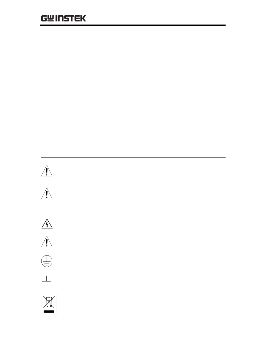
SAFETY INSTRUCTIONS
WARNING
Warning: Identifies conditions or practices that
could result in injury or loss of life.
CAUTION
Caution: Identifies conditions or practices that
could result in damage to the PSB or to other
properties.
DANGER High Voltage
Attention Refer to the Manual
Protective Conductor Terminal
Earth (ground) Terminal
Do not dispose electronic equipment as unsorted
municipal waste. Please use a separate collection
facility or contact the supplier from which this
instrument was purchased.
SAFETY INSTRUCTIONS
This chapter contains important safety
instructions that you must follow during
operation and storage. Read the following before
any operation to insure your safety and to keep
the instrument in the best possible condition.
Safety Symbols
These symbols may appear in the manual or on the instrument.
5
PSB-2000 Series User Manual
General
Guideline
CAUTION
Do not place any heavy object on the unit.
Avoid severe impact or rough handling that
leads to damaging the unit.
Do not discharge static electricity to the unit.
Do not block the cooling fan opening.
Do not perform measurements on circuits that
are directly connected to mains power.
Do not disassemble the PSB unless you are
qualified.
(Measurement categories) EN 61010-1:2001 specifies the
measurement categories and their requirements as follows. The
PSB-2000 falls under category I.
Measurement category IV is for measurement performed at the
source of low-voltage installation.
Measurement category III is for measurement performed in the
building installation.
Measurement category II is for measurement performed on the
circuits directly connected to the low voltage installation.
Measurement category I is for measurements performed on
circuits not directly connected to Mains.
Power Supply
WARNING
AC Input voltage range: 100VAC~240VAC,
1300VA Max
Frequency: 50Hz/60Hz
To avoid electrical shock connect the protective
grounding conductor of the AC power cord to
an earth ground.
Safety Guidelines
6

SAFETY INSTRUCTIONS
Cleaning the
power supply
Disconnect the power cord before cleaning the
oscilloscope.
Use a soft cloth dampened in a solution of mild
detergent and water. Do not spray any liquid
into the oscilloscope.
Do not use chemicals containing harsh products
such as benzene, toluene, xylene, and acetone.
Operation
Environment
Location: Indoor, no direct sunlight, dust free,
almost non-conductive pollution (Note below)
Relative Humidity: 30% to 80% (no dew or
condensation)
Altitude: < 2000m
Temperature: 0°C to 40°C
(Pollution Degree) EN 61010-1:2001 specifies pollution degrees
and their requirements as follows. The PSB falls under degree 2.
Pollution refers to “addition of foreign matter, solid, liquid, or
gaseous (ionized gases), that may produce a reduction of dielectric
strength or surface resistivity”.
Pollution degree 1: No pollution or only dry, non-conductive
pollution occurs. The pollution has no influence.
Pollution degree 2: Normally only non-conductive pollution
occurs. Occasionally, however, a temporary conductivity caused
by condensation must be expected.
Pollution degree 3: Conductive pollution occurs, or dry, non-
conductive pollution occurs which becomes conductive due to
condensation which is expected. In such conditions, equipment
is normally protected against exposure to direct sunlight,
precipitation, and full wind pressure, but neither temperature
nor humidity is controlled.
Storage
environment
Location: Indoor
Relative Humidity: 30% to 70% (no dew or
conensation)
Temperature: -20°C to 70°C
7
PSB-2000 Series User Manual
Green/ Yellow:
Earth
Blue:
Neutral
Brown:
Live (Phase)
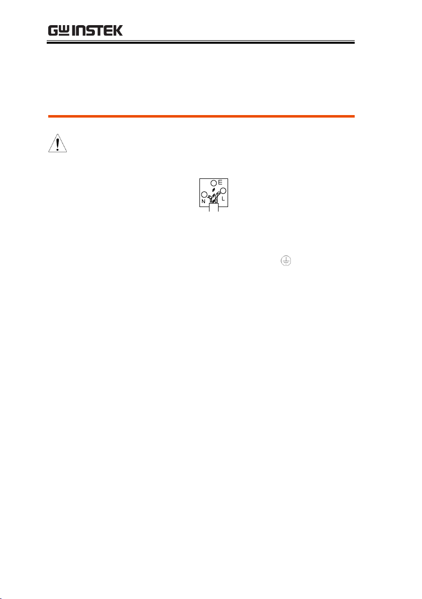
Power cord for the United Kingdom
When using the power supply in the United Kingdom, make sure
the power cord meets the following safety instructions.
NOTE: This lead/appliance must only be wired by competent persons
WARNING: THIS APPLIANCE MUST BE EARTHED
IMPORTANT: The wires in this lead are coloured in accordance with the
following code:
As the colours of the wires in main leads may not correspond with the
coloured marking identified in your plug/appliance, proceed as follows:
The wire which is coloured Green & Yellow must be connected to the Earth
terminal marked with either the letter E, the earth symbol or coloured
Green/Green & Yellow.
The wire which is coloured Blue must be connected to the terminal which
is marked with the letter N or coloured Blue or Black.
The wire which is coloured Brown must be connected to the terminal
marked with the letter L or P or coloured Brown or Red.
If in doubt, consult the instructions provided with the equipment or
contact the supplier.
This cable/appliance should be protected by a suitably rated and approved
HBC mains fuse: refer to the rating information on the equipment and/or
user instructions for details. As a guide, a cable of 0.75mm2 should be
protected by a 3A or 5A fuse. Larger conductors would normally require
13A types, depending on the connection method used.
Any exposed wiring from a cable, plug or connection that is engaged in a
live socket is extremely hazardous. If a cable or plug is deemed hazardous,
turn off the mains power and remove the cable, any fuses and fuse
assemblies. All hazardous wiring must be immediately destroyed and
replaced in accordance to the above standard.
8

GETTING STARTED
GETTING STARTED
The PSB series are variable output, highperformance, regulated, switching DC power
supplies. They incorporate a high-frequency
current suppression circuit and accept input
voltages rated from AC100V to 240V without the
need to switch inputs. The offer a wide voltage
and current range within their maximum rated
power envelope. They also have a variable
constant power function. They have standard
features such as voltage and current settings, an
output on/off switch, monitor outputs and other
functions via external connectors. The chasis is
smaller overall than traditional power supplies to
reduce the total work area. The dual channel
model and the booster unit extend the series to
cover a wider range of applications. The PSB series
are also able to execute sequence programs that
are written using the optional interface boards.
The optional interface boards also allow you to
control the PSB series remotely from a PC using
GPIB, RS232C or USB.
9

PSB-2000 Series User Manual
Product name
Voltage range
Current range
Power range
PSB-2400H
0V to 800V
0A to 3A
0W to 400W
PSB-2800H
0V to 800V
0A to 6A
0W to 800W
PSB-2400L
0V to 80V
0A to 40A
10W to 400W
PSB-2800L
0V to 80V
0A to 80A
10W to 800W
PSB-2400L2 (Dual
channel type)
0V to 80V
×2CH
0A to 40A
×2CH
10W to 400W
×2CH
PSB-2800LS
(Booster unit)
0V to 80V
0A to 80A
10W to 800W
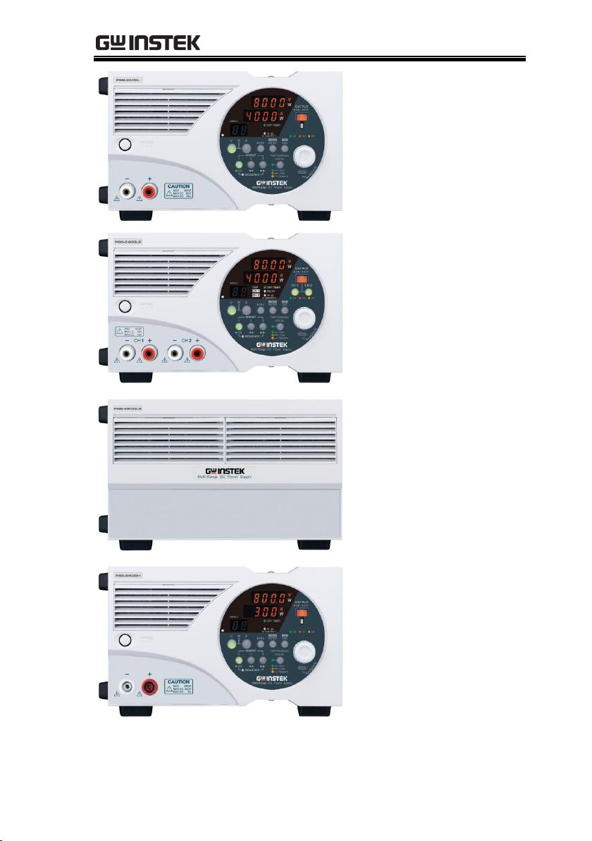
PSB 2000 Series Overview
Series line up
10
GETTING STARTED
■ 400W Type
PSB-2400L
■ 800W Type
PSB-2800L
■ 400W×2-Channel Type
PSB-2400L2
■ 800W Type
Booster unit
PSB-2800LS
■ 400W Type
PSB-2400H
■ 800W Type
PSB-2800H
11

PSB-2000 Series User Manual
Multi-Range
Output
Capable of a wide-range of voltage and current
settings within the rated power envelope.
Constant-Power
Control
Provides constant-power (CP) control in addition to
constant-voltage (CV) and constant-current (CC)
controls.
Power Factor
Correction Circuit
A built-in power factor correction circuit ensures
compatibility to a wide AC input voltage range from
AC100V to 240V without the need to use a switch. It
also suppresses harmonic current.
Rotatable Front
Panel Controls
The front panel can be rotated by 90 degrees to allow
the unit to be operated horizontally or vertically.
Output Off Timer
Function
Turns the output off automatically after a preset
amount of time has elapsed. This can be used to
prevent the output from being left on inadvertently or
to prevent over-charging.
Sequence (SEQ)
Function
The Sequence function executes data read from a PC
through one of the optional interface boards (PSB001 and PSB-002). There are two operation modes for
the sequence function: Manual mode (for step by
step execution) and automatic mode (for automatic
execution of up to 99 steps and 999 cycles).
Protective
Functions
The power supplies have a number of protection
functions. OVP, OCP and OHP. OVP and OCP
protection can be set on the front panel.
Preset Functions
(Three Settings)
Pressing a preset key directly selects a preset setting,
which is set in advance.
Main Features
12

GETTING STARTED
Single Unit
Control of
Parallel/Series
Operation
The PSB-L series uses a single power supply unit
(acting as the master unit) to control all connected
slave units for series or parallel operation. In parallel,
up to 4 units can be controlled (including the master)
to increase the total power. In series, a maximum of 2
units (including the master) can be used.
External Control
Function
The external control function allows external voltage
and restistance-based control, voltage and current
monitoring, output on/off control, alarm output and
CV/CC status output.
Interface Boards
There are two optional interface boards for remote
control.
PSB-001: GPIB and local bus board.
PSB-002: RS-232C, USB and local bus board.
Note also that one of these options must be used to
program sequences for the PSB-L series. See page 85
for further details.
Dual Channel
Model
(PSB-2400L2)
Equipped with two 400W output channels for a
wide variety of applications.
Delay (DLY)
Function:
(PSB-2400L2
Only)
The delay function introduces a switching delay
between channel 1 and 2. The delay function can set
a rising delay (the time to turn on) and a falling delay
(the time to turn off).
Tracking
Function:
(PSB-2400L2
Only)
The channel 2 setting is made equal to that of
channel 1 when the tracking function is activated.
Thereafter, both channels change synchronously.
13
PSB-2000 Series User Manual
Model Number
Description
PSB-001
GPIB Control Board. Includes GRJ-1101 modular
cables. For further details, see page 99.
PSB-002
RS-232C/USB Control Board. Includes GRJ-1101
modular cables. For further details, see page 100.
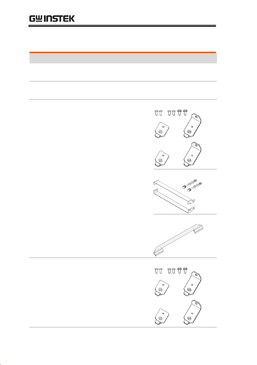
PSB-003
Parallel Connection Kit for
Horizontal Installation.
Kit includes: PSB-007 Joint
kit, Horizontal bus bar x2,
PSB-005 x1.
PSB-007 Joint Kit
Horizontal Bus Bar
PSB-005
PSB-004
Parallel Connection Kit for
Vertical Installation.
Kit includes: PSB-007 Joint
kit, Verical bus bar x2, PSB005 x1.
PSB-007 Joint Kit
Accessories
14
GETTING STARTED
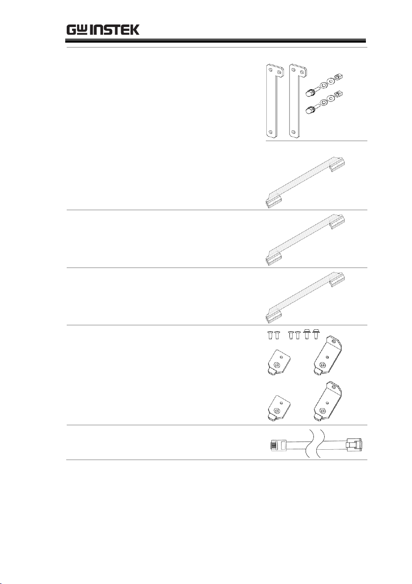
Vertical Bus Bar
PSB-005
PSB-005
Parallel Connection Signal
Cable
PSB-006
Serial Connection Signal
Cable
PSB-007
Joint Kit:
Includes 4 joining plates, 4X
M3x6 screws, 2X M3x8
screws.
GRJ-1101
Modular Cables: 500mm
6P6C RJ11 (local bus cables)
15

PSB-2000 Series User Manual
Model Number
Description
User Manual CD x 1
AC power cable x 1
Screws for output terminals on rear panel
Protection covers for output terminals on rear panel
Protection caps for output terminals on the front
panel
External control connector (26-pin)
GND cable
Standard Accessories
16
GETTING STARTED
1 5 6 7 8 9 10 11 12 13
2 3 4 14 15 16 17 18 19 20 21 22
POWER
CHECK
ENTER
REMOTE
FAST
LOCK
Hi -
W
V A
CV
MENU
SEQUENCE
PRESET
321
FAST/LOCK(3s)
/LOCAL
OUTPUT
OFF TIMER
DISP
ESCMENU
W
CC CP
A
W
R
O
T
A
T
E
V
W
Multi- Range DC Power Supply
DELAY
CH 2
CH 2
CH 1
DISP
CH 1
(L Type ONLY)
CH 1
MAX 400W
MAX DC 80V
MAX DC 40A
CH 2
PSB- 2400L 2
ON / OFF
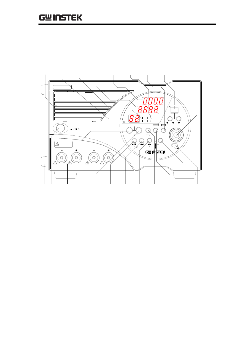
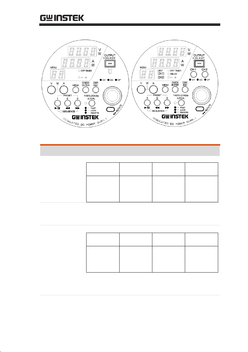
Appearance
Front Panel (PSB-2400L2 shown)
17
PSB-2000 Series User Manual
1 5 6 7 8 9 10 11 12 13
2 3 4 14 15 16 17 18 19 20 21 22
POWER
CAUTION
MAX 400W
MAX DC 800V
MAX DC 3A
PSB - 2400H
CHECK
ENTER
REMOTE
FAST
LOCK
Hi -
W
V A
CV
MENU
SEQUENCE
PRESET
321
FAST/LOCK(3s)
/LOCAL
OUTPUT
OFF TIMER
DISP
ESCMENU
W
CC CP
A
W
R
O
T
A
T
E
V
(
L Type ONLY
)
W
Regulated DC Power Supply
ON / OFF
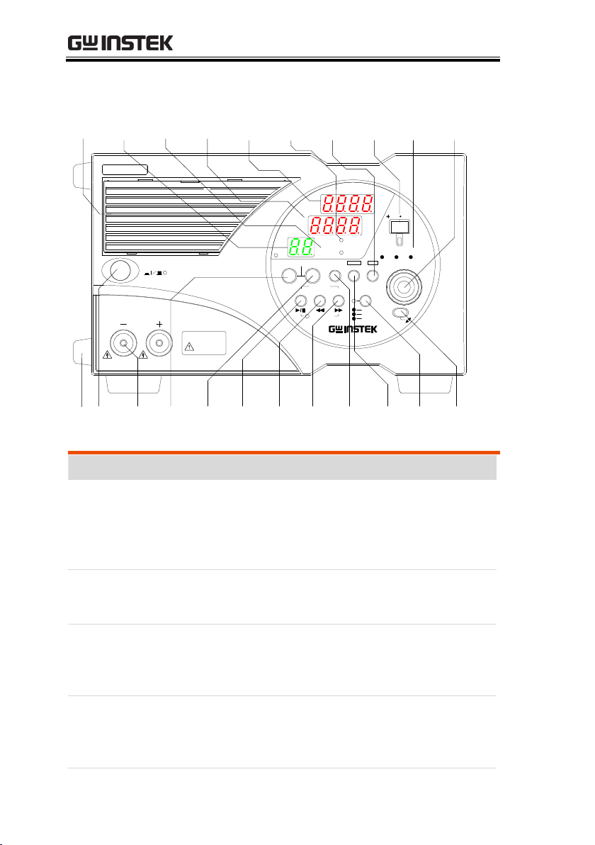
Item
Description
1
Front grill
This is a ventilation grill for for cooling the
internal circuits. It is detachable and has a dust
filter inside. Clean the filter periodically. See page
142.
2
Rubber feet
Detachable. If the unit is mounted in a rack and
the feet are not needed, they may be removed.
3
POWER
ON/OFF
switch
Depress the switch to the (I) position to turn on
the power supply unit. Press it again to turn off
the unit.
4
Front output
terminals
Output is supplied through these terminals. The
maximum current is 40A(2400L, 2800L, 2400L2,
2800LS), 3A(2400H) or 6A(2800H).
Front Panel (PSB-2400H shown)
18
GETTING STARTED
PSB-2400L, PSB-2800L
PSB-2400H, PSB-2800H
PSB- 2400L2
Type
Description
5
Address no.,
Step no.,
cycle no.,
Menu no.
Normal
operation
Sequence
operation
Menu
Tracking
Not
displayed.
Number of
steps or
cycles is
displayed.
Menu No. is
displayed.
“Ab” is
displayed.
6
Channel
LEDs
The LED of the selected channel is lit. Both LEDs
are lit when the tracking function is activated.
7
Current LED
(7-segment)
Normal
operation
Sequence
operation
Menu
Alarm
Current or
power is
displayed.
Step No. is
displayed.
Set item is
displayed.
OVP, OCP,
HARD or
OHP is
displayed.
The ―W‖ LED on the right of the 7-segment LED
is lit in the power display state.
Panel Operation Unit
19
PSB-2000 Series User Manual
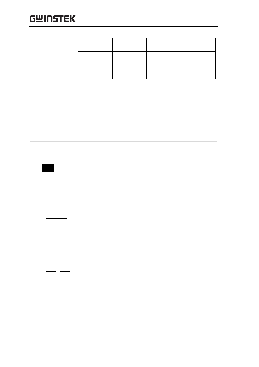
8
Voltage LED
(7-segment)
Normal
operation
Sequence
operation
Menu
Alarm
Voltage or
power is
displayed.
Cycle No. is
displayed.
Set parameter
is displayed.
OVP, OCP,
HARD or
OHP is
displayed.
The ―W‖ LED on the right of the 7-segment LED
is lit in the power display state.
9
Function
LEDs
These LEDs display the On/Off state of the OFF
TIMER, DELAY or HiΩ functions. The LED is lit
green when the corresponding function is
activated.
10
ESC/DISP
key (ESC /
DISP)
Changes the channel display, sequence operation
display (i.e., step No. and cycle No.), remaining
time for the off-timer and other displays. When
the menu is displayed, pressing it exits the
function selection mode and returns to the normal
mode.
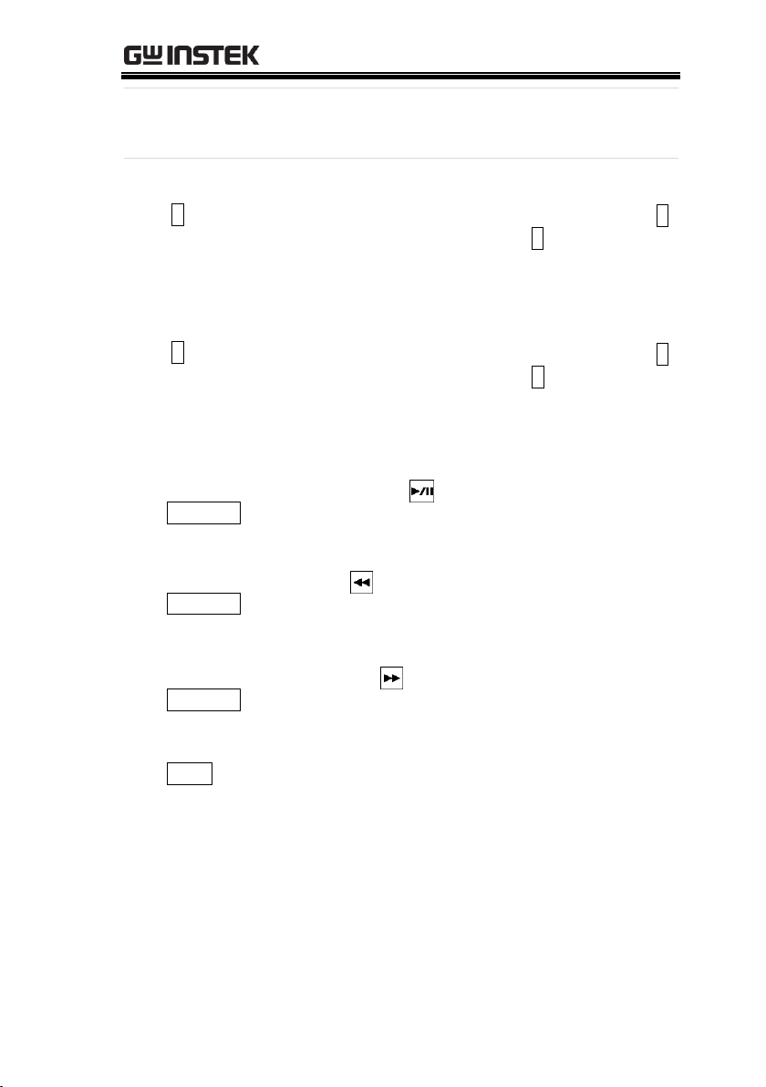
11
OUTPUT key
(red)
( OUTPUT )
This key turns on or off the output. The LED is lit
when the output is turned on.
12
CH1 and
CH2 keys
(red, green,
orange)
( CH1 , CH2 )
These keys turn on or off the channel outputs. The
color of the corresponding LED indicates the
output mode.
Green: CV mode.
Red: CC mode.
Orange: CP mode.
The CH1 and CH2 keys are only available for the
PSB-2400L2 only. The PSB-2400L and PSB-2800L
have single LEDs only.
20
GETTING STARTED
13
Rotary
encoder
Used to select the functions and change the
values.
14
V key (green)
( V )
Used for setting the voltage. Press the key and
rotate the encoder to change the set value. If the A
key is pressed while holding the V key, both LEDs
are lit and the Current LED enters the power
display mode.
15
A key (green)
( A )
Used for setting the current. Press the key and
rotate the encoder to change the set value. If the V
key is pressed while holding the A key, both LEDs
are lit and the Voltage LED enters the power
display mode.
16
PRESET 1
key (green)
(PRESET 1)
Reads out data stored in PRESET 1. Serves as a
start/pause key ( ) in the sequence mode.
17
PRESET 2
key (green)
(PRESET 2 )
Reads out data stored in PRESET 2. Serves as a
back key ( ) to a skip to previous step number
in the sequence mode.
18
PRESET 3
key (green)
(PRESET 3 )
Reads out data stored in PRESET 3. Serves as a
forward key ( ) to skip to the next step number
in the sequence mode.
19
MENU key
(MENU)
Used for setting and selecting various functions.
21
PSB-2000 Series User Manual
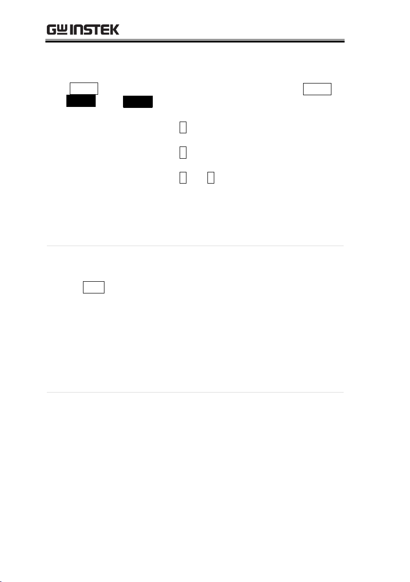
20
ENTER/
CHECK Key
(ENTER /
CHECK)
Alternates the operation (and display) between
the output value and the set value.
When the output is on, every press of the ENTER/
CHECK key alternates the display between the
output value and set value.
・ When the V key is lit The voltage setting is
enabled.
・ When the A key is lit The current setting is
enabled.
・ When the V and A keys are lit the power
setting is
enabled.
When the menu is displayed, press this key to
validate functions and values in the menu.
21
FAST/LOCK
(3s)/LOCAL
key(FAST )
Changes the resolution of the voltage, current or
power settings, locks panel operation, or switches
the remote mode into the local mode. The color of
the LED indicates the current status.
FAST (green): The setting resolution is 1V,
1A or 100W.
LOCK (3s) (red): Operations on the front
panel are disabled.
REMOTE (orange): Lit during communication
through the optional
interface boards.
22
ROTATE key
The operating panel of the PSB-2000 series can be
rotated 90 degrees so that the unit can be used in
the horizontal or vertical position. Hold the
encoder and rotate the panel operation unit while
holding the key.
22
GETTING STARTED
PSB-002
LOCAL BUS
I I IUSB
J3
EXT CONT
▲
J2
△
AC INPUT
1
2 26
25
CH 2
CH 1
J1
MADE IN TAIWAN
~100V-240V
50Hz / 60Hz
650 VA MAX
MAX 400W
MAX DC 80V
MAX DC 40A
!
OUTPUT
DC
MAX 400W
MAX DC 80V
MAX DC 40A
!
OUTPUT
DC
!
23 24 25 26 27 28 29 30 31
23 24 25 26 27 28 29 30 31
PSB-002
LOCAL BUS
I I IUSB
2
1
EXT CONT
J3
26
J1 J2
AC INPUT
△
25
MADE IN TAIWAN
DC
OUTPUT
!
MAX DC 3A
MAX DC 800V
MAX 400W
+ +S
CAUTION
-S -
!
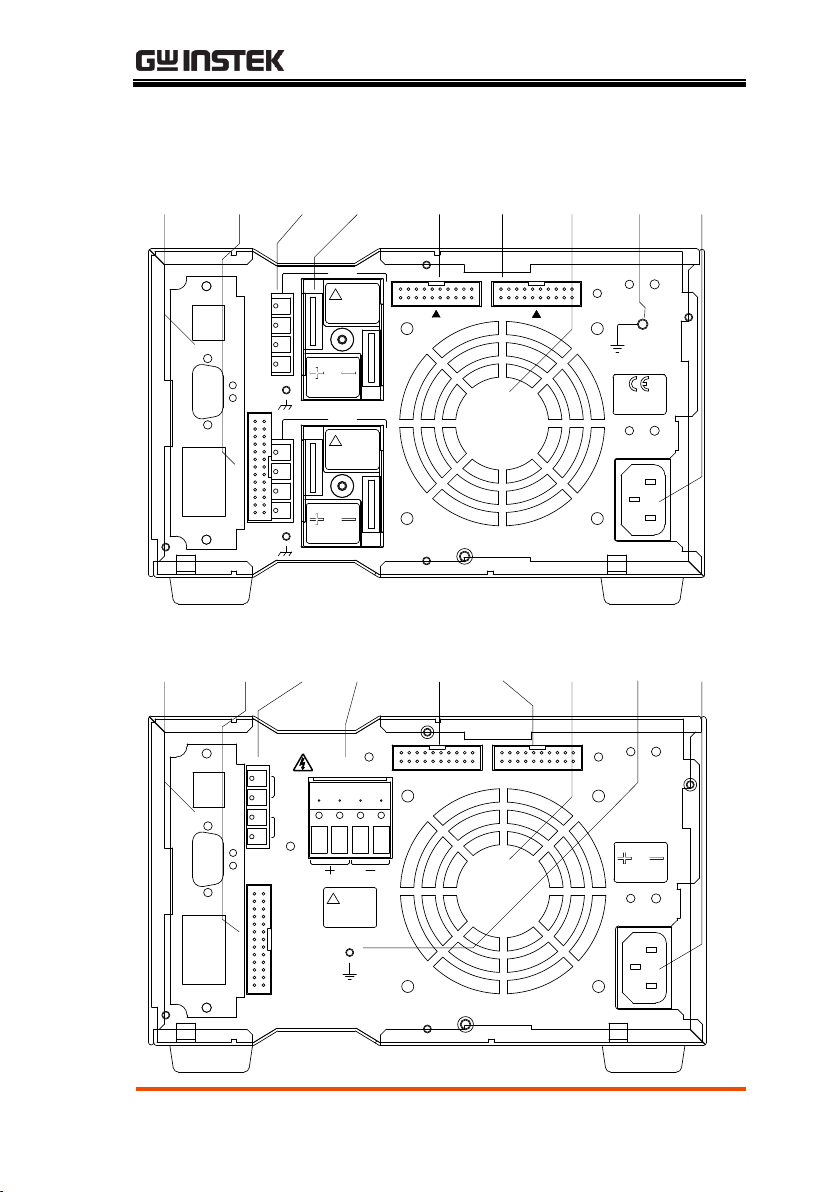
Rear Panel (PSB-2400L2 shown)
23

PSB-2000 Series User Manual
Description
23
Optional
Interface
board slot
The optional interface board slot is used to install
the optional PSB-001 board for the GPIB interface.
The product is supplied with the USB/RS-232C
option as standard.
24
J3 external
control
connector
The external control connector is used to control
or monitor a number of different parameters
using external components. The pin assignment
of this connector can be found on page 26(40A
models) 30(3A/6A models).
25
Sensing
terminals
The sensing terminals are used to change the
sensing point. These terminals are short-circuited
before shipment to select internal sensing.
26
Rear output
terminals
The Output of the PSB-2000 series power supply
unit is also output through these terminals. The
type of rear panel output terminal varies
depending on the model. The PSB-2400H and
PSB-2800H use pin terminals and the PSB-L
models use crimp style voltages designed to
accommodate higher current.
For the PSB-2400L2 (dual channel model), the
channel 1 terminal block is in the upper part
(CH1) and the channel 2 terminal block is in the
lower part (CH2) of the rear panel when the unit
is viewed from the back. On each terminal block,
the positive (+) terminal is on the left and the
negative (-) terminal is on the right when the
unit is viewed from the back. Connect either
output terminal to the screw marked with the
ground signal if it needs to be grounded with
the chassis.
24

GETTING STARTED
27
J1 control
signal input
connector
This connector is used for parallel and serial
control for master/slave operation. The optional
frame link cables must be used with this
connector.
28
J2 control
signal output
connector
This connector is used for parallel and serial
control for master/slave operation. The optional
framelink cables must be used with this
connector.
29
Exhaust Grill
Air taken into the unit from the front is blown out
through this grill. Leave a gap of a least 30cm or
more behind the rear panel for good ventilation.
If there is an object obstructing the rear panel, the
temperature inside the power supply unit may
rise excessively.
30
Functional
ground
terminal
The unit can be grounded using this terminal
31
AC INPUT
Connect the AC power cable supplied with the
unit with this plug receptacle and supply AC
power to the unit.
25

PSB-2000 Series User Manual
Pin No.
Signal name
Function
1
CH2 STATUS COM
(COM for 2, 3 & 4)
COM for pins 2, 3 and 4.
2
CH2 ALARM OUT
Open collector output. When the alarm
is output for channel 2 then this pin is
pulled low.
3
CH2 EXT CC
STATUS OUT
Open collector output. Set to the low
level when channel 2 is in CC mode.
4
CH2 EXT CV
STATUS OUT
Open collector output. Set to the low
level when channel 2 is in CV mode.
5
CH2 EXT CV
CONTROL IN
Constant-voltage control input pin for
channel 2.
In the external voltage control mode, an
external voltage of 0V to 10V can be
used to control the output voltage from
~0V to the rated output voltage.
In the external resistance control mode,
an external resistance of 0kΩ to 10kΩ
can be used to control the output
voltage from ~0V to the rated output
voltage.
Pin assignment of the J3 External Control Connector
(PSB-2400L, 2800L, 2400L2, 2800LS)
26

GETTING STARTED
6
CH2 EXT CC
CONTROL IN
Constant-current control input pin for
channel 2.
In the external voltage control mode, an
external voltage of 0V to 10V can be
used to control the ouput current from
~0A to the rated output current.
In the external resistance control mode,
an external reistance of 0kΩ to 10kΩ can
be used to control the output current
from ~0A to the rated output current.
7
CH2 COM
COM pin for channel 2.
Connected to the negative output
terminal of channel 2.
8
CH2 EXT V MON
OUT
Output voltage monitor pin for channel
2.
Outputs a voltage of approximately 0V
to 10V to represent 0V to the rated
output voltage.
9
CH2 EXT A MON
OUT
Output current monitor pin for channel
2.
Outputs a voltage of approximately 0V
to 10V to represent 0A to the rated
output current.
10
CH2 COM
COM pin for channel 2. Connected with
the negative output terminal of channel
2.
11
CH2 EXT ALARM
IN
Causes the alarm state to be triggered
when short-circuited with the CH2
COM pin.
12
CH2 EXT OUTPUT
IN
This pin turns the CH2 output on when
it is shorted to the CH2 COM pin.
27

PSB-2000 Series User Manual
13
CH2 COM
COM pin for channel 2. Connected with
the negative output terminal of channel
2.
14
CH1 EXT CV
CONTROL IN
Constant-voltage control input pin for
the channel 1.
In the external voltage control mode, an
external voltage of 0V to 10V can be
used to control the output voltage from
~0V to the rated output voltage.
In the external resistance control mode,
an external resistance of 0kΩ to 10kΩ
can be used to control the output
voltage from ~0V to the rated output
voltage.
15
CH1 EXT CC
CONTROL IN
Constant-current control input pin for
channel 1.
In the external voltage control mode, an
external voltage of 0V to 10V can be
used to control the ouput current from
~0A to the rated output current.
In the external resistance control mode,
an external reistance of 0kΩ to 10kΩ can
be used to control the output current
from ~0A to the rated output current.
16
CH1 COM
COM pin for channel 1.
Connected with the negative output
terminal of channel 1.
17
CH1 EXT V MON
OUT
Output voltage monitor pin for channel
1.
Outputs approx. 0V to 10V to represent
0V to the rated output voltage.
28

GETTING STARTED
18
CH1 EXT A MON
OUT
Output current monitor pin for channel
1.
Outputs approx. 0V to 10V to represent
0 to the rated output current.
19
CH1 COM
COM pin for channel 1.
Connected with the negative output
terminal of channel 1.
20
CH1 EXT ALARM
IN
Causes the alarm state to be triggered
when short-circuited with the CH1
COM pin.
21
CH1 EXT OUTPUT
IN
Turns on the CH1 output when shortcircuited with the CH1 COM pin.
22
CH1 COM
COM pin for channel 1.
Connected with the negative output
terminal of channel 1.
23
CH1 EXT CV
STATUS OUT
Open collector output. Set to the low
level when channel 1 is in CV mode.
24
CH1 EXT CC
STATUS OUT
Open collector output. Set to the low
level when channel 1 is in CC mode.
25
CH1 ALARM OUT
Open collector output. Set to the low
level when channel 1 is in the alarm
mode.
26
CH1 STATUS COM
(COM of 23, 24 &
25)
COM for pins 23, 24 and 25.
29

PSB-2000 Series User Manual
Pin No.
Signal name
Function
13
NC
14
EXT CV CONTROL
IN
Constant-voltage control input pin.
In the external voltage control mode, an
external voltage of 0V to 10V can be
used to control the output voltage from
0V to 800V.
In the external resistance control mode,
an external resistance of 0kΩ to 10kΩ
can be used to control the output
voltage from 0V to 800V.
15
EXT CC CONTROL
IN
Constant-current control input pin.
In external voltage control mode, an
external voltage of 0V to 10V can be
used to control the output current from
0A to 3A(400H) or 6A(800H).
In the external resistance control mode,
an external resistance of 0kΩ to 10kΩ
can be used to control the output
current from 0A to 3A(400H) or
6A(800H).
16
COM
COM
Connected with the negative output
terminal.
17
EXT V MON OUT
Output voltage monitor pin.
Outputs approx. 0V to 10V to represent
the output voltage from 0V to 800V.
Pin assignment of J3 external control connector (PSB-2400H,
2800H)
30

GETTING STARTED
18
EXT A MON OUT
Output current monitor pin
Outputs approx. 0V to 10V to represent
the outuput current from 0A to
3A(400H) or 6A(800H).
19
COM
COM
Connected with the negative output
terminal.
20
EXT ALARM IN
Trigger the alarm state when shortcircuited with the COM pin.
21
EXT OUTPUT IN
Turns on the output when shortcircuited with the COM pin.
22
COM
COM
Connected with the negative output
terminal.
23
EXT CV STATUS
OUT
Open collector output. Set to the low
level when the channel is in CV mode.
24
EXT CC STATUS
OUT
Open collector output. Set to the low
level when the channel is in CC mode.
25
ALARM OUT
Open collector output. Set to the low
level when the channel is in the alarm
mode.
26
STATUS COM
COM for pins 23, 24 and 25.
31

PSB-2000 Series User Manual
Introduction
Make sure that the power source is shut off.
Use the AC power cable supplied with the
product.
Plug the connector of the AC power cable into
the AC INPUT receptacle on the rear panel.
Introduction
Use cables with a rated voltage that exceeds the
grounding voltage (500V) for the load.
The front output terminals and rear output
terminals are electrically connected internally.
When the front output terminals are used, the rear
output terminals are also active. Put the protective
covers supplied with the product on the rear
output terminals to avoid electrocution.
CAUTION
Make sure that the load is only connected when
the POWER switch is off.
To connect a load, use cables that have a large
enough current capacity for the rated output and
current in order to prevent a fire.
The current capacity of the cables should be higher
OPERATION
This chapter describes the start up procedures
and the preparation that is necessary before
operating the DC power supply.
Connecting the AC Power Cable
Connecting the Load to the Output
Terminals
32

OPERATION
still if the cables are twisted to reduce noise or to
avoid malfunctioning.
Be careful of the
temperature!
Procedure
1. Remove the AC cable from the AC INPUT.
2. Connect crimped lug terminals to the ends of
the load cables. Tighten the lug terminals
firmly using the nuts supplied with the power
supply.
CAUTION
The rear output terminals have M6 holes and M3
(tapped) holes.
Be sure to use the M6 holes to connect the load.
Noise at the load end may be reduced by twisting
the load cables or connecting a film capacitor
(several μF, low-impedance, high-frequency) and
an electrolytic capacitor (several hundred μF) to
the load end.
Fig. Connection
with Rear Output
Terminals
Bolt (M6)
Washer
Nut
Terminal block
Output terminal bar
Connecting to the Rear Output Terminals (PSB-2400L,
2800L, 2400L2, 2800LS)
33

PSB-2000 Series User Manual
Note
Connect the cables using the bolts supplied with the
power supply as shown above. If different bolts are
used, they may contact the protective cover or
interfere with the protective cover. The lug
terminals must be on the outside of the output
terminals.
3. Connect the positive or negative output terminal
to the GND screw with the symbol using the
GND cable supplied with the product as the
necessity requires.
Note
The negative potential of the external voltage
control pin is the same as that of the negative output
terminal. If the power supply unit is grounded at
the positive terminal and the power source for
external control is grounded at the negative
terminal, the load cables for external voltage control
will short-circuit the output of the power supply
unit, which could damage the unit. In this situation,
make sure the external voltage control source is
floating with respect to the output terminals.
Fig. Positive
Grounding
Connection
Connect with this screw
34

OPERATION
4. Sandwich the output terminals and the load
cables from above and below with the rear
output terminal protective covers, as shown
below. Drive the screw into the protective
covers at the center.
Fig. Attaching
Rear Output
Terminal
Protective Covers
CAUTION
Make sure that the protection covers are always
attached to the terminals even when they are not
being used.
The front and rear output terminals are
electrically connected internally. Touching a
terminal that is not protected may induce an
electric shock.
The rear output terminals have M6 holes and M3
(tapped) holes. Be sure to use the M6 holes to
connect the load. Noise at the load end may be
reduced by twisting the load cables or connecting
a film capacitor (high-frequency, low-impedance
(several μF) and an electrolytic capacitor (several
hundred μF) to the load end.
5. Cut the shaded parts shown below with cutting
pliers or the like to connect the power supplies
in series or in parallel or to ground the output.
35

PSB-2000 Series User Manual
Fig. Parts to be
cut
Procedure
1. Remove the AC cable from the AC INPUT.
2. Insert the load line and then use a flathead
screwdriver or similar tool to firmly secure it.
3. If necessary, use the supplied output ground
cable and screw to establish a positive or
negative ground connection to the output
ground terminal ( mark).
CAUTION
Noise at the load end may be reduced by twisting
the cables to the load or connecting a film
capacitor (low impedance, high-frequency, several
μF) and an electrolytic capacitor (several hundred
μF) to the load end.
Parts to be cut
Parts to be cut
Parts to be cut
Connection with the Rear Output Terminals (PSB-2400H,
2800H)
36

OPERATION
Fig. Connection
with Rear Output
Terminals
+ -
負荷線
マイナスドライバー等
A flathead screwdriver
or similar tool
Load line
Note
The negative potential of the external voltage
control is the same as that of the negative output
terminal. If the power supply unit is grounded at
the positive terminal and the power source for
external control is grounded at the negative
terminal, the load cables for external voltage control
will short-circuit the output of the power supply
unit, which could damage the unit. In this situation,
make sure the external voltage control source is
floating with respect to the output terminals.
Fig. Positive
Grounding
Connection
+ -
CAUTION
The front and rear output terminals are
electrically connected internally. Terminals that
are NOT in use still carry output voltage.
Be careful not to touch the terminals. Failure to
heed this warning may result in electric shock.
37

PSB-2000 Series User Manual
Procedure
1. Turn on the unit using the POWER switch.
2. Connect crimped lug terminals to the ends of
the load cables. Fix the load cables firmly to
eliminate loose connections from the front
output terminals and load cables.
3. If current is output through the rear output
terminals, cover the front output terminals
with the protective caps for safety.
Fig. Connection
with Front Output
Terminals
(Good)
(Bad)
CAUTION
The power supply unit may output a
maximum of 40A through the front output
terminals. Do not use pin plugs or banana
plugs for outputting large current in order to
avoid overheating due to contact resistance.
Use lug terminals that meet the output current
rating and connect them firmly to the front
output terminals.
For safety, NEVER output power through both
the front and rear output terminals.
Connection with the Front Output Terminals (PSB-2400L,
2800L, 2400L2, 2800LS)
38

OPERATION
Procedure
1. Insert the cable (load line) into the plug.
2. Use a 1.5 mm hex key to fasten the 2 screws.
3. Insert the cover into the plug and make sure it
hooks into place (completion image).
4. Turn the power switch off from the unit.
5. Insert the above-mentioned plug into the front
output terminal.
6. When current is drawn from the rear output
terminals, the plug must be removed from the
front output terminal.
wrench
φ4 plug
outside diameter of a cable max. φ4
Completion image
Fig. Assembly diagram of the front output terminal plug
CAUTION
For safety, never output power through both the
front and rear output terminals.
Assembling and Connecting the Front Output Terminal
Plugs (PSB-2400H, 2800H)
39

PSB-2000 Series User Manual
Introduction
The PSB-2000 series power supply units offer
wider voltage and current range settings, within
the rated power envelope, than our traditional
models.
70V
10V
60V
50V
40V
30V
20V
80V
5A
10A
15A
20A
25A
30A
35A
40A
Output current
Output voltage
400W Power limit line
70V
10V
60V
50V
40V
30V
20V
80V
10A
20A
30A
40A
50A
60A
70A
80A
800W Power limit line
Output voltage
Output current
Fig. PSB-2400L/L2 Operation
Range
Fig. PSB-2800L/LS Operation range
Operation Ranges (PSB-2400L, 2800L,
2400L2, 2800LS)
Voltage setting range: 0V to 80V (All models)
Current setting range: 0A to 40A (PSB-2400L & PSB-2400L2)
0A to 80A (PSB-2800L & PSB-2800LS)
Power setting range: 10W to 400W (PSB-2400L & PSB-2400L2)
10W to 800W (PSB-2800L & PSB-2800LS)
40

OPERATION
700V
600V
500V
400V
300V
200V
800V
0.5A 1A 1.5A 2A 2.5A 3A
Output current
Output voltage
400W Power limit line
PSB-2400H
133V
700V
600V
500V
400V
300V
200V
800V
1A 2A 3A 4A 5A 6A
800W Power limit line
PSB-2800H
133V
Output voltage
Output current
Fig. Operation Range of PSB2400H
Operation Range of PSB-2800H
Operation Ranges (PSB-2400H, 2800H)
Voltage setting range: 0V to 800V (All models)
Current setting range: 0A to 3A (PSB-2400H)
0A to 6A (PSB-2800H)
Power setting range: 0W to 400W (PSB-2400H)
0W to 800W (PSB-2800H)
41

PSB-2000 Series User Manual
Introduction
First, press the POWER switch to turn on the
power. The power supply unit will show the
startup screen (firmware version and models) for
several seconds and then displays the last-used
settings.
Note
The unit saves the last-used settings automatically
when the power supply source is cut off or the
POWER switch is shut off.
Model PSB-2400L,
version 1.00
The last-used
settings are
displayed
Procedure
1. Make sure that the V key is lit green. If not,
press the V key to turn it on.
V AW
2. Set the voltage level with the encoder wheel.
Note
Check which channel is selected before setting the
voltage on the PSB-2400L2 in order not to change
the set value of the other channel.
Various Settings
Turning the Power On
How to Set the Voltage
42

OPERATION
Procedure
1. Make sure that the A key is lit green. If not,
press the A key to turn it on.
V AW
2. Set the current with the encoder wheel.
Procedure
1. Make sure that both the V and A keys are lit. If
not, press the V and A keys to turn them on.
(Both keys need to be lit when setting the
power.)
V AW
If the A key is pressed while keeping the V key
depressed, the Current LED display can be
used to enter the power setting. (The ―A‖
indicator will turn turn off and the ―W‖
indicator will turn on, indicating that the
setting has changed from current to power.)
See the figure below, “Voltage and Power”.
If the V key is pressed while keeping the A key
depressed, the Voltage LED display can be
used to enter the power setting. (The ―V‖
indicator will turn turn off and the ―W‖
indicator will turn on, indicating that the
setting has changed from voltage to power.)
See the figure below, “Current and Power”.
2. Set the power with the encoder wheel.
How to Set the Current
How to Set Power
43

PSB-2000 Series User Manual
Fig. Power
Display
Voltage and
Power:
80V and 400W
Current and Power:
400W and 40A
Output Methods
Turning the output on or off using the OUTPUT
key.
Turning the output on or off using the CH1 or
CH2 key (PSB-2400L2 only).
Turning the output on or off using the external
control function.
Note
If the output is quickly turned off then on, then it
is possible that the voltage will not discharge
normally. Please allow the output to be off for a
least 1 second before turning the ouput on again.
Procedure
1. Turning the output on or off using the OUTPUT
key.
Press the OUTPUT key to turn the output on or
off. The Output is on while this key is lit. On
the PSB-2400L2, pressing the OUTPUT key turns
on or off the outputs for channel 1 and channel 2
simultaneously, but only if the CH1 CH2 keys
have been pressed beforehand to select channel
1 or B.
2. Turning the output on or off using the CH1 CH2
key. (PSB-2400L2 only)
How to Turn the Output On
44

OPERATION
The CH1 and CH2 keys are independent of each
other, and it is possible to turn the output on
through channel 1 or B by pressing the CH1 or
CH2 key to select the corresponding channel.
However, the output is disabled unless the
OUTPUT key is lit.
Note
For the PSB-2400L2, if neither the CH1 nor CH2 key
is lit, the OUTPUT key will not go on even if it is
pressed. (No output is provided.)
Fig. Output by
Pressing OUTPUT
key
OUTPUT
CH 2CH 1
ON / OFF
OUTPUT
CH 2CH 1
ON / OFF
Press CH1 and CH2 to
make them light up. (The
output is still off)
Press Output to output.
45

PSB-2000 Series User Manual
Output methods
The power supply unit displays the output value
when the output is on. Press the ENTER/ CHECK
key when the output is on to switch the display to
the setting value.
Procedure
Every press of the ENTER/CHECK key toggles the
display between the setting mode and output
mode.
When the output is on and the mode has been
switched to the setting mode, the A or V key
blinks, indicating that the setting value is being
displayed.
Note
is rotated in the setting mode. The output value is
changed if the encoder is rotated in the output
mode. Do not touch the encoder to check the
setting values.
→
→
Output value
Press CHECK:
Set value
Press CHECK:
Output value
How to Display the Setting Value When the Output is On
46

OPERATION
The display panel on the PSB-2000 series can be
rotated 90 degrees so that the unit can be operated
comfortably in either the horizontal or vertical
orientations. Hold the encoder wheel and rotate
the orientation of the panel while pressing the
ROTATE key below the encoder wheel. Keep
turning the panel until a ―click‖ sound is heard.
This indicates that the panel is now locked in
place.
CAUTION
Be sure to confirm that the POWER switch is off
before rotating the display panel.
If the display panel is rotated with the power on,
the set value may change due to the rotation of the
encoder wheel.
Fig. Rotating
Display Panel
Horizontal installation
Vertical installation by
rotating the display panel
How to Rotate the Display Panel 90 Degrees for Vertical
Installation
47

PSB-2000 Series User Manual
Operation
It is possible to disable the front panel keys by
pressing the FAST/LOCK(3s)/LOCAL key on the
left of the encoder. Hold this key for three or more
seconds to lock the panel keys. The keys are locked
when the LED beside the key turns red. To cancel
the key lock function, hold the
FAST/LOCK(3s)/LOCAL key for 3 or more
seconds.
CAUTION
This key serves as the FAST, LOCK (3s), and
LOCAL keys. When putting the power supply into
the locked state, it will also automatically cancel
the FAST mode setting (if set) and restore the
power supply to the SLOW mode.
In the key-locked state, the OUTPUT key is still
functional so that the output can be turned off for
safety reasons.
How to Disable Panel Operations (Key Lock Function)
48

OPERATION
Introduction
Every press of the MENU key changes the menu
numbers:
PSB-2400L, 2800L, 2800LS: MENU Option
―01‖ to ―07‖.
PSB-2400L2: MENU Option ―01‖ to ―09‖.
PSB-2400H, 2800H: MENU Option ―01‖ to
―06‖.
Press the ESC/DISP key to return from the MENU
settings to the normal settings.
To deactivate a function, select the
corresponding setting again from the menu and
deactivate it.
Operation
Overview
MENU key: Cycles through the menu options.
ENTER / CHECK key: Validates numeric values
and items.
ESC / DISP key: Exits from the menu settings
and returns to the normal settings.
Encoder wheel: Selects numeric values and
items.
Menu Key Functions
49

PSB-2000 Series User Manual
The diagram below can be used as a reference for the menu
operations in the following pages:
General Setting
Procedure
1. Press the MENU key until an intended function
number is displayed.
2. Press the ENTER/ CHECK key to validate the
function. Proceed to setting of the next item.
3. Set a numeric value or item with the encoder,
and press the ENTER/ CHECK key to validate it.
4. When all intended items have been set, press
the ESC / DISP key to return to the normal state.
CAUTION
Set values are only validated after the ENTER /
CHECK key is pressed.
Be sure to check that the value is set properly after
setting it.
Some functions may not be settable as some
functions cannot be used together. See the table
below for details.
Set function
Functions that cannot be set or
used simultaneously
Preset
Sequence
External(voltage/resistance)
OVP/OCP
-
Hi-Ω (PSB-L Series Only)
-
Off timer
Sequence Delay External
(On/Off)
Voltage LED
Current LED
2 digit LED for displaying the number of cycles,
step No., and menu No.
50

OPERATION
Sequence
Preset Off timer
External (voltage/resistance)
External (On/Off) Delay
Tracking
External
(voltage/resistance)
Preset Tracking
External (On/Off)
Off timer Delay
Delay (PSB-L Series Only)
Sequence Off timer
Tracking
(PSB-L Series Only)
Sequence External
(voltage/resistance) External
(On/Off)
51

PSB-2000 Series User Manual
Introduction
This function saves settings to one of the three
PRESET keys. The settings shown below may be
preset. Note that any other settings/values may
not be saved.
Set voltage
Set current
Set power
Procedure
1. Set the voltage/current/power settings that
you want saved.
2. Press the MENU key until menu number ―01‖ is
displayed.
3. Press the ENTER/ CHECK key. All the PRESET
keys blink green.
4. Press the PRESET key that you want to assign
the current settings to. The PRESET key that
you press will be lit a solid green to indicate
that the save was successful.
5. Press the ESC/ DISP key to return to normal
operation.
CAUTION
Once the MENU key is pressed to activate the preset
function, you can no longer set the voltage, current
and power. Set the intended values before
Preset Function
Menu Item: 01(All Models)
52

OPERATION
activating the preset function.
Introduction
OVP: (Over Voltage Protection)
The OVP function turns off the output when the
output voltage of the PSB-2000 series exceeds
the preset OVP value.
Model
Setting Range
Resolution
PSB-2400L
PSB-2800L
PSB-2400L2
PSB-2800LS
1.0V to 84.0V
0.1V
PSB-2400H
PSB-2800H
10.0V to 840.0V
1V
OCP: (Over Current Protection)
The OCP function turns off the output when the
output current of the PSB-2000 series exceeds
the preset OCP value.
Model
Setting Range
Resolution*
PSB-2400L
PSB-2400L2
1.0A to 42.0A
0.1A
PSB-2800L
1.0A to 84.0A
0.1A
PSB-2400H
0.1A to 3.15A
0.01A
PSB-2800H
0.1A to 6.30A
0.01A
*The resolution may be different for
parallel/serial operation. Please see the
specifications for details.
OVP/OCP function
Menu Item: 02 (All Models)
53

PSB-2000 Series User Manual
Procedure
1. Press the MENU key until menu number ―02‖ is
displayed.
2. Press the ENTER/ CHECK key to toggle between
the OVP and OCP setting displays. On the PSB2400L2, the OVP and OCP settings for channel
1 appear first, followed by channel 2 next.
OVP setting
OCP setting
→
OVP and OCP setting of channel 1
OVP and OCP setting of channel 2
3. When the intended protection function is
displayed (OVP or OCP), rotate the encoder
wheel to set the OVP or OCP level.
4. Press the ENTER/ CHECK key to comfirm. The
setting is now complete.
5. Press the ESC/ DISP key to return to the normal
operation.
54

Hi-Ω- Function
Introduction
The PSB-2000 series power supplies have filter
capacitors connected to the output. The PSB-L
power supplies also have a bleeder circuit to
discharge these capacitors to a safe level when the
output is turned off. When the Hi-Ω function is
activated, the bleeder circuit is deactivated. This
allows you to omit reverse-current preventing
diodes that are necessary for charging batteries or
capacitors when a bleeder circuit is active.
When the Hi-Ω function is activated, the internal
filter capacitors can remain charged even after the
power has been turned off and thus can be quite
dangerous. As a safety measure, the bleeder
circuits are programmed to turn back on after a
predeterminded amount of time (5 ~ 30 minutes)
after the output has been turned off.
Procedure
1. Press the MENU key until menu number ―03‖ is
displayed.
2. Press the ENTER / CHECK key to enter the Hi-Ω
function setting mode. Select ON or OFF with
the encoder wheel. The Hi-Ω function is set to
OFF by default.
OPERATION
Menu Item: 03 (PSB-L Series Only)
55

PSB-2000 Series User Manual
Hi-Ω Off
Hi-Ω On
3. Press the ENTER / CHECK key to confirm the
setting.
The Hi-Ω LED in the center of the panel turns
on.
○ OFF TIMER
○ DELAY
● Hi-Ω
4. Next, set the time limit for when the bleeder
circuits are turned back on with the encoder
wheel.
Setting range: 5~30 minutes.
Setting resolution: 5 minute steps.
Press the ENTER / CHECK key to confirm the
setting.
Example: Timer set for 20 minutes.
5. Press the ESC / DISP key to quit the setting
mode and return to normal operation.
56

OPERATION
CAUTION
When the Hi-Ω function is activated, the output
terminals of the power supply unit keep on
carrying voltage even after the output is turned
off.
The Hi-Ω LED will blink when Hi-Ω function is
still active as the internal capacitors remain
charged. Voltages as high as 80V may remain at
the terminals when the output is turned off. Such a
state is very dangerous. To avoid accidents,
isolate the output terminals from the load cables
completely with a relay or switch.
57

PSB-2000 Series User Manual
Introduction
This function turns the output off automatically after
a set amount of time. The timer can be set in ten
minute steps to a maximum of 99 hours, 50 minutes.
Procedure
1. Press the MENU key until menu number ―04‖ is
displayed(PSB-L) or ―03(PSB-H series)
2. Press the ENTER / CHECK key to enter the Off
Timer settings.
3. Select ON or OFF with the encoder wheel. The
Off Timer is turned off by default.
Initial setting
OFF timer activated
4. Press the ENTER / CHECK key to confirm the
setting.
The OFF TIMER LED in the center of the panel
will turn on when the timer is active.
● OFF TIMER
○ DELAY
○ Hi-Ω
5. Next, set the timer time with the encoder
wheel.
Press the ENTER / CHECK key to confirm the
setting.
Off Timer Function
Menu Item: 04(PSB-L Series), 03(PSB-H Series)
58

OPERATION
The timer may be set in steps of ten minutes to a
maximum of 99 hours and 50 minutes. The OFF
TIMER LED will blink when the remaining time
is less than five minutes.
The remaining time for the off-timer may be
checked by pressing the ESC/DISP key while
the off-timer is running. (On the PSB-2400L2,
pressing the ESC/DISP key toggles the display
in the following order: CH1 settings, CH2
settings, and then the remaining time of the offtimer.)
Example: Off Timer set to ten minutes
6. Press the ESC / DISP key to quit the setting
menu and return to normal operation.
59

PSB-2000 Series User Manual
Introduction
This function executes sequence programs. Please
note that sequence programs can only be created
when one of the interface boards (PSB-001 or PSB-
002) are installed. Without an interface board
installed, the sequence function is not available.
Please see the PSB_Sequence_203 usermanual or
the GW Instek website for more information on
how to program sequences.
The following describes how to view steps in a
previously-create sequence and screen shots of the
PSB_Sequence_203 application that creates the
sequences.
Note that the PSB series cannot edit or create
sequences.
Fig. Repeating
Steps 20 to 22
Three Times,
Beginning with
Step 20
Step No.
Cycle No.
Start End
20 21 22 20 21 22 20 21 22
1 2 3
Program
contents
Continue
Sequence Function
Menu Item: 05(PSB-L), 04(PSB-H)
60

OPERATION
CAUTION
If the output is active at the end of the program as
shown in the figure above, the power supply
output will remain at the level of the last step even
after the completion of the sequence operation.
(I.e., the output stays active.)
The last step number must be set to OFF for the
the output to be turned off at the end of a
sequence.
The sequence operation will end prematurely if
the OUTPUT key pressed when a sequence is
running. Note however, that the output will
remain active at the level of the last step that was
executed when the OUTPUT key was pressed.
Procedure
1. Press the MENU key until menu number
―05‖(PSB-L) or ―4‖(PSB-H) is displayed.
2. Press the ENTER / CHECK key to enter the
sequence operation settings. Select ON or OFF
with the encoder wheel. By default the
sequence function is turned off.
Initial setting
Sequence operation activated
3. Press the ENTER / CHECK key to confirm the
setting.
The SEQUENCE LED below the PRESET key
turns on.
1 2 3
61

PSB-2000 Series User Manual
○ ○ ○
―●SEQUENCE―
4. Next, set the Start Step number with the
encoder wheel.
Press the ENTER / CHECK key to confirm.
The setting range is from 0 to 99.
Example: The Start Step is set to No. ―00‖.
5. Set the End Step number with the encoder
wheel.
Press the ENTER / CHECK key to confirm.
The setting range is from 0 to 99.
Example: The End Step is set to step No. ―99‖.
6. Set the number of times to repeat the steps
above with the encoder wheel.
Press the ENTER / CHECK key to confirm.
Setting the sequence function is now complete.
The ―---― setting repeats the steps infinitely.
The setting range is from 1 to 999 or ―—―
(infinite).
Example: Repeat the selected steps 999 times.
7. Press the ESC / DISP key to quit the Sequence
settings and enter the sequence operation
62

OPERATION
mode.
Introduction
Constant-Voltage (CV) Control Using External
Voltage
This function allows you to control the voltage
of the PSB-2000 series power supply unit by
applying an external voltage to the unit. An
external voltage of 0V to 10V can be used to
control the output voltage from ~0V to the rated
output voltage.
Constant-Current (CC) Control Using External
Voltage
This function allows you to control the current
of the PSB-2000 series power supply unit by
applying external voltage to the unit. An
external voltage of 0V to 10V can be used to
control the output current from ~0A to the rated
output current.
Constant-Voltage (CV) Control Using External
Resistance
This function allows you to control the voltage
of the PSB-2000 series power supply unit by
connecting an external resistance to the unit.
An external resistance of 0Ω to 10kΩ can be
used to control the output voltage from ~0V to
the rated output voltage.
Constant-Current (CC) Control Using External
Resistance
This function allows you to control the current
External Control (External Voltage, External Resistance)
Menu Item: 06(PSB-L), 05(PSB-H)
63

PSB-2000 Series User Manual
of the PSB-2000 series power supply unit by
connecting an external resistance to the unit. An
external resistance of 0Ω to 10kΩ can be used to
control the output current from ~0A to the rated
output current.
CAUTION
The PSB-2000 series power supply unit is
incapable of simultaneous external voltage and
external resistance control.
For example: Using an external voltage for CV
control and external resistance for CC control is
not supported.
Procedure
1. Press the MENU key until menu number
―06‖(PSB-L) or ―05‖(PSB-H) is displayed.
2. Press the ENTER / CHECK key to enter the
external control settings. Use the encoder wheel
to select external voltage or external resistance,
and press the ENTER / CHECK key. By default
the External Control is turned off.
Initial setting
External voltage
External resistance
3. Select the external control mode with the
encoder wheel.
The modes are listed below:
CV= Constant voltage
CC= Constant current
IN = Control from the front panel or remotely
from a PC.
OUT= Control using the external control.
64

OPERATION
Controlling constant voltage
from the front panel
Controlling constant voltage
using external control
Controlling constant current
from the front panel
Controlling constant current
using external control
4. Finally, press the ENTER / CHECK key to
validate the settings.
Setting the control mode is now complete.
5. Press the ESC / DISP key to quit the setting
mode and return to normal operation.
Introduction
The PSB series can use external control to turn the
output on or off by shorting (output on) or
opening certain pins (output off) on the external
control connector.
Use this function to choose whether to use external
control or the OUTPUT key to turn on the output.
External Control Output On/Off
Menu Item: 07(PSB-L, 06(PSB-H)
65

PSB-2000 Series User Manual
Procedure
1. Press the MENU key until menu number
―07‖(PSB-L) or ―06‖(PSB-H) is displayed.
2. Press the ENTER / CHECK key to enter the
external output On/Off control setting mode.
3. Select On or Off with the encoder wheel, and
press the ENTER / CHECK key again to confirm
the settings. The external output on/off setting
is now complete. The output control modes are
shown below:
IN= The output is controlled with the OUTPUT
key.
OUT= The output is controlled with external
contacts.
OUTPUT key control
External Control
4. Press the ESC/ DISP key to quit the settings and
return to normal operation.
66

Delay Function
Introduction
The delay function is available on the dual channel
model (PSB-2400L2) only. It adds a rise and fall delay
time to the output of channel 2 for a specified amount
of time (in seconds) from a reference point (output of
channel 1). The rise delay time refers to the delay
time for turning the output on. The fall delay time
refers to the delay time for turning the output off.
Fig. Temporal
Concept of
Delay Function
Channel B
Channel A
Positive
(10 seconds Max.)
Negative
(9.99 seconds max.)
Zero
Zero
Negative
(9.99 seconds max.)
Positive
(10 seconds Max.)
Procedure
1. Press the MENU key until menu number ―08‖ is
displayed.
2. Press the ENTER / CHECK key to enter the delay
function settings. Select On or Off with the
encoder wheel. By default the delay setting is
turned off.
Delay OFF
Delay ON
OPERATION
Menu Item: 08 (PSB-L2)
67

PSB-2000 Series User Manual
3. Press the ENTER / CHECK key to confirm the
setting.
The DELAY LED in the center of the panel turns
on.
○ OFF TIMER
● DELAY
○ Hi-Ω
4. Set the rise delay time with the encoder wheel.
When a positive time is set, the output of channel
2 is delayed with respect to channel 1. On the
contrary, when a negative time is set, the output
of channel 2 leads that of channel 1. The delay
time can be set in the range of -9.99 seconds to
+10.00 seconds in steps 10 ms.
The output of channel 2 is
turned on 9.99 seconds
earlier
The output of channel 2 is
turned on 10.00 seconds
later.
5. Set the fall delay time with the encoder wheel, and
press the ENTER / CHECK key. The delay function
setting is now complete.
The channel 2 output is
turned off 9.99 seconds
earlier
The channel 2 output is
turned off 10.00 seconds
later.
6. Press the ESC / DISP key to quit the delay settings
and return to normal operation.
68

OPERATION
Introduction
The tracking function is available on the dual
channel model (PSB-2400L2) only. When the
tracking function is turned on, the output of
channel 2 is made to match the output of channel
1, thus channel 2 can be said to ―track‖ channel 1.
This effectively means that the values of both
channels change simultaneously.
Fig. Tracking
Operation
Channel 1
Channel 2
5V
10V
20V
20V
5V
5V
Tracking function
ON
Changing set values
with encoder or through
communication
Procedure
1. Press the MENU key until the menu number
―09‖ is displayed.
2. Press the ENTER / CHECK key to enter the
tracking function setting mode. Select On or
Off with the encoder wheel. By default the
tracking function is turned off.
3. Press the ENTER / CHECK key to confirm the
setting.
Both the CH1 and CH2 LEDs on the right of the
channel LED turn on.
4. Press the ESC / DISP key to quit the setting
Tracking Function
Menu Item: 09 (PSB-L2)
69

PSB-2000 Series User Manual
menu and return to normal operation. ―Ab‖ is
displayed on the MENU LED when the
tracking function is activated.
Example: Tracking function is activated.
The master-slave function allows the PSB series to
operate in parallel or series (PSB-L only). For
series operation a maximum of 2 PSB-L units can
be used. For parallel operation, a maximum of 4
(PSB-L) units or 2 units (PSB-H) units can be used.
Note that for series operation, the same PSB-L
models types must be used.
For a slave unit that is connected in series, only
the output voltages are displayed when the
output is on.
No panel operations can be performed on the
slave units. Only the Off Timer, Sequence and
External Control function settings are initialized
on the slave units.
For parallel connections ―---― is displayed on the
display for slave units. The monitor values are
displayed on the master unit.
CAUTION
The Hi-Ω function is not available for masterslave operation.
Master-slave function
Menu Item: 10
70

OPERATION
Display for a slave unit in a
parallel connection
Display for a slave unit in
a series connection
Procedure
1. The master-slave settings can be accessed by
turning on the power switch while holding the
MENU key.
2. Select the operation mode for the unit with the
encoder wheel and press the ENTER / CHECK
key to confirm the setting. By default the
master-slave setting is set to OFF
Initial setting:
Single unit operation or
Master unit in a series
connection
Master unit in a parallel
connection
Slave unit in a parallel
connection
Slave unit in a series
connection (PSB-L only)
71

PSB-2000 Series User Manual
3. Set the total power with the encoder wheel if
the unit is set as the master unit in a parallel
connection.
Example: Total power of 3200 W.
4. Press the ESC / DISP key to exit the settings
and return to normal operation.
72

OPERATION
Description
The PSB-2000 series power supply units have an
output voltage remote sensing function. This
function eliminates influences of voltage drops
between the power supply unit and load, which is
caused by the contact resistance or the resistance of
the load cable conductors.
Voltage sense compensates for a voltage of up to
1V on a single terminal.
CAUTION
When the voltage sense function is used, the
voltage at the front or rear terminals of the power
supply unit must not exceed the rated voltage.
If the load cables are long, the inductance and the
capacity of the load cables may cause oscillation.
To avoid oscillation, connect an electrolytic
capacitor of a several hundred to several thousand
μF to the load terminals.
Procedure
1. Make sure that the POWER switch is off before
making any connections.
2. Disconnect the wire that shorts the + and +S
terminals or - and -S terminals on the fourterminal block on the left of the output
terminals on the rear panel (this will need to be
done for both channels on the PSB-2400L2).
3. Connect the positive sensing terminal (+S) to
the positive side of the load and the negative
sensing terminal (-S) to the negative side of the
load, as shown below. If the sensing wires are
disconnected, control will become unstable and
a voltage greater than the set voltage could be
applied to the load. Connect the sensing wires
Voltage Sense
73

PSB-2000 Series User Manual
firmly.
NOTE
Approximately 1mA of current flows through the
sensing wires at the rated output voltage. Use
AWG 26 to 18 wires as the sensing wires.
Fig. Remote
Sensing
Connection
(PSB-L)
+S
+
-
-S
Load
+
+OUTPUT
-OUTPUT
Shielded cable or
Twisted pair wires
Fig. Remote
Sensing
Connection
(PSB-H)
+S
+
-
-S
Load
+
+
OUTPUT
-
OUTPUT
Shielded cable or
Twisted pair wires
+ -
74

OPERATION
Description
The following connectors are supplied with the
power supply for external control.
Procedure
1. XG5M-2635-N (manufactured by OMRON
Corporation) (For all PSB-2000 series)
This section describes how to assemble the
external control connector
Procedure
1. Remove the contacts from the housing.
Each contact can be easily removed by pulling
it out while using a pin to hold down its catch.
The contacts can also be removed using the
XY2E-0001 removal tool (manufactured by
OMRON Corporation).
2. After connecting a wire to each contact, insert
the contacts into the connector.
When inserting the contacts into the connector,
ensure that the catch of each contact is firmly
latched to the connector.
When connecting a wire to each contact, use
the XY2B-7006 crimping tool (manufactured by
OMRON Corporation).
Applicable wire:
Twisted wire AWG28 or 26
Outer diameter φ1.1 to 1.3 mm
3. Mount semi-covers on both sides of the
connector.
External Control Functions
Assembling the XG5M-2635-N Connector
75

Fig. Assembling
the External
Control
Connector
(XG5M-2635-N)
The 26-pin connector for
external control: XG5M-2635N (OMRON Corporation)
Each contact can be easily
removed by pulling it out
while using a pin to hold
down its catch.
The XY2E-0001 contact
removal tool (manufactured
by OMRON Corporation),
can also be used to remove
the contacts.
Applicable wire:
Twisted wire AWG28 or 26
Outer diameter φ1.1 to 1.3
mm
Mount the semi-covers on
both sides of the connector.
Here is a view of the
completed assembly (20 pins
shown)
Introduction
It is possible to monitor the output voltage and
output current of the PSB-2000 series power supply
unit using the J3 external control connector. This
section describes how to monitor the output
voltage and output current of the dual channel
model (PSB-2400L2). The single channel models
operate in the same manner as the description for
the CH1 outputs.
Output Voltage Monitor and Output Current Monitor
PSB-2000 Series User Manual
76

OPERATION
NOTE
The internal impedance of the voltage and current
monitoring circuits are approximately 1kΩ.
Be careful not draw over 1mA through the
monitoring circuits.
Procedure
1. Voltage monitor
CH1: Pins 17 and 16 (COM), CH2: Pins 8 and 7
(COM)
2. Current monitor
CH1: Pins 18 and 16 (COM), CH2: Pins 9 and 7
(COM)
Fig. Monitor
Output Pins
M M
1
2
25
26
CH1
Voltage
monitor
CH1
Current
monitor
-
+
EXT CONT (J3)
M M
1
2
25
26
CH2
Voltage
monitor
CH2
Current
monitor
-
+
EXT CONT (J3)
Negative output
terminal of CH1
Negative output
terminal of CH2
+
-
-
+
Output voltage
FS
10V
Monitor
voltage
Output current
FS
10V
Monitor
voltage
77

PSB-2000 Series User Manual
Introduction
The output voltage can be controlled by an
external voltage or resistance through the J3
external connection (EXT CONT) on the rear panel
if external control is selected.
CAUTION
The negative side of the external voltage is
connected with the negative output terminal of
the power supply unit. Have the external voltage
source floating to avoid accidents or malfunctions.
If the external resistor is disconnected for some
reason when operating in the external control
mode, an excessively-high voltage could be
applied to the output. This occurs as a
disconnected resistor appears as an open circuit,
which in turn is interpreted as a resistance of
10kΩ. If fixed resistances are used, use shortingtype switches to switch between the fixed
resistances to avoid open circuits.
The pins used for external voltage control or for
external resistance control are the same. Check
with control method is selected (external voltage
or external resistance), before connecting the pins.
External Resistance and External Voltage Control
Pins for voltage control:
CH1: Pins 14 and 16 (COM)
CH2: Pins 5 and 7 (COM)
Constant-Voltage (CV) Control with External Voltage or Resistance
78

OPERATION
Fig.External
Voltage/
Resistance
Control
Terminal(CV)
1
2
25
26
EXT CONT (J3)
Negative output
terminal of CH1
0V
~
10V
0Ω
~
10kΩ
CH1
External
control
※ Use a shielded cable or twisted
pair wires for this control.
1
2
25
26
EXT CONT (J3)
Negative output
terminal of CH2
0V
~
10V
0Ω
~
10kΩ
CH2
External
control
※ Use a shielded cable or twisted
pair wires for this control.
Output voltage
FS
10V
External
voltage
Output voltage
FS
10kΩ
External
resistance
79

PSB-2000 Series User Manual
Introduction
The current output can be controlled using an
external voltage or external resistance through
the connector J3 (EXT CONT) on the rear panel if
external control is selected.
External Resistance and External Voltage Control
Pins for current control:
CH1: Pins 15 and 16 (COM)
CH2: Pins 6 and 7 (COM)
Fig. External
Voltage/Resistance
Control Pins (CC)
1
2
25
26
EXT CONT (J3)
Negative output
terminal of CH1
0V
~
10V
0Ω
~
10kΩ
CH1
External
control
※ Use a shielded cable or twisted
pair wires for this control.
1
2
25
26
EXT CONT (J3)
Negative output
terminal of CH2
0V
~
10V
0Ω
~
10kΩ
CH2
External
control
※ Use a shielded cable or twisted
pair wires for this control.
Output current
FS
10V
External
voltage
Output current
FS
10kΩ
External
resistance
Constant-Current (CC) Control with External Voltage or Resistance
80

OPERATION
Introduction
The output can be turned on or off using external
contact switches if the external control function is
activated.
External Control Pins for Output ON/OFF
control:
CH1: Pins 21 and 22 (COM)
CH2: Pins 12 and 13 (COM)
Short: OUTPUT ON
Open: OUTPUT OFF
Fig. Output
ON/OFF Pins with
External Contacts
1
2
25
26
EXT CONT (J3)
Negative output
terminal of CH1
1
2
25
26
EXT CONT (J3)
Negative output
terminal of CH2
CH2
OUTPUT
ON/OFF
CH1
OUTPUT
ON/OFF
Output ON/OFF with External Contacts
81

PSB-2000 Series User Manual
Introduction
An external contact switch can force the PSB-L
into the alarm state. When in the alarm state, the
output is turned off and ―HARD‖ is displayed on
the LED display. Remove the input power or
turn off the power from the POWER switch to
cancel the alarm state.
External Control Pins to activate the alarm state:
CH1: Pins 20 and 22 (COM)
CH2: Pins 11 and 13 (COM)
Fig. External Alarm
Input Pins
1
2
25
26
EXT CONT (J3)
Negative output
terminal of CH1
1
2
25
26
EXT CONT (J3)
Negative output
terminal of CH2
CH2
External
alarm input
CH1
External
alarm input
Alarm Function using External Contacts
82

OPERATION
Introduction
Constant-Voltage (CV) Status Signal
This status signal goes low when the PSB-2000
series power supply unit enters the constantvoltage (CV) status.
Constant-Current (CC) Status Signal
This status signal goes low when the PSB-2000
series power supply unit enters the constantcurrent (CC) status.
Alarm Status Signal
This status signal goes low when the PSB-2000
series power supply unit enters the alarm
status.
Item
Symbol
Max. rating
Unit
Output
VCEO
66 V VECO
6 V IC
50
mA
PC
150
mW
Total allowable loss
PT
170
mW
Isolation voltage
BVS
2500
Vrms
CH1: Constant-voltage (CV)status: Pins 23 and 26 (COM)
Constant-current (CC)status: Pins 24 and 26 (COM)
Alarm status: Pins 25 and 26 (COM)
CH2: Constant-voltage (CV) status: Pins 4 and 1 (COM)
Constant-current (CC) status: Pins 3 and 1 (COM)
Alarm status: Pins 2 and 1 (COM)
Status Signals (CV, CC & ALARM)
83

PSB-2000 Series User Manual
Fig. Status Pins
26
EXT CONT (J3)
1
2
25
CV
CC
ALARM
CH1 status
26
EXT CONT (J3)
1
2
25
CV
CC
ALARM
CH2 status
Inside of
PSB-2000
Series
Fig. Photocoupler
current
Internal current
2mA
I=1mA or less
R
V
※ Select and use proper voltage or resistance so that
the open collector current does not exceed 1mA.
84

OPERATION
Description
The section ―Sequence Function‖ (page 60) shows
how to execute a sequence program on the power
supply when equipped with the optional interface
board. The PSB_Sequence_203 software is used to
create a program in advance via the optional
interface board. See the Sequence Function section
on page 60 for details. The PSB_Sequence_203
software can be downloaded at the GW Instek
website.
Procedure
1. Write a sequence program through the
interface board. See page 60
2. Activate the sequence function as shown in the
Sequence Function menu on page 60.
3. Execute the sequence operation with the
PRESET key(s).
Each PRESET key has two functions. The
function of the PRESET keys and the OUTPUT
key are different when used in the sequence
mode compared to when they are in the
normal operating mode.
Below is a description of the function of each
of the preset keys and the OUTPUT key when
in the sequence mode.
Normal Mode
Sequence Mode
PRESET 1
Starts or pauses the sequence
program. ( )
PRESET 2
Skips to the previous step number.
( ) (when paused)
PRESET3
Skips to the next step number in
the sequence. ( ) (when paused)
Using the Sequence Function
85

PSB-2000 Series User Manual
OUTPUT
Ends the sequence operation.
CAUTION
The OUTPUT key does not the start sequence
operation.
Use the PRESET 1 ( ) key to start the sequence
operation. Even if the sequence function is
activated and the ―● SEQUENCE LED‖ is lit, the
sequence operation will not start unless the
PRESET 1 ( ) key is pressed. Functions other
than the preset function will work normally even
when the ―● SEQUENCE LED‖ is lit.
If the OUTPUT key is pressed when a sequence is
running, the sequence operation finishes. Note that
ending a sequence operation is different from
turning off the output in the normal operating
mode.
4. The display during a sequence operation is
different from that in normal operation. The
differences are shown below. When the ESC /
DISP key is pressed during a sequence
operation, the step number is displayed on the
Voltage LED and the number of cycles is
displayed on the Current LED. Press the ESC /
DISP key again to return to the previous
display.
Press DISP key
Step No.
Number
of cycles
Number of steps
Display 1 in sequence
operation
Display 2 in
sequence operation
5. During a sequence operation, the ―●
SEQUENCE LED‖ below
the PRESET key blinks, indicating that
sequence operation is being executed. To stop
86

OPERATION
the sequence operation partway, press the
OUTPUT key or deactivate the sequence function
as shown in the Section ―Sequence
Function‖(page 60).
87

PSB-2000 Series User Manual
Description
When the PSB-2000 series power supply unit enters
an alarm state or if the alarm state is manually set
using the external control connector (see page 82),
an alarm code is shown on the display. The alarm
code will indicate what type of alarm has been
triggered. When an alarm occurs, the power supply
unit turns off the output and stays in the alarm
state. When a protection function (excluding OVP
and OCP, see page 53) is triggered, all operations
(panel operation, etc.) are disabled and the power
supply unit stops operation.
Press the ESC / DISP key for one second to reset the
OVP or OCP alarm (see page 53). Reset the power
from the AC input source or from the POWER
switch to reset the protection functions.
(1) OVP alarm
This alarm code is displayed if the output voltage
exceeds the preset OVP value.
OTHER FUNCTIONS
Display in Alarm Status
88

OTHER FUNCTIONS
(2) OCP alarm
This alarm code is displayed if the output current
exceeds the preset OCP value.
(3) OHP alarm
The OHP alarm is displayed if the temperature at
an internal detection point exceeds a set
temperature. The OHP alarm that is displayed
differs from model to model, as shown below.
For example, on the 2400L2, an OHP alarm is
displayed for each channel.
(2400L, 2400H
2800L, 2800H)
(2800L, 2800H)
(2400L2)
(4) HARD alarm
The HARD alarm is displayed in the following
conditions:
Cause
Description
Over-Voltage
(OVP)
The output is turned off if the voltage
exceeds 110% of the rated output voltage.
Over-Current
(OCP)
The output is turned off if the current
exceeds 110% of the rated output current.
Alarm using
external contacts
An alarm is caused when the External
Alarm Input Pins on the external control
89

PSB-2000 Series User Manual
ALARM
connector are shorted. For details, see
page 82. PSB-L Only.
Description
The PSB Series power supply units are capable of
frame link controlled parallel operation of up to
four units(PSB-L), or up to 2 units (PSB-H)
including the master unit. When performing
parallel operation using master units, the master
and slave units should be set properly in advance,
see the Master-slave function chapter on page 70.
Connect the master and slave units with the
optional parallel signal cables, PSB-005. The
parallel connection kit for horizontal installation,
PSB-003 or the parallel connection kit for vertical
installation, PSB-004 can also be used to physically
connect the units together. The joint kit, PSB-007, is
included with the PSB-003 and PSB-004 connection
kits. Use these kits as the necessity requires.
The sum of the master unit current and slave unit
current is displayed on the master unit. See the
specifications on page 155 for the displayed items
and setting resolution for parallel operation.
Output depends on the master unit. When the
OUTPUT key of the master unit is pressed, the
outputs of the slave units are turned on
automatically.
CAUTION
The PSB-2400L2 is not capable of parallel operation.
Frame Link Controlled Parallel Operation
(excluding PSB-2400L2)
90

OTHER FUNCTIONS
CAUTION
Improper wiring or settings may cause failures.
Recheck the settings before starting frame control
operation.
If the load cables of a slave unit are disconnected,
excessive voltage is applied to the slave unit
instantaneously and a ―HArd‖ alarm occurs.
Check if the cables are connected properly. Repair
improper connections. The master unit displays
the total current. If the actual value is remarkably
different from the set current and/or output
current, improper power may possibly be set in the
setting shown in the Master-slave function chapter
on page 70. Recheck the set power.
When using frame link-controlled parallel
operation, the current indicated on the master unit
may fluctuate due to the influence of the load wire
resistance. In such cases, use the optional
connection kit, PSB-003 (Horizontal Installation
Connection Kit), PSB-004 (Vertical Installation
Connection Kit) or a low-impedance-load wire.
Use the PSB-2400L as the master unit when
controlling the PSB-2400L and PSB-2800L using the
the frame link control method.
+OUT
-OUT
Master unit
F.G
(Frame ground)
Load
ー
+
+grounding
-grounding
+S
+OUT
-OUT
-S
J1 J2
+OUT
-OUT
Slave unit 1
F.G
(Frame ground)
+S
+OUT
-OUT
-S
J1 J2
+OUT
-OUT
Slave unit 2
F.G
(Frame ground)
+S
+OUT
-OUT
-S
J1 J2
+OUT
-OUT
Slave unit 3
F.G
(Frame ground)
+S
+OUT
-OUT
-S
J1 J2
PSB-005
PSB-005 PSB-005
91

PSB-2000 Series User Manual
Description
The PSB-L series power supply (exlcluding the
PSB-2400L2) units are capable of frame link
controlled series operation of up to two units,
including the master unit. When performing series
operation using master units, the slave unit should
be set properly in advance, see the Master-slave
function chapter on page 70.
Output depends on the master unit. When the
OUTPUT key on the master unit is pressed, the
output of the slave unit is turned on automatically.
Connect the master and slave unit with the optional
PSB-006 cable.
CAUTION
Improper wiring or setting may cause failures.
Recheck the setting before starting frame link
control operation.
Load
ー
+
+grounding
±grounding-grounding
+OUT
-OUT
Master unit
F.G
(Frame ground)
+S
+OUT
-OUT
-S
J1 J2
+OUT
-OUT
Slave unit
F.G
(Frame ground)
+S
+OUT
-OUT
-S
J1 J2
PSB-006
Frame Link Controlled Series Operation
(excluding PSB-2400L2, PSB-H series)
92

OTHER FUNCTIONS
Description
The PSB-2800LS (booster unit) is especially
designed to boost the power capacity when used in
parallel. It is possible to increase the output up to a
maximum of 3200W when used in parallel with a
PSB-2800L as the master unit).
NOTE
Note that the PSB-2800LS cannot be used for series
operation.
Fig. Front and
Rear panel of
PSB-2800LS
Description
The PSB-2800LS is not equipped with a power
switch. The PSB-2800LS relies on a master unit to
turn it on when it is connected in parallel. As soon
as the master unit is turned on any connected
PSB-2800LS power supply is also turned on (see
page 70 for details).
In other words, the PSB-2800LS cannot be used
alone. So before using the PSB-2800LS, check to
make sure that the AC power cable, signal cables
and load wires are connected properly. Improper
wiring or settings may cause problems.
Power Extension using PSB-2800LS (Parallel
Connection Only)
How to use the PSB-2800LS
93

PSB-2000 Series User Manual
Fig. Connection
Example for
Horizontal
Installation
Fig. Connection
Example for
Vertical
Installation
Description
The PSB-007 extension kits allow master units to be
physically connected to slave units. The extension
kits can be used horizontally or vertically.
NOTE
Note that the PSB-2800LS cannot be used for series
operation.
Using the PSB-007 Extension kits
94

OTHER FUNCTIONS
Steps
1. Remove the rubber feet from the bottom of
unit A. (Keep the removed rubber feet and
screws with care not to lose them.)
2. Fix the joint kit (PSB-007) to the top panel of
unit B with the flat countersunk head screws
supplied with the kit. (Four positions)
3. Place the units as shown in the figure below
so that the prongs from the PSB-007 joint kit
on the unit B are inserted in the holes in unit
A (revealed from under the rubber feet that
were removed).
4. Slide unit A and fix the rear panel to the
brackets on the joint kit (PSB-007) firmly
with the screw with washer supplied with
the kit. (Two positions)
Unit A
Unit B
(Viewed from side)
Unit A
Unit B
(Shift and screw)
Connection for Vertical Installation
Fix PSB-007 with
attached screw at 4
positions
2 positions
How to Connect the Units Vertically
95

PSB-2000 Series User Manual
Steps
1. Remove the rubber feet from the side of unit
B. (Keep the removed rubber feet and screws
with care not to lose them.)
2. Fix the joint kit (PSB-007) to the side of the
unit A with the flat countersunk head screws
supplied with the kit. (Four positions)
3. Place the units as shown in the figure below
so that the prongs from the joint kit on unit
A are inserted in the holes in unit B (revealed
from under the rubber feet that were
removed).
4. Slide unit B, and fix the rear panel to the
brackets of the joint kit (PSB-004) firmly with
the screw with washer supplied with the kit.
(Two positions)
Unit A
(Viewed from above)
(Shift and screw)
Connection for Horizontal Installation
Fix PSB-007 with attached
screw at 4 positions
2 positions
Unit A
Unit B
Unit B
How to Connect the Units Horizontally
96

OTHER FUNCTIONS
Fig. Bus Bar
Connections to
Fix the Output
Terminals
Parallel connection kit for
Horizontal installation PSB-003
Parallel connection kit for
vertical installation PSB-004
Screw(M6)
Washer
Nut
Terminal block
Output terminal bar
Bus bar
※ Pay attention to the positional relationship
with the output terminal
Bus Bar Connection
97

PSB-2000 Series User Manual
Description
The PSB-2000 series power supplies can be
controlled from a PC or sequencer when one of the
optional interface boards are installed. Two types
of interface boards are available: PSB-001 (GPIB)
and PSB-002 (RS-232C and USB). A maximum of
ten units to be connected together with the local
bus connection, with one unit as a master unit. The
master unit is then connected to a PC through
GPIB, RS-232C or USB. Any connected units may
be controlled as slave units.
NOTE
In this chapter, the terms ―master unit‖ and ―slave
unit‖ are the same terms as used in the Power
Extension section (page 90), however, in this
chapter they have different meanings. Please, do
not confuse them.
It is impossible to install one of the optional
interface boards in the PSB-2800LS.
NOTE
The interface boards are factory installed options.
If you need to install or remove the interface
boards, please refer to the instruction manual
supplied with the interface boards. For safety,
make sure the power is off before installing the
interface board.
EXTERNAL CONTROL
Remote Control
98

EXTERNAL CONTROL
USB connector RS-232 connecter Local bus connecter GP-IB connector
Fig. Diagram of the Interface Boards
GPIB
Specifications
Conforms to IEEE488-1978.
Interface functions
SH1, AH1, T6, L4, SR1, RL1, PR0, DC1, DT0, C0,
& E1
Address setting
1 to 30
Delimiter
LF, EOI, & LF + EOI
Listener function
Output conditions of controlled power supply
units may be set.
Talker function
Output conditions and setting conditions of
controlled power supply units may be detected.
Service request function
Occurrence of alarms and errors and presence
or absence of responses are reported.
Q’ty of connectable units
Maximum of 14 units are connectable with a
single GP-IB card.
Local bus
Specifications
Conforms to RS-485 Standards. Proprietary
protocol.
Max. cable length
10 [m]
Interface Connectors
PSB-001 Specifications (optional)
99

PSB-2000 Series User Manual
Connector type
RJ-11 (6-pin modular)
Pin 2 (D+), pin 3 (D-)
Applicable cable
Modular cable: GRJ-1101 (500mm 6P6C RJ11)
Q’ty of connectable units
A maximum of 10 units can be connected in a
daisy chain configuration.
Terminator
The terminator is built-in. It may be turned on or
off with a jumper pin.
Q’ty of ports
2 ports, non-directional
RS-232C
Specifications
Conforms to the RS-232C Standards.
Data transmission speed
57600[bps]
Data bit
Data: 8 [bits], stop bit: 1 [bit], parity: none
Max. cable length
10[m]
Connector type
D-sub, 9-pin, plug
Applicable cable
Mass-marketed interlink cable (Socket 9-pin to
socket 9-pin)
Q’ty of connectable units
One-to-one connection only
USB
Specifications
Conforms to the USB Standards, Revision .2.0.
Full speed: 12 [Mbps]
Connector type
USB series B
Device class
USB CDC/ACM Class.
Vendor code
2184
Product code
0031
Power supply
Self-powered only
Q’ty of connectable units
Maximum of 127 units are connectable through
USB hubs.
Local bus
Specifications
Conforms to the RS-485 Standards. Proprietary
protocol.
Max. cable length
10 [m]
Connector type
RJ-11 (6-pin modular)
Pin 2 (D+), pin 3 (D-)
Applicable cable
Modular cable: GRJ-1101 (500mm 6P6C RJ11)
Q’ty of connectable units
Maximum of 10 units are connectable through
daisy chain connection.
PSB-002 Specifications (standard)
100
 Loading...