


Programmable High Precision DC
Power Supply
PPX Series
PROGRAMMING MANUAL
Rev. A
ISO-9001 CERTIFIED MANUFACTURER

This manual contains proprietary information, which is protected by
copyright. All rights are reserved. No part of this manual may be
photocopied, reproduced or translated to another language without
prior written consent of Good Will company.
The information in this manual was correct at the time of printing.
However, Good Will continues to improve products and reserves the
rights to change specification, equipment, and maintenance
procedures at any time without notice.
Good Will Instrument Co., Ltd.
No. 7-1, Jhongsing Rd., Tucheng Dist., New Taipei City 236, Taiwan.

Table of Contents
Table of Contents
SAFETY INSTRUCTIONS .................................................. 4
GETTING STARTED .......................................................... 7
PPX Series Overview .............................. 8
Appearance .......................................... 11
Theory of Operation ............................. 19
REMOTE CONTROL ....................................................... 29
Interface Configuration ........................ 31
Socket Server Examples ....................... 64
Command Syntax ................................. 68
Command List ..................................... 72
Status Register Overview ................... 130
Error List ........................................... 142
APPENDIX .................................................................... 151
PPX Series Default Settings ............... 151
INDEX .......................................................................... 154
3

PPX Series Programming Manual
WARNING
Warning: Identifies conditions or practices that
could result in injury or loss of life.
CAUTION
Caution: Identifies conditions or practices that
could result in damage to the PPX or to other
properties.
DANGER High Voltage
Attention Refer to the Manual
Protective Conductor Terminal
Earth (ground) Terminal
SAFETY INSTRUCTIONS
This chapter contains important safety
instructions that you must follow during
operation and storage. Read the following before
any operation to insure your safety and to keep
the instrument in the best possible condition.
Safety Symbols
These safety symbols may appear in this manual or on the
instrument.
4

SAFETY INSTRUCTIONS
Do not dispose electronic equipment as unsorted
municipal waste. Please use a separate collection
facility or contact the supplier from which this
instrument was purchased.
General
Guideline
CAUTION
Do not place any heavy object on the PPX.
Avoid severe impact or rough handling that
leads to damaging the PPX.
Do not discharge static electricity to the PPX.
Use only mating connectors, not bare wires, for
the terminals.
Do not disassemble the PPX unless you are
qualified.
Power Supply
CAUTION
WARNING
AC Input Voltage:
100Vac/120Vac/220Vac/240Vac, 50Hz/60Hz,
single phase
Frequency: 47Hz to 63Hz
Before connecting the power plug to an AC line
outlet, make sure the voltage selector switches
of the bottom panel in the correct position.
Disconnect power cord and test leads before
replacing fuse.
The fuse specification is as following:
To avoid electrical shock connect the protective
grounding conductor of the AC power cord to
an earth ground.
Safety Guidelines
5

PPX Series Programming Manual
Cleaning the PPX
Disconnect the power cord before cleaning.
Use a soft cloth dampened in a solution of mild
detergent and water. Do not spray any liquid.
Do not use chemicals containing harsh material
such as benzene, toluene, xylene, and acetone.
Operation
Environment
Location: Indoor, no direct sunlight, dust free,
almost non-conductive pollution (Note below)
Relative Humidity: 20%~ 80% (no condensation)
Altitude: < 2000m
Temperature: 0°C to 40°C
(Pollution Degree) EN61010-1:2010 specifies the pollution degrees
and their requirements as follows. The PPX falls under degree 2.
Pollution refers to “addition of foreign matter, solid, liquid, or
gaseous (ionized gases), that may produce a reduction of dielectric
strength or surface resistivity”.
Pollution degree 1: No pollution or only dry, non-conductive
pollution occurs. The pollution has no influence.
Pollution degree 2: Normally only non-conductive pollution
occurs. Occasionally, however, a temporary conductivity caused
by condensation must be expected.
Pollution degree 3: Conductive pollution occurs, or dry, non-
conductive pollution occurs which becomes conductive due to
condensation which is expected. In such conditions, equipment
is normally protected against exposure to direct sunlight,
precipitation, and full wind pressure, but neither temperature
nor humidity is controlled.
Storage
environment
Location: Indoor
Temperature: -20°C to 70°C
Relative Humidity: 20 to 85%(no condensation)
Disposal
Do not dispose this instrument as unsorted
municipal waste. Please use a separate collection
facility or contact the supplier from which this
instrument was purchased. Please make sure
discarded electrical waste is properly recycled to
reduce environmental impact.
6

GETTING STARTED
PPX Series Overview ............................................... 8
Series lineup ................................................................................................. 8
Main Features .............................................................................................. 8
Accessories .................................................................................................. 9
Appearance ............................................................. 11
Front Panel .................................................................................................. 11
Display Area ................................................................................................ 15
Rear Panel .................................................................................................... 17
Theory of Operation ................................................ 19
Operating Description ............................................................................... 19
CC and CV Mode ....................................................................................... 20
Slew Rate ...................................................................................................... 21
Bleeder Control ........................................................................................... 22
Alarms .......................................................................................................... 23
Considerations ............................................................................................ 24
Grounding ................................................................................................... 27
GETTING STARTED
This chapter describes the power supply in a
nutshell, including its main features and front /
rear panel introduction. After going through the
overview, please read the theory of operation to
become familiar with the operating modes,
protection modes and other safety considerations.
7

PPX Series Programming Manual
Model name
Operation Voltage
Operation Current
Rated Power
PPX-1005
0-10V
0-5A
50W
PPX-2002
0-20V
0-2A
40W
PPX-2005
0-20V
0-5A
100W
PPX-3601
0-36V
0-1A
36W
PPX-3603
0-36V
0-3A
108W
PPX-10H01
0-100V
0-1A
100W
Features
2.4" TFT-LCD Panel.
Preset memory function.
Output ON/OFF delay function.
CV, CC priority start function. (prevents
overshoot with output ON)
Adjustable voltage and current slew rates.
Bleeder circuit ON/OFF setting. (to prevent
over-discharging of batteries)
OVP, OCP, AC Alarm and OTP protection.
Supports test sequence.
Web server monitoring and control. (The
function is activated when connecting to LAN
Interface)
Analog monitor output.
PPX Series Overview
Series lineup
The PPX series consists of 6 models, covering a number of different
current, voltage and power capacities:
Main Features
8

GETTING STARTED
Remote sensing to compensate for voltage drop
in load leads.
Support K type thermocouple temperature
measurement.
With 4 measuring currents and Manual / Auto
shift function.
Interface
Built-in USB, RS-232/485 and LAN interface.
External analog control function.
Optional GPIB interface.
Standard
Accessories
Part number
Description
Qty.
CD-ROM
User manual, Programming manual
1
Power Cord
1
GTL-104A
Test leads for PPX-1005/PPX2005/PPX-3603 (Binding Posts
Terminal), 1m, 10A
1
GTL-105A
Test leads for PPX-2002/PPX-3601,
1m, 3A
1
Short Bar (Binding Posts Terminal)
1
GTL-204A
Test leads for PPX-1005/PPX2005/PPX-3603 (European Type Jack
Terminal), 1m, 10A
1
GTL-203A
Test leads for PPX-2002/PPX3601/PPX-10H01 (European Type Jack
Terminal), 1m, 3A
1
GTL-201A
Ground lead for European Type Jack
Terminal
1
Accessories
Before using the PPX power supply unit, check the package
contents to make sure all the standard accessories are included.
9

PPX Series Programming Manual
Optional
Accessories
Part number
Description
GRA-441-J
Rack for PPX (JIS)
GRA-441-E
Rack for PPX (EIA)
GTL-205A
Temperature probe adaptor with
thermocouple K type
GTL-246
USB Cable (USB 2.0 Type A- Type B Cable,
4P)
GTL-258
GPIB Cable, 2000mm
GTL-259
RS232 cable with DB9 connector to RJ45
GTL-260
RS485 cable with DB9 connector to RJ45
GTL-262
RS485 slave cable
Factory Installed
Options
Part number
Description
Option 1
GPIB interface
10

1
2
3
4
5
6
7
8
9
10
11
12
14
15
13
16
1.
Display
Button
Used to switch among 4 different
display modes.
2.
Knob Key
Used to navigate menu, and to
configure or confirm
voltage/current/time values, among
others. Also, the indicator on the
upper-right corner shows current state
and power mode.
GETTING STARTED
Appearance
Front Panel
11

PPX Series Programming Manual
3.
Left/Right
Arrow Keys
Used to select a parameter number in
the Function settings. Also the left
arrow key can be used as backspace.
4.
Menu Button
Used to enter the Menu page.
M1 Button
(+Shift) Used to recall the M1 setup.
5.
Test Button
Used to run customized test sequence.
M2 Button
(+Shift) Used to recall the M2 setup.
6.
D-Log Button
Used to run data log function.
M3 Button
(+Shift) Used to recall the M3 setup.
7. PROT Button
Used to set OVP, OCP and UVL
protecting functions.
ALM_CLR
Button
+
(+Shift) Used to release protection
functions that have been activated.
The tripped protection alarms include
the following: OVP Alarm, OCP
Alarm, OTP Alarm, AC Alarm, Sense
Alarm, WDOG Alarm, Ah CAP
Alarm, Wh CAP Alarm, TEMP Short
Alarm, TEMP Monitor Alarm.
8.
Shift Button
Used to enable the functions that are
written in blue characters above
certain buttons.
9.
Lock Button
Used to lock all front panel buttons
other than the Output Button.
Unlock/Local
Button
(+Shift) Used to unlock the front panel
buttons or it switches to local mode.
12

GETTING STARTED
10.
Output
Button
Used to turn the output on or off.
11.
USB A Port
USB A port for data transfer, loading
test scripts and firmware update.
12.
TC Input
Terminal to connect the K type
thermocouple cable for temperature
measurement.
13.
Sensing
Terminal
Terminal to connect the sensing
cables, which compensate voltage
drop occurred in load leads.
14.
Power Switch
Used to turn the power on/off.
15.
Output
terminal
DC output terminal for
PPX is European Type
Jack Terminal.
PPX-10H01 the max.
output is 100V/1A/100W
DC output terminal for
PPX is Binding Posts
Terminal or European
Type Jack Terminal.
PPX-1005 the max. output
is 10V/5A/50W
13
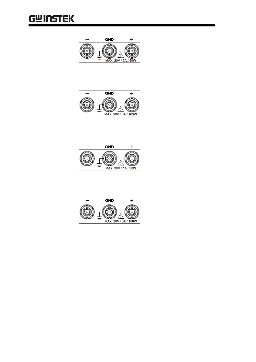
PPX Series Programming Manual
DC output terminal for
PPX is Binding Posts
Terminal or European
Type Jack Terminal.
PPX-2002 the max. output
is 20V/2A/40W
DC output terminal for
PPX is Binding Posts
Terminal or European
Type Jack Terminal.
PPX-2005 the max. output
is 20V/5A/100W
DC output terminal for
PPX is Binding Posts
Terminal or European
Type Jack Terminal.
PPX-3601 the max. output
is 36V/1A/36W
DC output terminal for
PPX is Binding Posts
Terminal or European
Type Jack Terminal.
PPX-3603 the max. output
is 36V/3A/108W
16
Display Area
The display area shows set values, output values
and parameter settings.
14

Display Area
1
2
3
4
5 6
7
8
9
10
17
16
15
14 12
13
11
1
2
3
4
5 6
7
10
17
16
15
14 12
13
11
1.
2Wire/4Wire
2-wire or 4-wire indicator.
2.
Voltage Meter
Displays the voltage.
3.
Current Meter
Displays the current.
4.
V/A Set
Guidance
The scrolling symbol indicates to select
between V and A set via scrolling knob key.
External CC &
CV Control
When the external CC or CV control is
activated, the indicator(s) will be shown.
5.
V Set
Manually sets voltage.
6.
I(A) Set
Manually sets current.
7.
Dlog Icon
When Data Logger is enabled, the icon will be
shown accordingly. Note that when SEQ
appears, the icon will be faded out.
SEQ
When Sequence function is turned On, the icon
will be shown accordingly.
GETTING STARTED
15

PPX Series Programming Manual
8.
DLY Icon
When Output On/Off Dly is enabled, the icon
will be shown accordingly. Note that when
SEQ appears, the icon will be faded out.
9.
VSR/ISR
Icon
When CV/CC Slew Rate Priority (CVLS/CCLS)
is activated, the icon will be shown. Note that
when SEQ appears, the icon will be faded out.
10.
CC/CV/UR
indicator
It shows when constant voltage or constant
current mode is ongoing. However, when output
is unregulated, which means neither in CV mode
nor CC mode, it shows UR instead. If it is not
under power output, it simply shows Off.
11.
LAN Indicator
When PPX series connects to LAN network, the
icon will be shown.
12.
Remote Control
Indicator
When remote control (USB/LAN/GPIB,
UART) is underway, the icon will be shown.
13.
USB Indicator
When USB disk is inserted into the front panel
of PPX series, the icon will be shown.
14.
External Output
Indicator
When external output enable is turned On, the
icon will be shown.
15.
Lock Indicator
When the lock mode is activated, the icon will
be shown.
16.
Communication
Monitor
Indicator
When communication monitor is enabled, the
icon will be shown.
17.
Error Indicator
When error occurs from command of remote
control, the icon will be shown.
16

Rear Panel
5
2
1
3
4
6
7
8
1.
Remote-OUT
RJ-45 connector that is used to daisy chain power
supplies with the Remote-IN port to form a
communication bus.
2.
Remote-IN
Two different types of cables can be used for
RS232 or RS485-based remote control.
PSU-232: RS232 cable with DB9 connector kit.
PSU-485: RS485 cable with DB9 connector kit.
3.
LAN
Ethernet port for controlling the PPX remotely
4.
USB
USB port for controlling the PPX remotely.
GETTING STARTED
17

PPX Series Programming Manual
5.
GPIB
GPIB connector for units equipped with IEEE
programming option. (Factory Installed Options)
6.
EXT I/O
External analog remote control connector.
7.
Line Voltage
Input
AC inlet.
8.
AC Select
Switch
The AC selector is located at the
bottom side of the unit.
Switch Voltage to 100V, 120V,
220V or 240V.
18

GETTING STARTED
Background
The PPX power supplies are regulated DC
power supplies with a stable voltage and
current output. These operate within a switch
automatically between constant voltage and
constant current according to changes in the
load.
Suitable supply cord set for use with the equipment:
Mains plug: shall be national approval
Mains connector: C13 type
Cable:
1. Length of power supply cord: less
than 3m
2. Cross-section of conductors: at least
0.75mm2
3. Cord type: shall meet the
requirements of IEC 60227 or IEC
60245 (e.g.: H05VV-F, H05RN-F)
Caution
If the equipment is used in a manner not specified
by the manufacturer, the protection provided by
the equipment may be impaired.
Theory of Operation
The theory of operation chapter describes the basic principles of
operation, protection modes and important considerations that
must be taken into account before use.
Operating Description
19

PPX Series Programming Manual
CC and CV mode
Description
When the power supply is operating in
constant current mode (CC) a constant current
will be supplied to the load. When in constant
current mode the voltage output can vary,
whilst the current remains constant. When the
load resistance increases to the point where the
set current limit (I
SET
) can no longer be
sustained the power supply switches to CV
mode. The point where the power supply
switches modes is the crossover point.
When the power supply is operating in CV
mode, a constant voltage will be supplied to
the load, whilst the current will vary as the
load varies. At the point that the load
resistance is too low to maintain a constant
voltage, the power supply will switch to CC
mode and maintain the set current limit.
The conditions that determine whether the
power supply operates in CC or CV (V
SET
), the
load resistance (RL) and the critical resistance
(RC). The critical resistance is determined by
V
SET/ISET
. The power supply will operate in CV
mode when the load resistance is greater than
the critical resistance. This means that the
voltage output will be equal to the V
SET
voltage
but the current will be less than I
SET
. If the load
resistance is reduced to the point that the
current output reaches the I
SET
level, the power
supply switches to CC mode.
CC and CV Mode
20

GETTING STARTED
Conversely the power supply will operate in
CC mode when the load resistance is less than
the critical resistance. In CC mode the current
output is equal to I
SET
and the voltage output is
less than V
SET
.
RL=R
C
RL<R
C
VSET
ISET
CV
CC
V
I
RL>R
C
Crossover
point
Theory
The PPX has selectable slew rates for CC and
CV mode. This gives the PPX power supply the
ability to limit the current/voltage draw of the
power supply. Slew rate settings are divided
into High Speed Priority and Slew Rate
Priority. High speed priority mode will use the
fastest slew rate for the instrument. Slew Rate
Priority mode allows for user adjustable slew
rates for CC or CV mode. The rising and falling
slew rate can be set independently.
Slew Rate
21

PPX Series Programming Manual
High Speed
Priority
mode
Slew rate =
Enabled
Background
The PPX DC power supplies employ a bleed
resistor in parallel with the output terminals.
PPX
Load
Bleed
resistor
Bleed resistors are designed to dissipate the
power from the power supply filter capacitors
when power is turned off and the load is
disconnected. Without a bleed resistor, power
may remain charged on the filter capacitors for
some time and be potentially hazardous.
In addition, bleed resistors also allow for
smoother voltage regulation of the power
supply as the bleed resistor acts as a minimum
voltage load.
The bleed resistance can be turned on or off
using the configuration settings.
Bleeder Control
22

GETTING STARTED
Note
By default the bleed resistance is on. For battery
charging applications, be sure to turn the bleed
resistance off as the bleed resistor can discharge
the connected battery when the unit is off.
OVP
Over voltage protection (OVP) prevents a high
voltage from damaging the load. This alarm
can be set by the user.
OCP
Over current protection prevents high current
from damaging the load. This alarm can be set
by the user.
UVL
Under voltage limit. This function sets a
minimum voltage setting level for the output.
It can be set by the user.
OTP
Over temperature protection protect the
instrument from overheating
AC ALARM
When AC input voltage or frequency is
abnormal or beyond the AC power range
under operation, the alarm will be generated.
SENSE ALARM
This alarm function is activated when real
output voltage is larger than sense output
voltage.
Alarm output
Alarms are output via the analog control
connector. The alarm output is an isolated
open-collector photo coupler output.
Alarms
The PPX power supplies have a number of protection features.
When one of the protection alarms is set, the ALM icon on the
display will be lit.
23

PPX Series Programming Manual
Inrush current
When the power supply switch is first turned
on, an inrush current is generated. Ensure there
is enough power available for the power
supply when first turned on, especially if a
number of units are turned on at the same
time.
Caution
Cycling the power on and off quickly can cause the
inrush current limiting circuit to fail as well as
reduce the working life of the input fuse and power
switch.
Pulsed or Peaked
loads
When the load has current peaks or is pulsed, it
is possible for the maximum current to exceed
the mean current value. The PPX power supply
ammeter only indicates mean current values,
which means for pulsed current loads, the
actual current can exceed the indicated value.
For pulsed loads, the current limit must be
increased, or a power supply with a greater
capacity must be chosen. As shown below, a
pulsed load may exceed the current limit and
the indicated current on the power supply
ammeter.
Considerations
The following situations should be taken into consideration when
using the power supply.
24

GETTING STARTED
Current limit
level
Measured
Ammeter
current
Reverse Current:
Regenerative load
When the power supply is connected to a
regenerative load such as a transformer or
inverter, reverse current will feed back to the
power supply. The PPX power supply cannot
absorb reverse current. For loads that create
reverse current, connect a resistor in parallel
(dummy load) to the power supply to bypass
the reverse current. To calculate the resistance
for the dummy resistor, RD, first determine the
maximum reverse current, IR, and determine
what the output voltage, EO, will be.
RD(Ω) ≤ EO(V) ÷ IR(A)
PPX
Load
R
D
I
R
I
R
-
+
E
O
Output
Current
Note
The current output will decrease by the amount of
current absorbed by the resistor.
Ensure the resistor used can withstand the power
capacity of the power supply/load.
25

PPX Series Programming Manual
Reverse Current:
Accumulative
energy.
When the power supply is connected to a load
such as a battery, reverse current may flow
back to the power supply. To prevent damage
to the power supply, use a reverse-currentprotection diode in series between the power
supply and load.
PPX
Load
Diode
CAUTION
Ensure the reverse withstand voltage of the diode
is able to withstand 2 times the rated output
voltage of the power supply and the forward
current capacity can withstand 3 to 10 times the
rated output current of the power supply.
Ensure the diode is able to withstand the heat
generated in the following scenarios.
When the diode is used to limit reverse voltage,
remote sensing cannot be used.
26

GETTING STARTED
Floating
As the output terminals are floating, the load
and all load cables must have an insulation
capacity that is greater than the isolation
voltage of the power supply.
PPX
Load
Ext-V
Ext-R
Analog
connector
( ) Insulation capacity > isolation voltage
of power supply
WARNING
If the insulation capacity of the load and load
cables are not greater than the isolation voltage of
the power supply, electric shock may occur.
Grounding
The output terminals of the PPX power supplies are isolated with
respect to the protective grounding terminal. The insulation
capacity of the load, the load cables and other connected devices
must be taken into consideration when connected to the protective
ground or when floating.
27

PPX Series Programming Manual
Grounded output
terminal
If the positive or negative terminal is connected
to the protective ground terminal, the
insulation capacity needed for the load and
load cables is greatly reduced. The insulation
capacity only needs to be greater than the
maximum output voltage of the power supply
with respect to ground.
PPX
Load
Ext-V
Ext-R
Analog
connector
( ) Insulation capacity > voltage of power
supply with respect to ground
CAUTION
If using external voltage control, do not ground
the external voltage terminal as this will create a
short circuit.
28

REMOTE CONTROL
Interface Configuration ........................................... 31
USB Remote Interface ............................................................................... 31
Configuration ........................................................................................ 31
USB CDC Function Check ................................................................ 32
GPIB Remote Interface ............................................................................ 39
Configuration ........................................................................................ 39
GPIB Function Check ........................................................................ 40
UART Remote Interface ........................................................................... 44
Configure UART .................................................................................. 44
UART Function Check ....................................................................... 46
Multiple Unit Connection ......................................................................... 47
Multi Unit Connection ........................................................................ 47
Multiple units Function Check .......................................................... 48
Error Message ............................................................................................. 50
Command Errors ................................................................................. 50
Execution Errors .................................................................................. 51
Devic Specific Errors .......................................................................... 53
Query Errors ......................................................................................... 53
Other SCPI Defined Error Values.................................................... 54
Configure Ethernet Connection .............................................................. 55
Web Server Configuration .................................................................. 55
Web Server Remote Control Function Check ................................ 56
Sockets Server Configuration ............................................................. 58
Socket Server Function Check ........................................................... 59
Socket Server Examples .......................................... 64
Visual Basic Example ................................................................................. 64
C++ Example ............................................................................................. 65
LabVIEW Example ................................................................................... 67
Command Syntax .................................................... 68
Command List ........................................................ 72
REMOTE CONTROL
This chapter describes basic configuration of
IEEE488.2 based remote control.
29

PPX Series Programming Manual
Status Register Overview ........................................ 130
Introduction to the Status Registers ........................................................130
The Status Registers ...................................................................................131
Questionable Status Register Group .......................................................132
Operation Status Register Group ............................................................135
Standard Event Status Register Group ...................................................138
Status Byte Register & Service Request Enable Register .....................140
Error List ................................................................. 142
Command Errors ........................................................................................142
Execution Errors ........................................................................................146
Device Specific Errors ...............................................................................148
Query Errors ...............................................................................................149
30

REMOTE CONTROL
USB
Configuration
PC side
connector
Type A, host
PPX side
connector
Rear panel Type B, slave
Speed
1.1 (full speed)
USB Class
CDC (communications device
class)
Steps
1. Connect the USB cable to the rear
panel USB B port.
2. Set the USB setting as Auto or Full.
3. The indicator will be shown when a remote
connection has been established.
Remote
Control
indicator
Interface Configuration
USB Remote Interface
Configuration
31

PPX Series Programming Manual
Background
To test the USB CDC functionality, National
Instruments Measurement and Automation
Explorer can be used. This program is available
on the NI website, www.ni.com., via a search
for the VISA Run-time Engine page, or
“downloads” at the following URL,
http://www.ni.com/visa/
Requirements
Operating System: Windows XP, 7, 8,10
Functionality
check
1. In case of Window 7 64 bits, once the USB Cable
was connected to PC correctly for a while
(around 1 min). It may show below message at
the lower right area of display.
2. Open the "Run" dialog box by pressing and
holding the Windows key and then press the R
key ("Run").
3. Type devmgmt.msc and click "OK".
USB CDC Function Check
32

REMOTE CONTROL
4. The Device Manager will show up CDC-
WXXXXXX on “Other Devices”.
5. Select the CDC-WXXXXXX and click the right
button of mouse to "Update Driver Software".
33

PPX Series Programming Manual
6. Select "Locate and install driver software
manually."
7. Indicate the driver folder to the system and
then press "Next".
And this folder should consist of below 2 files.
Note
The USB driver of PPX can be downloaded from
download area of PPX on the GW Instek website
http://www.gwinstek.com/englobal/Support/download
34

REMOTE CONTROL
8. Windows 7 will install the driver for a while.
9. If everything works fine, you may get below
message. And the COM53 is the USB CDC
ACM port of PPX.
35

PPX Series Programming Manual
10. Double check the "Device Manager". The port
should like below.
Steps 1~10 are for the USB CDC Driver
installation.
11. Start the NI Measurement and Automation
Explorer (MAX) program. Using Windows,
press:
Start>All Programs>National
Instruments>Measurement & Automation
36

REMOTE CONTROL
12. From the Configuration panel access;
My System>Devices and Interfaces>Network
Devices
13. Click Open VISA Test Panel.
12
13
14. Click the Configuration icon,
15. Click on I/O Settings.
16. Make sure the Enable Termination Character
check box is checked, and the terminal
character is \n (Value: xA).
17. Click Apply Changes.
14
15
17
16
18. Click the Input/Output icon.
19. Enter *IDN? in the Select or Enter Command
dialog box if it is not already.
20. Click the Query button.
37

PPX Series Programming Manual
21. The *IDN? query will return the Manufacturer,
model name, serial number and firmware
version in the dialog box.
GW-INSTEK,PPX-10H01,TW123456,V0.A4
18
21
19
20
38

REMOTE CONTROL
Configure GPIB
1. Ensure the PPX is off before proceeding.
2. Connect the GPIB cable (GW Instek part
number: GTL-258) from a GPIB controller to the
GPIB port on the PPX.
3. Turn the PPX on.
4. Set the GPIB Address setting per
application.
5. The indicator will be shown when a remote
connection has been established.
Remote
Control
indicator
GPIB constraints
Maximum 15 devices altogether, 20m cable
length, 2m between each device
Unique address assigned to each device
At least 2/3 of the devices turned On
No loop or parallel connection
GPIB Remote Interface
Configuration
To use GPIB, the optional GPIB option (GW Instek part number:
Option 1) must be installed. This is a factory installed option and
cannot be installed by the end-user. Only one GPIB address can be
used at a time.
39

PPX Series Programming Manual
Background
To test the GPIB functionality, National
Instruments Measurement and Automation
Explorer can be used. This program is available
on the NI website, www.ni.com., via a search
for the VISA Run-time Engine page, or
“downloads” at the following URL,
http://www.ni.com/visa/
Requirements
Operating System: Windows XP, 7, 8, 10
Functionality
check
1. Start the NI Measurement and Automation
Explorer (MAX) program. Using Windows,
press:
Start>All Programs>National
Instruments>Measurement & Automation
2. From the Configuration panel access;
My System>Devices and Interfaces>GPIB
3. Press Scan for Instruments.
GPIB Function Check
40

REMOTE CONTROL
2
3
4. Select the device (GPIB address of PPX) that
now appears in the System>Devices and
Interfaces > GPIB-USB-HS “GPIBX” node.
5. Click on the VISA Properties tab on the bottom.
6. Click Open Visa Test Panel.
41

PPX Series Programming Manual
4
5
6
7. Click on Configuration.
8. Click on the GPIB Settings tab and confirm that
the GPIB settings are correct.
7
8
9. Click on the I/O Settings tab.
10. Make sure the Enable Termination Character
check box is checked, and the terminal
character is \n (Value: xA).
11. Click Apply Changes.
42

REMOTE CONTROL
10
9
11
12. Click on Input/Output.
13. Click on the Basic I/O tab.
14. Enter *IDN? in the Select or Enter Command drop
down box.
15. Click Query.
16. The *IDN? query will return the Manufacturer,
model name, serial number and firmware
version in the dialog box.
GW-INSTEK,PPX-10H01,TW123456,V0.A4
43

PPX Series Programming Manual
12
13
15
16
14
Note
For further details, please see the programming
manual, available on the GW Instek web site @
www.gwinstek.com.
Overview
The PPX uses the IN & OUT ports for UART
communication coupled with RS232 (GW Instek
part number: GTL-259) or RS485 adapters (GW
Instek part number: GTL-260).
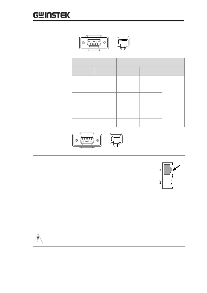
The pin outs for the adapters are shown below.
RS232 cable with
DB9 & RJ-45
shielded
connectors from
GTL-259
connection kit
DB-9 Connector
Remote IN Port
Remarks
Pin No.
Name
Pin No.
Name
Housing
Shield
Housing
Shield
2 RX 7 TX
Twisted
pair
3
TX 8 RX
5
SG 1 SG
UART Remote Interface
Configure UART
44
REMOTE CONTROL
5 1
9 6
1 8
RS485 cable with
DB9 & RJ-45
shielded
connectors from
GTL-260
connection kit
DB-9 Connector
Remote IN Port
Remarks
Pin No.
Name
Pin No.
Name
Housing
Shield
Housing
Shield
9 TXD -
6
RXD -
Twisted
pair
8
TXD +
3
RXD +
1
SG 1 SG 5
RXD -
5
TXD -
Twisted
pair
4
RXD +
4
TXD +
5 1
9 6
1 8
Steps
1. Connect the RS232 serial cable or
RS485 serial cable to the Remote IN
port on the real panel. Connect the
other end of the cable to the PC.
RS232
/ RS485
1
2. Select RS485 or RS232 for Mode
setting. Also set UART relevant
settings including Baud Rate, Data
Bits, Parity, Stop Bits and Address.
Note
When RS232 Mode is selected, the Address setting
is not available for assignation.
45
PPX Series Programming Manual
3. The indicator will be shown when a remote
connection has been established.
Remote
Control
indicator
Functionality
check
Invoke a terminal application such as Realterm.
To check the COM port No., see the Device
Manager in the PC
Run this query command via the terminal
application after the instrument has been
configured for UART remote control.
*idn?
This should return the Manufacturer, Model
number, Serial number, and Firmware version
in the following format.
GW-INSTEK,PPX-10H01,TW123456,V0.A4
Manufacturer: GW-INSTEK
Model number : PPX-10H01
Serial number : TW1234567
Firmware version : V0.A4
Note
For further details, please see the programming
manual, available on the GW Instek web site @
www.gwinstek.com.
UART Function Check
46
REMOTE CONTROL
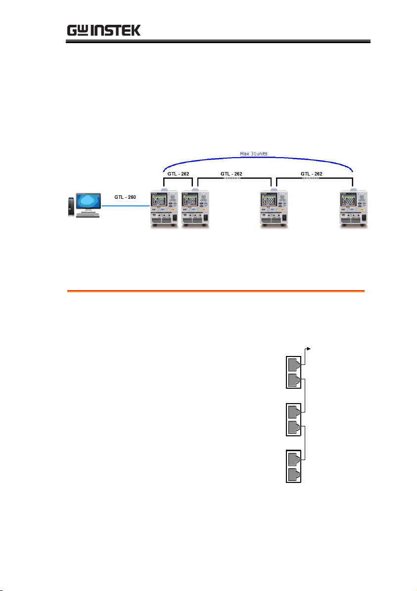
Operation
1. Connect the first unit's IN port to a PC using
RS485 cable with DB9 & RJ-45.
2. Connect the OUT port
on the first unit to the IN
port of the second unit
using the slave serial link
cable (black plug)
supplied in the GTL-262
connection kit.
To PC
IN
IN
serial link cable
(black plug)
Unit #1
OUT
IN
RS 485/232
Unit #2
RS 485/232
Unit #N
RS 485/232
OUT
OUT
PSU-485 cable
with DB9 & RJ-45
serial link cable
(black plug)
3. Power up all units.
Multiple Unit Connection
The PPX power supplies can have up to 31 units daisy-chained
together using the 8 pin connectors (IN OUT ports) on the rear
panel. The first unit in the chain is remotely connected to a PC
using GTL-260 (RS485 cable with DB9 connector).Each subsequent
unit is daisy-chained to the next using a RS485 local bus.
Each unit is assigned a unique address and can then be
individually controlled from the host PC.
Multi Unit Connection
47

PPX Series Programming Manual
4. Set the addresses and mode of all units using
UART menu. It must be a unique address
identifier and mode select is RS485.
5. Multiple units can be operated using SCPI
commands now. See the programming manual
or see the function check below for usage
details.
Functionality
check
Invoke a terminal application such as Realterm.
To check the COM port No, see the Device
Manager in the PC.
For this function check, we will assume that the
one unit is assigned to address 0, while other is
assigned address 5.
ADR 0
OK
*IDN?
GW-INSTEK,PPX-2005,TW123456,V0.A2
VOLT 5
OK
VOLT?
+5.000
Multiple units Function Check
48

REMOTE CONTROL
ADR is followed by address, which can be 0
to 31 and is used to access the power supply.
Selects the unit with address 0 and returns
its identity string. Also, sets its volt as 5 and
returns its volt in 5.
ADR 5
OK
*IDN?
GW-INSTEK,PPX-3601,TW654321,V0.A2
VOLT 10
OK
VOLT?
+10.000
ADR is followed by address, which can be 0
to 31 and is used to access the power supply.
Selects the unit with address 5 and returns
its identity string. Also, sets its volt as 10
and returns its volt in 10.
Note
All setting commands must return an “OK”
response, via a following “Read” action by user,
before any other commands are accepted. The
power supply acknowledges received commands
by returning an “OK” message. If no Read action is
executed after a setting command, and user
proceed to another query command, there will be
something issue occurred within the returned
message where an OK message will be shown
prior to the returned message corresponding to
the query command.
When an error is detected the power supply will
return an error message. For further details, please
see the programming manual, available on the GW
Instek web site @ www.gwinstek.com.
49

PPX Series Programming Manual
Overview
The command error bit in the standard Event
Status Register (ESR) is set to ‘1' when such an
error occurs.
Error Code
Description
E-100
Command error
E-101
Invalid character
E-102
Syntax error
E-103
Invalid separator
E-104
Data type error
E-105
GET not allowed
E-108
Parameter not allowed
E-109
Missing parameter
E-110
Command header error
E-111
Header separator error
E-112
Program mnemonic too long
E-113
Undefined header
E-114
Header suffix out of range
E-115
Unexpected number of parameters
E-120
Numeric data error
E-121
Invalid character in number
E-123
Exponent too large
E-124
Too many digits
E-128
Numeric data not allowed
E-130
Suffix error
E-131
Invalid suffix
E-134
Suffix too long
E-138
Suffix not allowed
E-140
Character data error
E-141
Invalid character data
E-144
Character data too long
Error Message
If an error is detected in command or query, the power supply will
respond with an error message.
Command Errors
50

E-148
Character data not allowed
E-150
String data error
E-151
Invalid string data
E-158
String data not allowed
E-160
Block data error
E-161
Invalid block data
E-168
Block data not allowed
E-170
Expression error
E-171
Invalid expression
E-178
Expression data not allowed
E-180
Macro error
E-181
Invalid outside macro definition
E-183
Invalid inside macro definition
E-184
Macro parameter error
Execution Errors
Overview
The execution error bit in the standard Event
Status Register (ESR) is set to ‘1' when such an
error occurs.
Error Code
Description
E-200
Execution error
E-201
Invalid while in local
E-202
Settings lost due to rtl
E-203
Command protected
E-210
Trigger error
E-211
Trigger ignored
E-212
Arm ignored
E-213
Init ignored
E-214
Trigger deadlock
E-215
Arm deadlock
E-220
Parameter error
E-221
Settings conflict
E-222
Data out of range
E-223
Too much data
E-224
Illegal parameter value
E-225
Out of memory
E-226
Lists not same length
REMOTE CONTROL
51

PPX Series Programming Manual
E-230
Data corrupt or stale
E-231
Data questionable
E-232
Invalid format
E-233
Invalid version
E-240
Hardware error
E-241
Hardware missing
E-250
Mass storage error
E-251
Missing mass storage
E-252
Missing media
E-253
Corrupt media
E-254
Media full
E-255
Directory full
E-256
File name not found
E-257
File name error
E-258
Media protected
E-260
Expression error
E-261
Math error in expression
E-270
Macro error
E-271
Macro syntax error
E-272
Macro execution error
E-273
Illegal macro label
E-274
Macro parameter error
E-275
Macro definition too long
E-276
Macro recursion error
E-277
Macro redefinition not allowed
E-278
Macro header not found
E-280
Program error
E-281
Cannot create program
E-282
Illegal program name
E-283
Illegal variable name
E-284
Program currently running
E-285
Program syntax error
E-286
Program runtime error
E-290
Memory use error
E-291
Out of memory
E-292
Referenced name does not exist
E-293
Referenced name already exists
E-294
Incompatible type
52

REMOTE CONTROL
Overview
The device dependant error bit in the standard
Event Status Register (ESR) is set to '1' when such
an error occurs.
Error Code
Description
E-300
Device-specific error.
E-310
System error.
E-311
Memory error.
E-312
PUD memory lost.
E-313
Calibration memory lost.
E-314
Save/recall memory lost.
E-315
Configuration memory lost.
E-320
Storage fault.
E-321
Out of memory.
E-330
Self-test failed.
E-340
Calibration failed.
E-350
Queue overflow.
E-360
Communication error.
E-361
Parity error in program message.
E-362
Framing error in program message.
E-363
Input buffer overrun.
E-365
Time out error.
Overview
The query error bit in the standard Event Status
Register (ESR) is set to ‘1' when such an error
occurs.
Error Code
Description
E-400
Query error.
E-410
Query INTERRUPTED.
E-420
Query UNTERMINATED.
E-430
Query DEADLOCKED.
E-440
Query UNTERMINATED after indefinite response.
Devic Specific Errors
Query Errors
53

PPX Series Programming Manual
Overview
The corresponding bit in the standard Event Status
Register (ESR) is set to ‘1' when such an event
occurs.
Error Code
Description
E-500
Power on.
E-600
User request.
E-700
Request control.
E-800
Operation complete.
Other SCPI Defined Error Values
54

REMOTE CONTROL
Ethernet
configuration
For details on how to configure the Ethernet
settings, please refer to the User Manual.
Parameters
MAC Address
(display only)
Hostname
(display only)
DHCP On/Off
IP Address
Subnet Mask
Gateway IP
DNS Address
Web Server On/Off
Configuration
This configuration example will configure the
PPX as a web server and use DHCP to
automatically assign an IP address to the PPX.
1. Connect an Ethernet cable from the
network to the rear panel Ethernet
port.
Configure Ethernet Connection
The Ethernet interface can be configured for a number of different
applications. Ethernet can be configured for basic remote control or
monitoring using a web server or it can be configured as a socket
server.
The PPX series supports both DHCP connections so the instrument
can be automatically connected to an existing network or
alternatively, network settings can be manually configured.
Web Server Configuration
55

PPX Series Programming Manual
2. Turn On DHCP and Web Server
settings.
3. The indicator will be shown when a remote
connection has been established.
Remote
Control
indicator
Note
It may be necessary to cycle the power or refresh
the web browser to connect to a network.
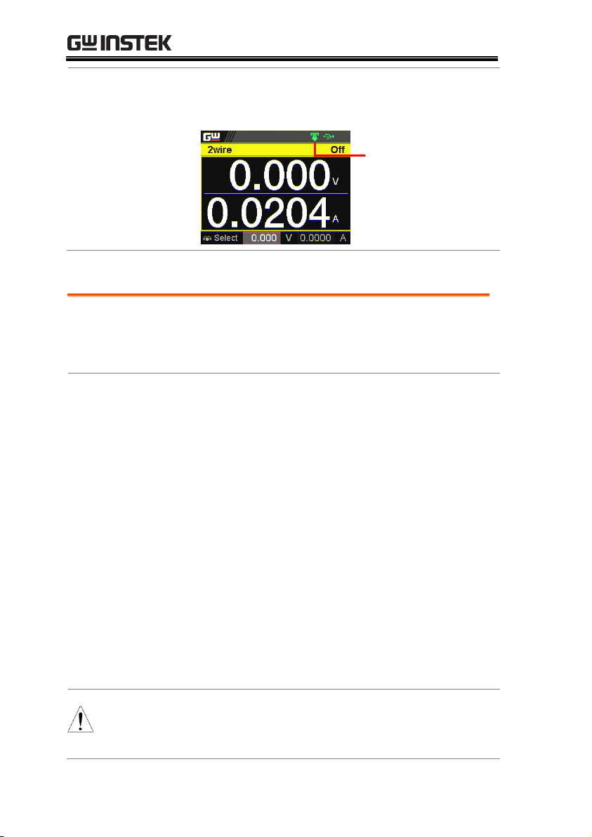
Functionality
check
Enter the IP address of the power supply in a
web browser after the instrument has been
configured as a web server.
The web server allows you to monitor the
function settings of the PPX.
Web Server Remote Control Function Check
56

REMOTE CONTROL
The web browser interface appears as follows.
The web browser interface allows you to access the
following:
Network configuration settings
Measurement setting
Normal Function setting
External Control setting
Temperature Control setting
Analog Control
Figure of Dimension
Sequence setting
Datalog setting
57

PPX Series Programming Manual
Configuration
This configuration example will configure the
PPX socket server.
The following configuration settings will
manually assign the PPX an IP address and
enable the socket server. The socket server port
number is fixed at 2268.
1. Connect an Ethernet cable from the
network to the rear panel Ethernet
port.
2. Turn Off DHCP setting followed by
setting the relevant settings
including IP Address, Subnet Mask,
Gateway IP and DNS Address.
3. The indicator will be shown when a remote
connection has been established.
Remote
Control
indicator
Sockets Server Configuration
58

REMOTE CONTROL
Background
To test the socket server functionality, National
Instruments Measurement and Automation
Explorer can be used. This program is available
on the NI website, www.ni.com., via a search
for the VISA Run-time Engine page, or
“downloads” at the following URL,
http://www.ni.com/visa/
Requirements
Operating System: Windows XP, 7, 8, 10
Functionality
check
1. Start the NI Measurement and Automation
Explorer (MAX) program. Using Windows,
press:
Start>All Programs>National
Instruments>Measurement & Automation
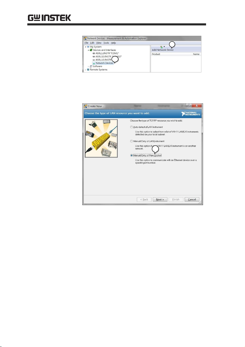
2. From the Configuration panel access;
My System>Devices and Interfaces>Network
Devices
3. Press Add New Network Device>Visa TCP/IP
Resource…
Socket Server Function Check
59
PPX Series Programming Manual
2
3
4. Select Manual Entry of Raw Socket from the
popup window.
4
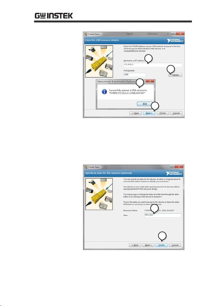
5. Enter the IP address and the port number of the
PPX. The port number is fixed at 2268.
6. Click the Validate button.
7. A popup will appear if a connection is
successfully established.
8. Click Next.
60
REMOTE CONTROL
6
5
7
8
9. Next configure the Alias (name) of the PPX
connection. In this example the Alias is:
PPX_DC1
10. Click finish.
9
10
11. The IP address of the PPX will now appear
under Network Devices in the configuration
panel. Select this icon now.
61

PPX Series Programming Manual
12. Click Open VISA Test Panel.
11
12
13. Click the Configuration icon,
14. Click on I/O Settings.
15. Make sure the Enable Termination Character
check box is checked, and the terminal
character is \n (Value: xA).
16. Click Apply Changes.
14
13
15
16
17. Click the Input/Output icon.
18. Enter *IDN? in the Select or Enter Command
dialog box if it is not already.
19. Click the Query button.
62

REMOTE CONTROL
20. The *IDN? query will return the Manufacturer,
model name, serial number and firmware
version in the dialog box.
GW-INSTEK,PPX-10H01,TW123456,V0.A4
18
17
19
20
Note
For further details, please see the programming
manual, available on the GW Instek web site @
www.gwinstek.com.
63
PPX Series Programming Manual
Visual Basic Example ............................................... 64
C++ Example ........................................................... 65
LabVIEW Example.................................................. 67
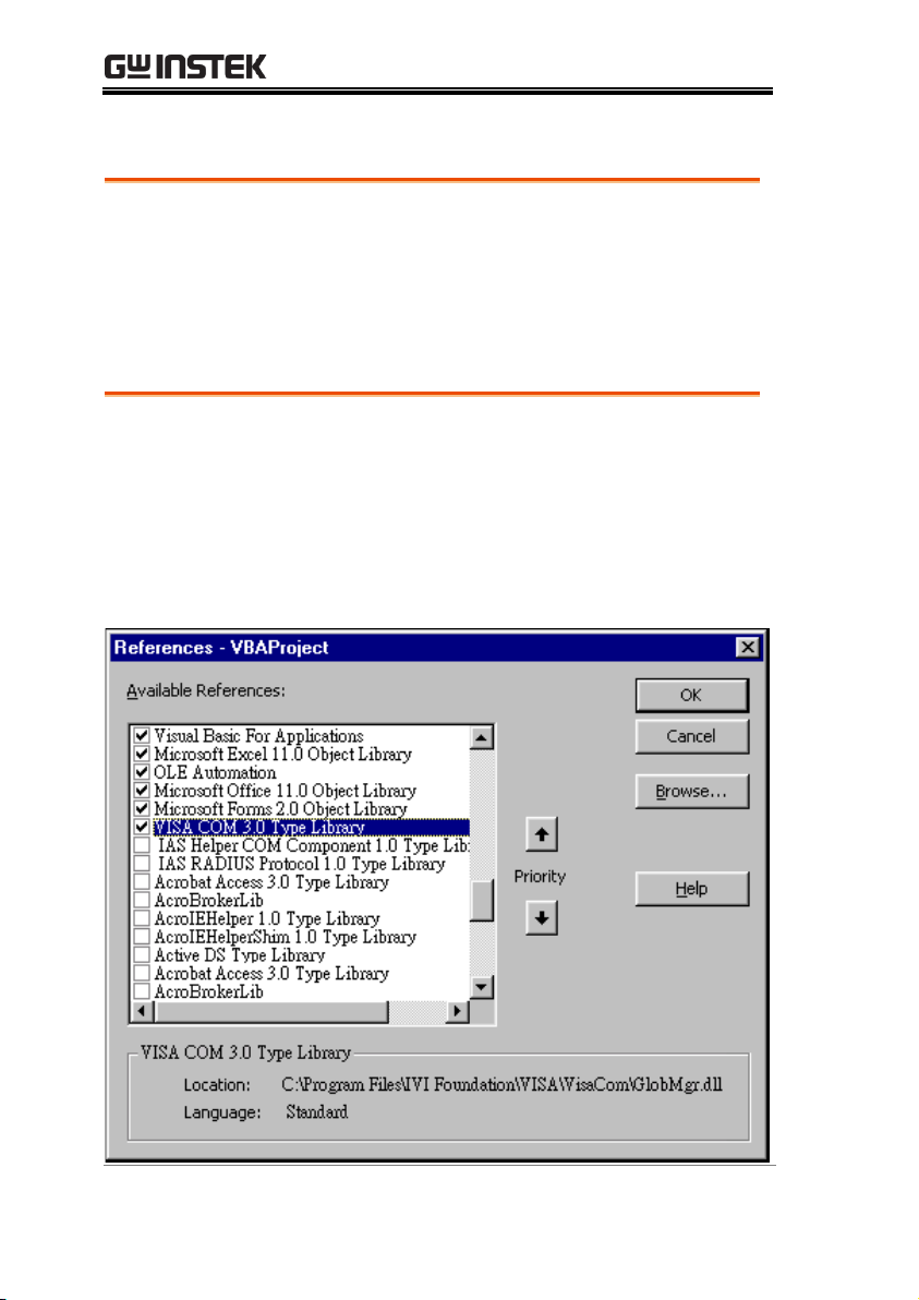
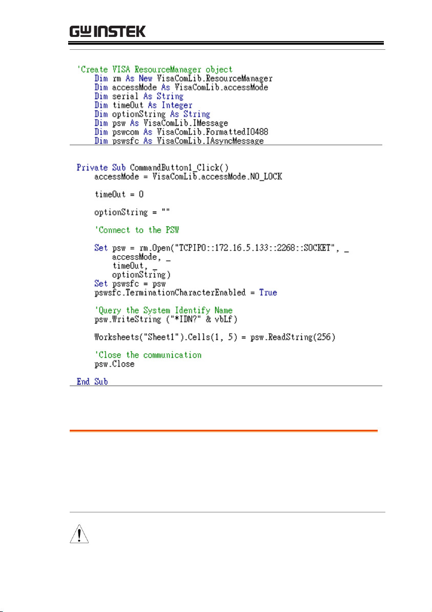
Background
The following visual basic programming
example uses the VISA COM 3.0 Type Library.
The example will connect to the PPX series
using the IP address of 172.15.5.133 over port
2268. The program will send the *IDN? to the
PPX Series, print the return string and then
close the connection.
Socket Server Examples
Visual Basic Example
64
REMOTE CONTROL
Background
The following program creates a connection to
the PPX series and sets the voltage to 3.3 volts
and the current 1.5 amps. The voltage and
current reading is then read back and the
connection is closed.
Note
Add visa32.lib to the project library when
building the following sample program.
C++ Example
65

PPX Series Programming Manual
66

REMOTE CONTROL
Background
The following picture shows a LabView
programming example for the PPX Series.
LabVIEW Example
67

PPX Series Programming Manual
Compatible
Standard
IEEE488.2
Partial compatibility
SCPI, 1999
Partial compatibility
Command
Structure
SCPI commands follow a tree-like structure,
organized into nodes. Each level of the
command tree is a node. Each keyword in a
SCPI command represents each node in the
command tree. Each keyword (node) of a SCPI
command is separated by a colon (:).
For example, the diagram below shows an SCPI
sub-structure and a command example.
DC
MEASure
SCALar
POWer
VOLTage
CURRent
DC
DC
MEASure:SCALar:CURRent:DC?
Command types
There are a number of different instrument
commands and queries. A command sends
instructions or data to the unit and a query
receives data or status information from the
unit.
Command types
Simple
A single command
with/without a parameter
Example
*IDN?
Command Syntax
68

REMOTE CONTROL
Query
A query is a simple or
compound command
followed by a question mark
(?). A parameter (data) is
returned.
Example
meas:curr:dc?
Compound
Two or more commands on
the same command line.
Compound commands are
separated with either a semicolon (;) or a semi-colon and a
colon (;:).
A semi-colon is used to join
two related commands, with
the caveat that the last
command must begin at the
last node of the first
command.
A semi-colon and colon are
used to combine two
commands from different
nodes.
Example
meas:volt:dc?;:meas:curr:dc?
69

PPX Series Programming Manual
Command Forms
Commands and queries have two different
forms, long and short. The command syntax is
written with the short form of the command in
capitals and the remainder (long form) in lower
case.
The commands can be written in capitals or
lower-case, just so long as the short or long
forms are complete. An incomplete command
will not be recognized.
Below are examples of correctly written
commands.
Long
form
STATus:OPERation:NTRansition?
STATUS:OPERATION:NTRANSITION?
status:operation:ntransition?
Short
form
STAT:OPER:NTR?
stat:oper:ntr?
Square Brackets
Commands that contain square brackets
indicate that the contents are optional. The
function of the command is the same with or
without the square bracketed items, as shown
below.
Both “DISPlay:MENU[:NAME]?” and
“DISPlay:MENU?” are both valid forms.
Command
Format
1.5,5.2
1 2 3 4 5
APPLY
1. Command header
2. Space
3. Parameter 1
4. Comma (no space
before/after comma)
5. Parameter 2
Parameters
Type
Description
Example
<Boolean>
Boolean logic
0, 1
70

REMOTE CONTROL
<NR1>
integers
0, 1, 2, 3
<NR2>
decimal
numbers
0.1, 3.14, 8.5
<NR3>
floating point
4.5e-1, 8.25e+1
<NRf>
any of NR1, 2, 3
1, 1.5, 4.5e-1
<block data>
Definitive length arbitrary block
data. A single decimal digit
followed by data. The decimal
digit specifies how many 8-bit
data bytes follow.
Message
Terminator
LF
Line feed code
71

PPX Series Programming Manual
Abort Command
:ABORt ....................................................................... 76
Apply Commands
:APPLy ........................................................................ 76
Address Commands
:ADR ........................................................................... 77
Initiate Commands
:INITiate:CONTinuous[:TRANsient] ................... 77
:INITiate[:IMMediate]:NAME ............................... 78
:INITiate[:IMMediate][:TRANsient] ..................... 78
Memory
Commands
:MEMory:TRIGgered ............................................... 79
Measure
Commands
:MEASure[:SCALar]:ALL[:DC] .............................. 80
:MEASure[:SCALar]:CURRent[:DC] .................... 80
:MEASure[:SCALar]:VOLTage[:DC] .................... 80
:MEASure[:SCALar]:POWer[:DC] ........................ 81
:MEASure[:SCALar]:CURRent:RANGe .............. 81
:MEASure[:SCALar]:VOLTage:RANGe .............. 81
:MEASure:TEMPerature ......................................... 82
Output Commands
:OUTPut:DELay:ON ............................................... 83
:OUTPut:DELay:OFF ............................................. 83
:OUTPut:MODE ...................................................... 84
:OUTPut[:STATe][:IMMediate] ............................. 84
:OUTPut[:STATe]:TRIGgered ............................... 84
:OUTPut:PROTection:CLEar ................................ 85
:OUTPut:PROTection:TRIPped ........................... 85
:OUTPut:PROTection:WDOG[:STATe] ............. 85
:OUTPut:PROTection:WDOG:DELay ............... 85
Command List
72

REMOTE CONTROL
Sense Commands
:SENSe:AVERage:COUNt ..................................... 86
:SENSe:DLOG:SFOL ............................................. 86
:SENSe:DLOG:STATe ........................................... 87
:SENSe:DLOG:PERiod .......................................... 87
:SENSe:AHOur:RESet .............................................. 87
:SENSe:WHOur:RESet ............................................. 87
Status Commands
:STATus:OPERation[:EVENt] .............................. 88
:STATus:OPERation:CONDition ......................... 88
:STATus:OPERation:ENABle ............................... 89
:STATus:OPERation:PTRansition ........................ 89
:STATus:OPERation:NTRansition ....................... 89
:STATus:QUEStionable[:EVENt] ......................... 89
:STATus:QUEStionable:CONDition ................... 90
:STATus:QUEStionable:ENABle .......................... 90
:STATus:QUEStionable:PTRansition ................... 90
:STATus:QUEStionable:NTRansition .................. 91
:STATus:PRESet ....................................................... 91
Source Commands
[:SOURce]:CURRent[:LEVel][:IMMediate]
[:AMPLitude] ............................................................. 92
[:SOURce]:CURRent[:LEVel]:TRIGgered
[:AMPLitude] ............................................................. 93
[:SOURce]:CURRent:LIMit:AUTO ...................... 93
[:SOURce]:CURRent:PROTection:DELay .......... 94
[:SOURce]:CURRent:PROTection[:LEVel] ........ 94
[:SOURce]:CURRent:PROTection:TRIPped ...... 95
[:SOURce]:CURRent:SLEWrate:RISing ............... 95
[:SOURce]:CURRent:SLEWrate:FALLing .......... 96
[:SOURce]:MODE? .................................................. 96
[:SOURce]:VOLTage[:LEVel][:IMMediate]
[:AMPLitude] ............................................................. 97
[:SOURce]:VOLTage[:LEVel]:TRIGgered
[:AMPLitude] ............................................................. 97
[:SOURce]:VOLTage:LIMit:AUTO ...................... 98
[:SOURce]:VOLTage:LIMit:LOW ........................ 98
[:SOURce]:VOLTage:PROTection[:LEVel] ........ 99
[:SOURce]:VOLTage:PROTection:TRIPped ...... 99
[:SOURce]:VOLTage:SLEWrate:RISing .............. 99
[:SOURce]:VOLTage:SLEWrate:FALLing .......... 100
[:SOURce]:VOLTage:SENSe ................................. 100
73

PPX Series Programming Manual
[:SOURce]:POWer[:LEVel][:IMMediate][:AMPLitu
de] ................................................................................ 101
[:SOURce]:POWer:CONTrol ................................. 101
System Commands
:SYSTem:BEEPer[:IMMediate] .............................. 103
:SYSTem:CONFigure:BEEPer[:STATe] .............. 104
:SYSTem:CONFigure:BLEeder[:STATe] ............. 104
:SYSTem:CONFigure:CURRent:CONTrol ......... 105
:SYSTem:CONFigure:VOLTage:CONTrol ........ 105
:SYSTem:CONFigure:OUTPut:PON[:STATe] .. 106
:SYSTem:CONFigure:OUTPut:EXTernal:MODE
...................................................................................... 107
:SYSTem:CONFigure:OUTPut:EXTernal[:STATe]
...................................................................................... 107
:SYSTem:CONFigure:TRIGger:INPut:SOURce 108
:SYSTem:CONFigure:TRIGger:INPut:LEVel .... 108
:SYSTem:CONFigure:TRIGger:OUTPut:SOURce
...................................................................................... 108
:SYSTem:CONFigure:TRIGger:OUTPut:WIDTh
...................................................................................... 109
:SYSTem:CONFigure:TRIGger:OUTPut:LEVel
...................................................................................... 109
:SYSTem:CONFigure:TEMPerature:CONTrol .. 110
:SYSTem:CONFigure:TEMPerature:UNIT ........ 110
:SYSTem:CONFigure:TEMPerature:OUTPut:SAF
E ................................................................................... 111
:SYSTem:CONFigure:TEMPerature:MONitor .. 111
:SYSTem:CONFigure:TEMPerature:ADJust ...... 112
:SYSTem:COMMunicate:ENABle ........................ 112
:SYSTem:COMMunicate:GPIB[:SELF]:ADDRess
...................................................................................... 113
:SYSTem:COMMunicate:LAN:IPADdress .......... 113
:SYSTem:COMMunicate:LAN:GATeway ........... 114
:SYSTem:COMMunicate:LAN:SMASk ................ 114
:SYSTem:COMMunicate:LAN:MAC .................... 114
:SYSTem:COMMunicate:LAN:DHCP ................. 115
:SYSTem:COMMunicate:LAN:DNS .................... 115
:SYSTem:COMMunicate:RLSTate ........................ 115
:SYSTem:COMMunicate:TCPip:CONTrol ......... 116
:SYSTem:COMMunicate:SERial[:RECeive] :TRAN
smit:BAUD ................................................................ 116
:SYSTem:COMMunicate:SERial[:RECeive] :TRAN
smit:BITS .................................................................... 116
74

REMOTE CONTROL
:SYSTem:COMMunicate:SERial[:RECeive] :TRAN
smit:PARity ................................................................ 117
:SYSTem:COMMunicate:SERial[:RECeive] :TRAN
smit:SBITs .................................................................. 117
:SYSTem:COMMunicate:USB:FRONt:STATe .. 118
:SYSTem:COMMunicate:USB:REAR:STATe..... 118
:SYSTem:ERRor ....................................................... 118
:SYSTem:KLOCk ..................................................... 119
:SYSTem:KEYLock:MODE .................................. 119
:SYSTem:ERRor:ENABle ....................................... 119
:SYSTem:PRESet ...................................................... 119
:SYSTem:VERSion ................................................... 119
:SYSTem:KEYBoard:BEEPer .................................. 120
:SYSTem:CAPacity:AHOur ...................................... 120
:SYSTem:CAPacity:WHOur ..................................... 120
:SYSTem:CAPacity:MODE ...................................... 121
:SYSTem:CAPacity:STATe ....................................... 121
Fetch Commands
:FETCh:AHOur? ....................................................... 122
:FETCh:WHOur? ...................................................... 122
Trigger Commands
:TRIGger:OUTPut:SOURce .................................. 123
:TRIGger:OUTPut[:IMMediate] ............................ 123
:TRIGger[:TRANsient]:SOURce ........................... 124
:TRIGger[:TRANsient][:IMMediate]..................... 124
Trigger Command Examples .................................. 125
Common
Commands
*CLS ............................................................................ 126
*ESE ........................................................................... 126
*ESR ............................................................................ 127
*IDN ........................................................................... 127
*OPC ........................................................................... 127
*RCL ........................................................................... 128
*RST ............................................................................ 128
*SAV ........................................................................... 128
*SRE ............................................................................ 128
*STB ............................................................................ 129
*TRG .......................................................................... 129
*TST ............................................................................ 129
*WAI ........................................................................... 129
75

PPX Series Programming Manual
:ABORt ....................................................................... 76
:ABORt
Set
Description
The :ABORt command will cancel any triggered
actions.
Syntax
:ABORt
:APPLy ....................................................................... 76
:APPLy
Set
Query
Description
The apply command sets the voltage and current
at the same time.
Syntax
Query Syntax
:APPLy
{<NRf>(V)|MINimum|MAXimum[,<NRf>(A)|MINimu
m|MAXimum]}
:APPLy?
Parameter/
Return parameter
<NRf>(V)
Voltage setting.
MINimum
Minimum voltage level
MAXimum
Maximum voltage level
<NRf>(A)
Current setting.
MINimum
Minimum voltage level
MAXimum
Maximum voltage level
Example
APPL MIN, MIN
Sets the current and voltage to the minimum settings.
Abort Command
Apply Commands
76

REMOTE CONTROL
:ADR ........................................................................... 77
:ADR
Set
Query
Description
Sets or queries the RS485 interface address.
Syntax
Query Syntax
:ADR <NR1>
:ADR?
Parameter/
Return parameter
<NR1>
0~30
Example
ADR 5
Sets the RS485 address 5.
:INITiate:CONTinuous[:TRANsient] .................. 77
:INITiate[:IMMediate]:NAME .............................. 78
:INITiate[:IMMediate][:TRANsient] ..................... 78
:INITiate:CONTinuous[:TRANsient]
Set
Query
Description
This command continuously initiates software
triggers for the transient or output triggers.
Syntax
Query Syntax
:INITiate:CONTinuous[:TRANsient] {<bool>|OFF|ON}
:INITiate:CONTinuous[:TRANsient]?
Parameter
OFF | 0
OFF
ON | 1
ON
Return parameter
0
OFF
1
ON
Example
INIT:TRAN 1
Turns on the continuous trigger.
Address Commands
Initiate Commands
77

PPX Series Programming Manual
:INITiate[:IMMediate]:NAME
Set
Description
The INITiate command starts the TRANsient or
OUTPut trigger.
Syntax
:INITiate[:IMMediate]:NAME {TRANsient|OUTPut}
Parameter
TRANSient
Starts the TRANsient trigger.
OUTPut
Starts the OUTPut trigger.
Example
INITiate:NAME TRANient
Starts the TRANSient trigger.
:INITiate[:IMMediate][:TRANsient]
Set
Description
This command controls the enabling of output
triggers. When a trigger is enabled, a trigger causes
the specified action to occur. If the trigger system
is not enabled, all triggers are ignored.
Syntax
:INITiate[:IMMediate][:TRANsient]
Example
INIT
78

REMOTE CONTROL
:MEMory:TRIGgered ............................................... 79
:MEMory:TRIGgered
Set
Query
Description
Sets or queries which memory is loaded when a
trigger input is received and the trigger input is
configured to load a memory setting. This is the
equivalent to the TRIG Control menu (Trigin
Memory)settings.
Related
Commands
:SYSTem:CONFigure:TRIGger:INPut:MEMory
{<NR1>|MINimum|MAXimum}
:SYSTem:CONFigure:TRIGger:INPut:MEMory?
[MINimum|MAXimum]
Syntax
Query Syntax
:MEMory:TRIGgered{<NR1>|MINimum|MAXimum}
:MEMory:TRIGgered? [MINimum|MAXimum]
Parameter
<NR1>
MINimum
MAXimum
0(M1)~9(M10).
Return parameter
<NR1>
Returns the memory setting.
Memory Commands
79

PPX Series Programming Manual
:MEASure[:SCALar]:ALL[:DC] ............................. 80
:MEASure[:SCALar]:CURRent[:DC] .................... 80
:MEASure[:SCALar]:VOLTage[:DC] ................... 80
:MEASure[:SCALar]:POWer[:DC] ........................ 81
:MEASure[:SCALar]:CURRent:RANGe .............. 81
:MEASure[:SCALar]:VOLTage:RANGe ............. 81
:MEASure:TEMPerature ......................................... 82
:MEASure[:SCALar]:ALL[:DC]
Query
Description
Takes a measurement and returns the average
output current and voltage
Syntax
:MEASure[:SCALar]:ALL[:DC]?
Return parameter
"+0.0000,+0.00000,+0.000
00"
<voltage>,<current> ,<pow
er>Returns the voltage
(V),current (A),power(W)
respectively.
:MEASure[:SCALar]:CURRent[:DC]
Query
Description
Takes a measurement and returns the average
output current
Syntax
:MEASure[:SCALar]:CURRent[:DC]?
Return parameter
"+0.0000"
Returns the current in amps.
:MEASure[:SCALar]:VOLTage[:DC]
Query
Description
Takes a measurement and returns the average
output voltage.
Syntax
:MEASure[:SCALar]:VOLTage[:DC]?
Return
"+0.0000"
Returns the voltage in volts.
Measure Commands
80
REMOTE CONTROL
:MEASure[:SCALar]:POWer[:DC]
Query
Description
Takes a measurement and returns the average
output power.
Syntax
:MEASure[:SCALar]:POWer[:DC]?
Return
"+0.0000"
Returns the power measured in watts.
:MEASure[:SCALar]:CURRent:RANGe
Set
Query
Description
Sets or queries the current measurement range.
Syntax
Query Syntax
:MEASure[:SCALar]:CURRent:RANGe
{<NR1>|AUTO|IH|IL|ILL}
:MEASure[:SCALar]:CURRent:RANGe?
Parameter
AUTO|0
Current measurement auto range.
IH|1
Current measurement IH range.
IL|2
Current measurement IL range.
ILL|3
Current measurement ILL range.
Return parameter
<NR1>
Returns the current measurement range.
:MEASure[:SCALar]:VOLTage:RANGe
Set
Query
Description
Sets or queries the voltage measurement range.
Syntax
Query Syntax
:MEASure[:SCALar]:VOLTage:RANGe
{<NR1>|AUTO|VH|VL }
:MEASure[:SCALar]:VOLTage:RANGe?
Parameter
AUTO|0
Voltage measurement auto range.
VH|1
Voltage measurement VH range.
VL|2
Voltage measurement VL range.
Return parameter
<NR1>
Returns the voltage measurement range.
81

PPX Series Programming Manual
:MEASure:TEMPerature
Query
Description
Takes a measurement and returns the temperature.
Syntax
:MEASure:TEMPerature?
Return
Return
“+0.0000”
Returns the temperature in celsius or
fahrenheit.
-32768
Returns the temperature in INVAILD.
82

REMOTE CONTROL
:OUTPut:DELay:ON .............................................. 83
:OUTPut:DELay:OFF ............................................ 83
:OUTPut:MODE ..................................................... 84
:OUTPut[:STATe][:IMMediate] ............................ 84
:OUTPut[:STATe]:TRIGgered .............................. 84
:OUTPut:PROTection:CLEar ............................... 85
:OUTPut:PROTection:TRIPped ........................... 85
:OUTPut:PROTection:WDOG[:STATe] ............ 85
:OUTPut:PROTection:WDOG:DELay .............. 85
:OUTPut:DELay:ON
Set
Query
Description
Sets the Delay Time in seconds for turning the
output on. The delay is set to 0.00 by default.
Syntax
Query Syntax
:OUTPut:DELay:ON {<NR2>|MINimum|MAXimum}
:OUTPut:DELay:ON?
Parameter
<NR2>
0.00~359999.99 seconds, where 0=no delay.
Return parameter
"0.00"
Returns the delay on time in seconds until the
output is turned on.
:OUTPut:DELay:OFF
Set
Query
Description
Sets the Delay Time in seconds for turning the
output off. The delay is set to 0.00 by default.
Syntax
Return Syntax
:OUTPut:DELay:OFF {<NR2> |MINimum|MAXimum}
:OUTPut:DELay:OFF?
Parameter
<NR2>
0.00~359999.99 seconds, where 0=no delay.
Return parameter
"0.00"
Returns the delay off time in seconds until the
output is turned off.
Output Commands
83

PPX Series Programming Manual
:OUTPut:MODE
Set
Query
Description
Sets the PPX output mode. This is the equivalent to
the Output menu (V-I Slew Rate Select) settings.
Syntax
Return Syntax
:OUTPut:MODE {<NR1>|CVHS|CCHS|CVLS|CCLS}
:OUTPut:MODE?
Parameter
CVHS | 0
CV high speed priority
CCHS | 1
CC high speed priority
CVLS | 2
CV slew rate priority
CCLS | 3
CC slew rate priority
Return parameter
<NR1>
Returns the output mode.
:OUTPut[:STATe][:IMMediate]
Set
Query
Description
Turns the output on or off.
Syntax
Query Syntax
:OUTPut[:STATe][:IMMediate] { <bool> | OFF | ON }
:OUTPut[:STATe][:IMMediate]?
Parameter
OFF | 0
Turns the output off.
ON | 1
Turns the output on.
Return parameter
<bool>
Returns output status of the instrument.
:OUTPut[:STATe]:TRIGgered
Set
Query
Description
Turns the output on or off when a software trigger
(trigger input) is generated.
Syntax
Query Syntax
:OUTPut[:STATe]:TRIGgered { <bool>|OFF|ON }
:OUTPut[:STATe]:TRIGgered?
Parameter
OFF | 0
Turns the output off when a software trigger
is generated (*TRG).
ON | 1
Turns the output on when a software trigger
is generated (*TRG).
Return parameter
<bool>
Returns output trigger status of the
instrument.
84

REMOTE CONTROL
:OUTPut:PROTection:CLEar
Set
Description
Clears over-voltage, over-current and overtemperature (OVP, OCP, OTP) protection circuits.
It also clears the temperature short and sense
protection circuit .The other alarm(WDOG, CAP,
TEMP Monitor)also clears.
Syntax
:OUTPut:PROTection:CLEar
:OUTPut:PROTection:TRIPped
Query
Description
Queries the unit to see if a protection circuit has
been tripped.
Syntax
:OUTPut:PROTection:TRIPped?
Return
<boolean>
0 = No protection error
1 = A protection error had occured
:OUTPut:PROTection:WDOG[:STATe]
Set
Query
Description
Enables or disables the communication monitor setting.
Syntax
Query Syntax
:OUTPut:PROTection:WDOG[:STATe] { <bool> | OFF | ON }
:OUTPut:PROTection:WDOG[:STATe]?
Parameter
OFF | 0
Disable communication monitor.
ON | 1
Enable communication monitor.
Return parameter
<boolean>
Returns the setting in <bool> format.
:OUTPut:PROTection:WDOG:DELay
Set
Query
Description
Sets the timer in seconds for monitor the
communication.
Syntax
Query Syntax
:OUTPut:PROTection:WDOG:DELay
{<NR1>|MINimum|MAXimum}
:OUTPut:PROTection:WDOG:DELay?
Parameter
<NR1>
1~3600 seconds.
Return parameter
<NR1>
Returns the timer setting.
85

PPX Series Programming Manual
:SENSe:AVERage:COUNt ..................................... 86
:SENSe:DLOG:SFOL ............................................. 86
:SENSe:DLOG:STATe ........................................... 87
:SENSe:DLOG:PERiod .......................................... 87
:SENSe:AHOur:RESet .............................................. 87
:SENSe:WHOur:RESet ............................................. 87
:SENSe:AVERage:COUNt
Set
Query
Description
Sets or queries the level of smoothing for the
average setting.
Syntax
Return Syntax
:SENSe:AVERage:COUNt
{<NR1>|LOW|MIDDle|HIGH}
:SENSe:AVERage:COUNt?
Parameter
OFF | 0
Default setting
LOW | 0
Low setting
MIDDle | 1
Middle setting
HIGH | 2
High setting
Return Parameter
<NR1>
Returns the average setting.
:SENSe:DLOG:SFOL
Set
Query
Description
Sets or queries data logger subfolder counter.
Syntax
Return Syntax
:SENSe:DLOG:SFOL {<string>}
:SENSe:DLOG:SFOL?
Parameter
<string>
ASCII characters: 30H to 39H.
Return Parameter
<string>
Returns ASCII characters: 30H to 39H.
Sense Commands
86

REMOTE CONTROL
:SENSe:DLOG:STATe
Set
Query
Description
Enables or disables the data logger setting.
Syntax
Return Syntax
:SENSe:DLOG:STATe {<NR1>}
:SENSe:DLOG:STATe?
Parameter
0
Disable data logger.
1
Enable data logger.The data is stored in
the USB storage when USB storage plug
in.
2
Enable data logger,The data is sent to the
interface when the remote control read
data.
Return Parameter
<NR1>
Returns the data logger setting.
:SENSe:DLOG:PERiod
Set
Query
Description
Sets the sample period in seconds for data logger.
Syntax
Return Syntax
:SENSe:DLOG:PERiod
{<NR2>|MINimum|MAXimum}
:SENSe:DLOG:PERiod?
Parameter
<NR2>
0.1~999.9 seconds.
Return Parameter
<NR2>
Returns the sample period setting.
:SENSe:AHOur:RESet
Set
Description
Sets the Ampere-hour capacity to zero.
Note: Install the license first.
Syntax
:SENSe:AHOur:RESet
:SENSe:WHOur:RESet
Set
Description
Sets the Watt-hour capacity to zero.
Note: Install the license first.
Syntax
:SENSe:WHOur:RESet
87

PPX Series Programming Manual
:STATus:OPERation[:EVENt] .............................. 88
:STATus:OPERation:CONDition ........................ 88
:STATus:OPERation:ENABle ............................... 89
:STATus:OPERation:PTRansition ........................ 89
:STATus:OPERation:NTRansition ....................... 89
:STATus:QUEStionable[:EVENt] ........................ 89
:STATus:QUEStionable:CONDition ................... 90
:STATus:QUEStionable:ENABle ......................... 90
:STATus:QUEStionable:PTRansition .................. 90
:STATus:QUEStionable:NTRansition ................. 91
:STATus:PRESet ...................................................... 91
:STATus:OPERation[:EVENt]
Query
Description
Queries the Operation Status Event register and
clears the contents of the register.
Syntax
:STATus:OPERation[:EVENt]?
Return
<NR1>
Returns the bit sum of the Operation Status
Event register.
:STATus:OPERation:CONDition
Query
Description
Queries the Operation Status register. This query
will not clear the register.
Syntax
:STATus:OPERation:CONDition?
Return
<NR1>
Returns the bit sum of the Operation
Condition register.
Status Commands
For an overview of all the status registers, their associated register
contents and the system diagram, please see the status overview on
page 130
88

REMOTE CONTROL
:STATus:OPERation:ENABle
Set
Query
Description
Sets or queries the bit sum of the Operation Status
Enable register.
Syntax
Query Syntax
:STATus:OPERation:ENABle <NR1>
:STATus:OPERation:ENABle?
Parameter
<NR1>
0~32767
Return parameter
<NR1>
0~32767
:STATus:OPERation:PTRansition
Set
Query
Description
Sets or queries the bit sum of the positive
transition filter of the Operation Status register.
Syntax
Query Syntax
:STATus:OPERation:PTRansition <NR1>
:STATus:OPERation:PTRansition?
Parameter
<NR1>
0~32767
Return parameter
<NR1>
0~32767
:STATus:OPERation:NTRansition
Set
Query
Description
Sets or queries the bit sum of the negative
transition filter of the Operation Status register.
Syntax
Query Syntax
:STATus:OPERation:NTRansition <NR1>
:STATus:OPERation:NTRansition?
Parameter
<NR1>
0~32767
Return parameter
<NR1>
0~32767
:STATus:QUEStionable[:EVENt]
Query
Description
Queries the bit sum of the Questionable Status
Event register. This query will also clear the
contents of the register.
Query Syntax
:STATus:QUEStionable[:EVENt]?
Return parameter
<NR1>
0~32767
89

PPX Series Programming Manual
:STATus:QUEStionable:CONDition
Query
Description
Queries the status (bit sum) of the Questionable
Status register. This query will not clear the
register.
Query Syntax
:STATus:QUEStionable:CONDition?
Return parameter
<NR1>
0~32767
:STATus:QUEStionable:ENABle
Set
Query
Description
Sets or queries the bit sum of the Questionable
Status Enable register.
Syntax
Query Syntax
:STATus:QUEStionable:ENABle <NR1>
:STATus:QUEStionable:ENABle?
Parameter
<NR1>
0~32767
Return parameter
<NR1>
0~32767
:STATus:QUEStionable:PTRansition
Set
Query
Description
Sets or queries the bit sum of the positive
transition filter of the Questionable Status register.
Syntax
Return Syntax
:STATus:QUEStionable:PTRansition <NR1>
:STATus:QUEStionable:PTRansition?
Parameter
<NR1>
0~32767
Return parameter
<NR1>
0~32767
90

REMOTE CONTROL
:STATus:QUEStionable:NTRansition
Set
Query
Description
Sets or queries the negative transition filter of the
Questionable Status register.
Syntax
Query Syntax
:STATus:QUEStionable:NTRansition <NR1>
:STATus:QUEStionable:NTRansition?
Parameter
<NR1>
0~32767
Return parameter
<NR1>
0~32767
:STATus:PRESet
Set
Description
This command resets the ENABle register, the
PTRansistion filter and NTRansistion filter on the
Operation Status and Questionable Status
Registers. The registers/filters will be reset to a
default value.
Default Register/Filter Values
Setting
QUEStionable Status Enable
0x0000
QUEStionable Status Positive Transition
0x7FFF
QUEStionable Status Negative Transition
0x0000
Operation Status Enable
0x0000
Operation Status Positive Transition
0x7FFF
Operation Status Negative Transition
0x0000
Syntax
:STATus:PRESet
91

PPX Series Programming Manual
[:SOURce]:CURRent[:LEVel][:IMMediate]
[:AMPLitude] ............................................................. 92
[:SOURce]:CURRent[:LEVel]:TRIGgered
[:AMPLitude] ............................................................. 93
[:SOURce]:CURRent:LIMit:AUTO ...................... 93
[:SOURce]:CURRent:PROTection:DELay ......... 94
[:SOURce]:CURRent:PROTection[:LEVel] ........ 94
[:SOURce]:CURRent:PROTection:TRIPped ...... 95
[:SOURce]:CURRent:SLEWrate:RISing .............. 95
[:SOURce]:CURRent:SLEWrate:FALLing .......... 96
[:SOURce]:MODE? ................................................. 96
[:SOURce]:VOLTage[:LEVel][:IMMediate]
[:AMPLitude] ............................................................. 97
[:SOURce]:VOLTage[:LEVel]:TRIGgered
[:AMPLitude] ............................................................. 97
[:SOURce]:VOLTage:LIMit:AUTO ..................... 98
[:SOURce]:VOLTage:LIMit:LOW ........................ 98
[:SOURce]:VOLTage:PROTection[:LEVel] ........ 99
[:SOURce]:VOLTage:PROTection:TRIPped ..... 99
[:SOURce]:VOLTage:SLEWrate:RISing .............. 99
[:SOURce]:VOLTage:SLEWrate:FALLing .......... 100
[:SOURce]:VOLTage:SENSe ................................. 100
[:SOURce]:POWer[:LEVel][:IMMediate][:AMPLitude]
..................................................................................... 101
[:SOURce]:POWer:CONTrol ................................ 101
[:SOURce]:CURRent[:LEVel][:IMMediate]
[:AMPLitude]
Set
Query
Description
Sets or queries the current level in amps. For
externally set current levels (from the analog
control connector) the set current level is returned.
Syntax
[:SOURce]:CURRent[:LEVel][:IMMediate][:AMPLitude]
{<NR2>(A)|MINimum|MAXimum}
Query Syntax
[:SOURce]:CURRent[:LEVel][:IMMediate][:AMPLitude]?
Parameter/Return
<NR2>
0~105% of the rated current output level.
Source Commands
92

REMOTE CONTROL
parameter
MIN
Minimum current level.
MAX
Maximum current level.
Example
SOUR:CURR:LEV:IMM:AMPL?
1.0000
Returns the current level in amps.
[:SOURce]:CURRent[:LEVel]:TRIGgered
[:AMPLitude]
Set
Query
Description
Sets or queries the current level in amps when a
software trigger has been generated.
Syntax
[:SOURce]:CURRent[:LEVel]:TRIGgered[:AMPLitude]
{<NR2> (A)| MINimum|MAXimum}
Query Syntax
[:SOURce]:CURRent[:LEVel]:TRIGgered[:AMPLitude]?
Parameter
<NR2>
0%~105% of the rated current output in amps.
MIN
Minimum current level.
MAX
Maximum current level.
Return Parameter
<NR2>
Returns the current level.
Example
SOUR:CURR:LEV:TRIG:AMPL?
1.0000
Returns the maximum possible current level in amps.
[:SOURce]:CURRent:LIMit:AUTO
Set
Query
Description
Enables or disables the limit on the current setting.
Syntax
[:SOURce]:CURRent:LIMit:AUTO {<bool>|OFF|ON}
Query Syntax
[:SOURce]:CURRent:LIMit:AUTO?
Parameter
OFF | 0
Disable the setting current limit
ON | 1
Enable the setting current limit
Return parameter
<bool>
Returns the setting in <bool> format.
Example
SOUR:CURR:LIM:AUTO 0
Disables the current limit.
93

PPX Series Programming Manual
[:SOURce]:CURRent:PROTection:DELay
Set
Query
Description
Sets the Delay Time for OCP in seconds.
The delay is set to 0.05 by default.
Syntax
[:SOURce]:CURRent:PROTection:DELay
{<NR2>|MINimum|MAXimum}
Query Syntax
[:SOURce]:CURRent:PROTection:DELay?
Parameter
<NR2>
0.05~2.5 seconds
MAX
The maximum allowed delay time
MIN
The minimum allowed delay time
Return parameter
<NR2>
Returns the delay time in seconds
Example
SOUR:CURR:PROT:DEL MAX
Sets the current protection delay to the maximum.
[:SOURce]:CURRent:PROTection[:LEVel]
Set
Query
Description
Sets or queries the OCP (over-current protection)
level in amps.
Syntax
[:SOURce]:CURRent:PROTection[:LEVel] {<NR2>(A)
|MINimum|MAXimum}
Query Syntax
[:SOURce]:CURRent:PROTection[:LEVel]?
Parameter
<NR2>
Current protection level.
Minimum: Irated * 0.05
Maximum: Irated * 1.1
MIN
Minimum current level.
MAX
Maximum current level.
Return parameter
<NR2>
Returns the current protection level.
Example
SOUR:CURR:PROT:LEV?
+5.000
Returns the current level in amps.
94

REMOTE CONTROL
[:SOURce]:CURRent:PROTection:TRIPped
Set
Query
Description
Returns the state of the current protection circuits.
Query Syntax
[:SOURce]:CURRent:PROTection:TRIPped?
Return parameter
<bool>
Returns protection status.
Example
SOUR:CURR:PROT:TRIP?
>0
The protection circuit has not been tripped.
[:SOURce]:CURRent:SLEWrate:RISing
Set
Query
Description
Sets or queries the rising current slew rate. This is only
applicable for CC slew rate priority (CCLS) mode.
Syntax
Query Syntax
[:SOURce]:CURRent:SLEWrate:RISing
{<NR2>(A)|MINimum|MAXimum}
[:SOURce]:CURRent:SLEWrate:RISing?
Parameter
<NR2>
Per step is between 0.00001A/msec and
depend on the unit type: 0.01 /0.02 /0.03
/0.05 A/msec.
MIN
Minimum rising current slew rate is
0.00001A/msec.
MAX
Maximum: Depend on the unit type:
0.01 /0.02 /0.03 /0.05 A/msec.
Return parameter
<NR2>
Returns the step current in amps.
Example
SOUR:CURR:SLEW:RIS?
0.02000
Sets the rising current slew rate to 0.02000 A/ms.
95

PPX Series Programming Manual
[:SOURce]:CURRent:SLEWrate:FALLing
Set
Query
Description
Sets or queries the falling current slew rate. This is only
applicable for CC slew rate priority (CCLS) mode.
Syntax
[:SOURce]:CURRent:SLEWrate:FALLing
{<NR2>(A)|MINimum|MAXimum}
Query Syntax
[:SOURce]:CURRent:SLEWrate:FALLing?
Parameter
<NR2>
Per step is between 0.00001A/msec and
depend on the unit type: 0.01 /0.02 /0.03
/0.05 A/msec.
MIN
Minimum falling current slew rate is
0.00001A/msec.
MAX
Maximum: Depend on the unit type:
0.01 /0.02 /0.03 /0.05 A/msec.
Return Parameter
<NR2>
Returns the step current in amps.
Example
SOUR:CURR:SLEW:FALL MAX
Sets the falling current slew rate to the maximum.
[:SOURce]:MODE?
Set
Query
Description
Returns the status of the output mode (CC, CV,
Off) of the power supply.
The interface will return “CV’ if the supply is in
Constant Voltage Mode, “CC” if the supply is in
Constant Current Mode or “OFF” if the supply
output is off.
Query Syntax
[:SOURce]:MODE?
Return parameter
<string>
Returns the output state as a string, “CC”,
“CV”, “OFF”
Example
:SOUR:MODE?
>CC
The power supply is currently in CC mode.
96

REMOTE CONTROL
[:SOURce]:VOLTage[:LEVel][:IMMediate]
[:AMPLitude]
Set
Query
Description
Sets or queries the voltage level in volts.
Syntax
[:SOURce]:VOLTage[:LEVel][:IMMediate][:AMPLitude]
{<NR2>(V)|MINimum|MAXimum}
Query Syntax
[:SOURce]:VOLTage[:LEVel][:IMMediate][:AMPLitude]?
Parameter
<NRf>
0~105% of the rated output voltage in volts.
MIN
Minimum voltage level
MAX
Maximum voltage level
Return parameter
<NR2>
Returns the voltage level in volts
Example
SOUR:VOLT:LEV:IMM:AMPL 10
Sets the voltage level to 10 volts.
[:SOURce]:VOLTage[:LEVel]:TRIGgered
[:AMPLitude]
Set
Query
Description
Sets or queries the voltage level in volts when a
trigger in/software trigger has been generated.
Syntax
[:SOURce]:VOLTage[:LEVel]:TRIGgered[:AMPLitude]
{<NR2>(V)|MINimum|MAXimum}
Query Syntax
[:SOURce]:VOLTage[:LEVel]:TRIGgered[:AMPLitude]?
Parameter
<NR2>
0%~105% of the rated voltage output in volts.
MIN
Minimum current level.
MAX
Maximum current level.
Return parameter
<NR2>
Returns the voltage level.
Example
SOUR:VOLT:LEV:TRIG:AMPL 10
Sets the voltage level to 10 volts when a software
trigger is generated.
97

PPX Series Programming Manual
[:SOURce]:VOLTage:LIMit:AUTO
Set
Query
Description
Sets whether to limit the voltage setting so that it
does not exceed the OVP setting or become lower
than the UVL setting.
If you enable the limit when the OVP setting is
lower than the voltage setting, the OVP setting will
be set to 105 % of the voltage setting.
If you enable the limit when the UVL setting is
higher than the voltage setting, the UVL setting
will be set equal to the voltage setting.
Syntax
[:SOURce]:VOLTage:LIMit:AUTO {<bool>|OFF|ON}
Query Syntax
[:SOURce]:VOLTage:LIMit:AUTO?
Parameter
OFF | 0
Disable the limit setting
ON | 1
Enable the limit setting
Return parameter
<bool>
Returns the setting in <bool> format.
Example
SOUR:VOLT:LIM:AUTO 0
Disables the limit setting.
[:SOURce]:VOLTage:LIMit:LOW
Set
Query
Description
Sets or queries the under voltage (UVL) trip point.
Syntax
[:SOURce]:VOLTage:LIMit:LOW
<NR2>(V)|MINimum|MAXimum
Query Syntax
[:SOURce]:VOLTage:LIMit:LOW?
Parameter/Return
<NR2>
0 ~ the present setting voltage
MIN
Minimum allowed voltage level
MAX
Maximum allowed voltage level
Example
SOUR:VOLT:LIM:LOW MAX
Sets the UV> level to its maximum.
It can’t setting when voltage limit turn off.
98

REMOTE CONTROL
[:SOURce]:VOLTage:PROTection[:LEVel]
Set
Query
Description
Sets or queries the overvoltage protection level.
Syntax
[:SOURce]:VOLTage:PROTection[:LEVel]
{<NR2>(V)|MINimum|MAXimum}
Query Syntax
[:SOURce]:VOLTage:PROTection[:LEVel]?
Parameter/Return
<NR2>
Minimum: Vrated * 0.05
Maximum: Vrated * 1.1
MIN
Minimum OVP level
MAX
Maximum OVP level
Example
SOUR:VOLT:PROT:LEV MAX
Sets the OVP level to its maximum.
[:SOURce]:VOLTage:PROTection:TRIPped
Set
Query
Description
Sets or queries the overvoltage protection level.
Query Syntax
[:SOURce]:VOLTage:PROTection:TRIPped?
Return parameter
<bool>
0
Protection not tripped
1
Protection tripped
Example
SOUR:VOLT:PROT:TRIP?
>0
Indicates that the OVP protection has not been
tripped.
[:SOURce]:VOLTage:SLEWrate:RISing
Set
Query
Description
Sets or queries the rising voltage slew rate. This is only
applicable for CV slew rate priority (CVLS) mode.
Syntax
Query Syntax
[:SOURce]:VOLTage:SLEWrate:RISing
{<NR2>(V)|MINimum|MAXimum}
[:SOURce]:VOLTage:SLEWrate:RISing?
99

PPX Series Programming Manual
Parameter
<NR2>
Per step is between 0.0001V/msec and
depend on the unit type: 0.1 /0.2 /0.36 /1
V/msec.
MIN
Minimum rising voltage slew rate is
0.0001V/msec.
MAX
Maximum: Depend on the unit type:
0.1 /0.2 /0.36 /1 V/msec.
Return parameter
<NR2>
Returns the slew rate in V/msec.
Example
SOUR:VOLT:SLEW:RIS MAX
Sets the rising voltage slew rate to its maximum.
[:SOURce]:VOLTage:SLEWrate:FALLing
Set
Query
Description
Sets or queries the falling voltage slew rate. This is only
applicable for CV slew rate priority (CVLS) mode.
Syntax
[:SOURce]:VOLTage:SLEWrate:FALLing
{<NR2>(V)|MINimum|MAXimum}
Query Syntax
[:SOURce]:VOLTage:SLEWrate:FALLing?
Parameter
<NR2>
Per step is between 0.0001V/msec and
depend on the unit type: 0.1 /0.2 /0.36 /1
V/msec.
MIN
Minimum falling voltage slew rate is
0.0001V/msec.
MAX
Maximum: Depend on the unit type:
0.1 /0.2 /0.36 /1 V/msec.
Return parameter
<NR2>
Returns the voltage slew rate in V/msec
Example
SOUR:VOLT:SLEW:FALL MIN
Sets the falling voltage slew rate to its minimum.
[:SOURce]:VOLTage:SENSe
Set
Query
Description
Sets or queries the remote sense.
Syntax
[:SOURce]:VOLTage:SENSe
{<NR1>|INTernal|EXTernal}
Query Syntax
[:SOURce]:VOLTage:SENSe?
Parameter
<NR2>
100
 Loading...