

Instek PEL-5006C-150-600, PEL-5008C-1200-320, PEL-5024C-600-1680, PEL-5008-150-800, PEL-5010C-150-1000 User Manual
...
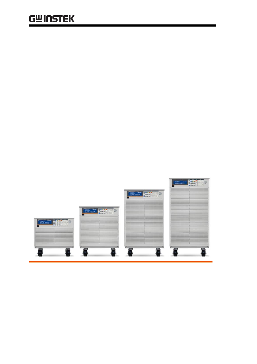
High Power Electronic Load
PEL-5000C Series
USER MANUAL
ISO-9001 CERTIFIED MANUFACTURER

This manual contains proprietary information, which is protected by
copyright. All rights are reserved. No part of this manual may be
photocopied, reproduced or translated to another language without
prior written consent of Good Will company.
The information in this manual was correct at the time of printing.
However, Good Will continues to improve products and reserves the
rights to change specification, equipment, and maintenance
procedures at any time without notice.
Good Will Instrument Co., Ltd.
No. 7-1, Jhongsing Rd., Tucheng Dist., New Taipei City 236, Taiwan.

Table of Contents
Table of Contents
SAFETY INSTRUCTIONS .................................................. 4
GETTING STARTED .......................................................... 8
PEL-5000C Series Introduction .............................. 10
Accessories............................................................ 13
Operating Mode Description ................................. 14
Operating Area ...................................................... 20
Appearance ............................................................ 27
FUNCTION DESCRIPTION ............................................. 38
Function keys description ...................................... 39
Test keys description ............................................. 53
System keys description ........................................ 68
Test keys description ............................................. 77
CONNECTION ............................................................... 79
Rear Panel ............................................................. 80
Connecting the I-monitor to an oscilloscope ......... 84
Master/Slave Instructions ..................................... 85
INSTALLATION .............................................................. 88
Check line voltage .................................................. 89
Grounding requirements ....................................... 89
Power up ............................................................... 90
Connection to the load Input Terminal .................. 90
GPIB & RS232 interface option .............................. 91
RS232 interface option .......................................... 92
GPIB interface option ............................................ 92
USB interface option ............................................. 92
LAN interface option ............................................. 93
I/O connection ...................................................... 93
1

PEL-5000C User Manual
Load current slew rate setting ............................... 94
Load wire inductance ............................................ 96
REMOTE CONTROL ...................................................... 100
Interface Configuration ........................................ 101
Communication Interface programming command
list ....................................................................... 103
Command Syntax ................................................. 115
Command List ..................................................... 117
PRESET Commands ............................................. 119
Limit Commands ................................................. 132
STAGE commands ............................................... 135
System Commands .............................................. 141
Measure Commands ............................................ 143
APPLICATION ............................................................... 144
Local sense connections ...................................... 145
Remote sense connections .................................. 146
Constant Current mode application ..................... 148
Constant Voltage mode application ..................... 151
Constant Resistance mode application ................ 153
Constant Power mode application ....................... 155
CC + CV mode of operation application ............... 157
CP + CV mode of operation application ............... 159
Constant current source operating ....................... 161
Zero-Volt loading application ............................... 162
Parallel operation ................................................ 163
Power Supply OCP testing ................................... 164
Power Supply OPP testing ................................... 166
SHORT testing ..................................................... 168
Battery discharge test .......................................... 171
APPENDIX .................................................................... 175
PEL-5000C Default Settings ................................. 176
PEL-5000C Dimensions ........................................ 183
2

Table of Contents
PEL-5000C series Specifications .......................... 187
Certificate Of Compliance .................................... 208
GPIB programming Example ................................ 209
PEL-5000C series USB Instruction ....................... 213
PEL-5000C series Auto, Sequence function provide
EDIT, ENTER, EXIT, TEST and STORE 5 keys
operation ............................................................. 215
PEL-5000C series LAN Instruction ....................... 219
3
PEL-5000C User Manual
WARNING
Warning: Identifies conditions or practices that
could result in injury or loss of life.
CAUTION
Caution: Identifies conditions or practices that
could result in damage to the instrument or to
other properties.
DANGER High Voltage
Attention Refer to the Manual
Earth (ground) Terminal
Frame or Chassis Terminal
Do not dispose electronic equipment as unsorted
municipal waste. Please use a separate collection
facility or contact the supplier from which this
instrument was purchased.
SAFETY INSTRUCTIONS
This chapter contains important safety instructions that you must
follow during operation and storage. Read the following before any
operation to insure your safety and to keep the instrument in the
best possible condition.
Safety Symbols
These safety symbols may appear in this manual or on the
instrument.
4

SAFETY INSTRUCTIONS
General
Guideline
CAUTION
Do not place any heavy object on the
instrument. Note: Only 2 units can be stacked
vertically.
Avoid severe impact or rough handling that
leads to damaging the instrument.
Do not discharge static electricity to the
instrument.
Use only crimped wires, not bare wires, for the
terminals.
Do not block the cooling fan opening.
Do not disassemble the instrument unless you
are qualified.
The equipment is not for measurements
performed for CAT II, III and IV.
(Measurement categories) EN 61010-1:2010 specifies the
measurement categories and their requirements as follows.
Measurement category IV is for measurement performed at the
source of low-voltage installation.
Measurement category III is for measurement performed in the
building installation.
Measurement category II is for measurement performed on the
circuits directly connected to the low voltage installation.
0 is for measurements performed on circuits not directly
connected to Mains.
Do NOT position the equipment so that it is
difficult to disconnect the appliance inlet or the
power plug.
If the equipment is used in a manner not
specified by the manufacturer, the protection
provided by the equipment may be impaired.
Safety Guidelines
5

PEL-5000C User Manual
Power Supply
WARNING
AC Input voltage range: 100-240VAC, Single
phase
90-250VAC
Frequency: 47-63Hz
To avoid electrical shock connect the protective
grounding conductor of the AC power cord to
an earth ground.
To avoid electric shock, the power cord
protective grounding conductor must be
connected to ground. No operator serviceable
components inside. Do not remove covers.
Refer servicing to qualified personnel.
Cleaning
Disconnect the power cord before cleaning.
Use a soft cloth dampened in a solution of mild
detergent and water. Do not spray any liquid.
Do not use chemicals containing harsh material
such as benzene, toluene, xylene, and acetone.
Operation
Environment
Location: Indoor, no direct sunlight, dust free,
almost non-conductive pollution (Note below)
Temperature: 0°C to 40°C
Humidity: 0 to 85% RH
Altitude: <2000m
Overvoltage category II
6
SAFETY INSTRUCTIONS
(Pollution Degree) EN 61010-1:2010 specifies the pollution degrees
and their requirements as follows. The instrument falls under
degree 2.
Pollution refers to “addition of foreign matter, solid, liquid, or
gaseous (ionized gases), that may produce a reduction of dielectric
strength or surface resistivity”.
Pollution degree 1: No pollution or only dry, non-conductive
pollution occurs. The pollution has no influence.
Pollution degree 2: Normally only non-conductive pollution
occurs. Occasionally, however, a temporary conductivity caused
by condensation must be expected.
Pollution degree 3: Conductive pollution occurs, or dry, non-
conductive pollution occurs which becomes conductive due to
condensation which is expected. In such conditions, equipment
is normally protected against exposure to direct sunlight,
precipitation, and full wind pressure, but neither temperature
nor humidity is controlled.
Storage
environment
Location: Indoor
Temperature: -20°C to 70°C
Humidity: <90% RH
Disposal
Do not dispose this instrument as unsorted
municipal waste. Please use a separate collection
facility or contact the supplier from which this
instrument was purchased. Please make sure
discarded electrical waste is properly recycled to
reduce environmental impact.
7
PEL-5000C User Manual
PEL-5000C Series Introduction ............................. 10
Main Features ............................................................................... 10
Protection features ....................................................................... 11
Accessories ........................................................... 13
Operating Mode Description ................................ 14
CC Mode ....................................................................................... 14
CR mode ........................................................................................ 14
CV mode ........................................................................................ 14
CP mode ........................................................................................ 15
GETTING STARTED
The PEL-5000C series Electronic Load is designed to test,
evaluation and burn-in of DC power supplies and batteries.
The PEL-5000C series high power electronic Load can be controlled
locally at the front panel or remotely via computer over the
GPIB/RS232/USB/LAN. Constant Current (CC) mode, Constant
Resistance (CR) mode, and Constant Voltage (CV) mode. And
Constant Power (CP) mode. The wide range dynamic load with
independent rise and fall current slew rate and analog
programming input with arbitrary wave-form input is available in
Constant Current mode.
8

GETTING STARTED
Slew Rate ....................................................................................... 15
Dynamic Waveform Definition................................................. 17
Operating Area ...................................................... 20
Appearance ............................................................ 27
Front Panel .................................................................................... 27
LCD Display ................................................................................. 28
9

PEL-5000C User Manual
Features
CC, CR, CV, CP, Dynamic, and Short Operating
Mode.
Remote control via a choice of computer
interfaces.
High accuracy & resolution with 16 bit voltage
and current meter.
Built in pulse generators for dynamic loading.
Independently adjustable current rise and fall
times.
Short circuit test with current measurement
Dedicated over current and overpower
protection test functions
Programmable voltage sense capability.
Full protection from overpower, over-
temperature, overvoltage, and reverse polarity.
Analogue programming input for tracking an
external signal
Current Monitor with BNC (non-isolated)
socket.
Digital Calibration
Advance Fan speed control
Ability to save load setup via the mainframe
memory (150 store/recall locations)
Auto sequence function allowing test routines
to be set from the mainframe
PEL-5000C Series Introduction
Main Features
10

GETTING STARTED
Overvoltage
protection
The Electronic Load will turn OFF Load OFF if the
overvoltage circuit is tripped. The message OVP
will be displayed on the LCD. When the OVP fault
has been removed the load can be set to sink
power again. While the unit will attempt to
protect itself given an OVP state it is strongly
advised to guard against any potential OVP fault
state by using external protection and the correctly
rated electronic load.
The Overvoltage protection circuit is set at a
predetermined voltage and cannot be adjusted.
The OVP level is 105% of the PEL-5000C series
nominal voltage rating.
Caution
Never apply an AC voltage to the input of the PEL5000C series Load. Do not apply a DC voltage that is
higher than PEL-5000C series Load rating. If this
advice is ignored it is likely that damage will be caused
to the electronic load module. This damage will not be
covered by the warranty.
Over current
protection (OCP)
The PEL-5000C series Electronic Load monitors the
current level. The input to the load is automatically
switched to LOAD OFF if the current is greater
than 104% of the rated current input. If an over
current condition occurs the display will show
OCP.
Over power
protection (OPP)
The PEL-5000C series Electronic Load monitors the
power dissipation level. The input to the load is
automatically switched to LOAD OFF if the power
dissipation is greater than 105% of the rated power
input. If an over power condition occurs the
display will show OPP.
Protection features
The protection features of the PEL-5000C series Electronic load
modules are as follows:
11

PEL-5000C User Manual
Over temperature
protection
The load internal temperature at the heat sink is
monitored. If the temperature reaches
approximately 90°C the OTP message will be
displayed and the unit will automatically switch to
the LOAD OFF state. If an OTP error occurs please
check the ambient temperature is between 0 to
40°C. Also ensure that the front and rear air vents
of the mainframe are not obstructed. The air flow
is taken from the front of the mainframe and
exhausted from the rear. Therefore a suitable gap
needs to be left at the rear of the mainframe. A
minimum of 15cm is recommended. After a
suitable cooling period the load can be switched.
Reverse Polarity
The PEL-5000C series load module will tolerate a
reverse current up to the maximum current rating
of the load module. The ‘-‘symbol will be shown
on the voltage and current displays.
Caution
If a reverse polarity situation occurs the load will sink
power even if the LOAD button is OFF. No current will
be displayed on the PEL-5000C series load module.
Current up to the load’s maximum current rating will
be tolerated in reverse polarity. However there is no
OVP OCP and OPP protection. It is strongly
recommended that the load lines be fused if it is likely
that the load could be subject to reverse polarity.
These fuses should be fast acting and rated at the
maximum current of the load module +5%.
12

GETTING STARTED
Standard Accessories
Description
PCs
PEL-5000C series operation manual
It can be downloaded
from GW Instek website.
BANANA PLUGS
1
BNC – BNC CABLE
1
HD-DSUB 15PIN Parallel wire
1 Optional Accessories
Description
PCs
GPIB+RS232 interface
PEL-030
1
RS232 interface
PEL-023
1
GPIB interface
PEL-022
1
USB interface + USB driver (The
driver can be downloaded from GW
Instek website)
PEL-025
LAN interface + LAN driver (The
driver can be downloaded from GW
Instek website)
PEL-024
GPIB cable
GTL-250 GPIB Cable, 0.6m
1
GPIB cable
GTL-248 GPIB Cable, 2m
1
USB cable
GTL-246 USB Cable, 1.2m
1
PEL-5000C, AEL-5006, AEL-5008,
AEL-5012 and AEL-5015 handle
PEL-028
1
PEL-5000C Hook Ring
PEL-026
Rack Mount Kit For PEL-5006C
PEL-027-1
Rack Mount Kit For PEL-5008C,
PEL-5010C, PEL-5012C
PEL-027-2
Rack Mount Kit For PEL-5015C,
PEL-5018C
PEL-027-3
Rack Mount Kit For PEL-5020C,
PEL-5024C
PEL-027-4
Accessories
13
PEL-5000C User Manual
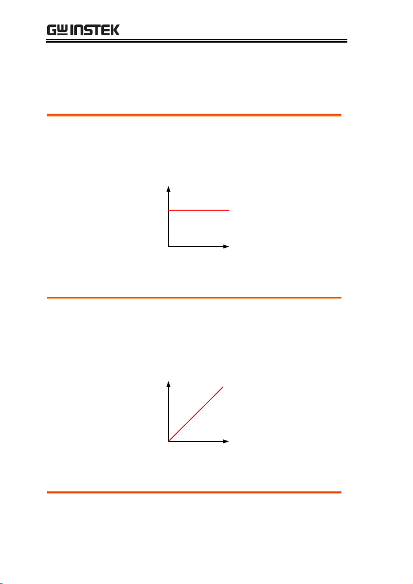
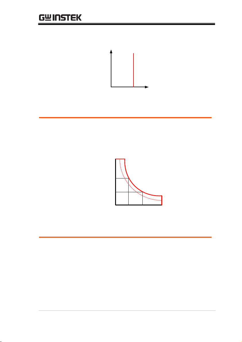
Background
With the operating mode of Constant Current, the
PEL-5000C Series electronic load will sink a
current in accordance with the programmed value
regardless of the input voltage
CURRENT SETTING
LOAD
CURRENT
INPUT VOLTAGE
V
CC
Background
At Constant Resistance mode, the PEL-5000C
series electronic load will sink a current linearly
proportional to the load input voltage in
accordance with the programmed resistance
setting
RESISTANCE
SETTING
LOAD
CURRENT
INPUT VOLTAGE
V
I
Background
At Constant Voltage mode, the PEL-5000C series
electronic load will attempt to sink enough current
Operating Mode Description
CC Mode
CR mode
CV mode
14
until the load input voltage reaches the
programmed value
VOLTAGE
SETTING
LOAD
CURRENT
INPUT VOLTAGE
V
I
CP mode
Background
At Constant Power mode, the PEL-5000C series
electronic load will attempt to sink load power
(load voltage * load current) in accordance with
the programmed power.
POWER
SETTING
LOAD
CURRENT
INPUT VOLTAGE
V
I
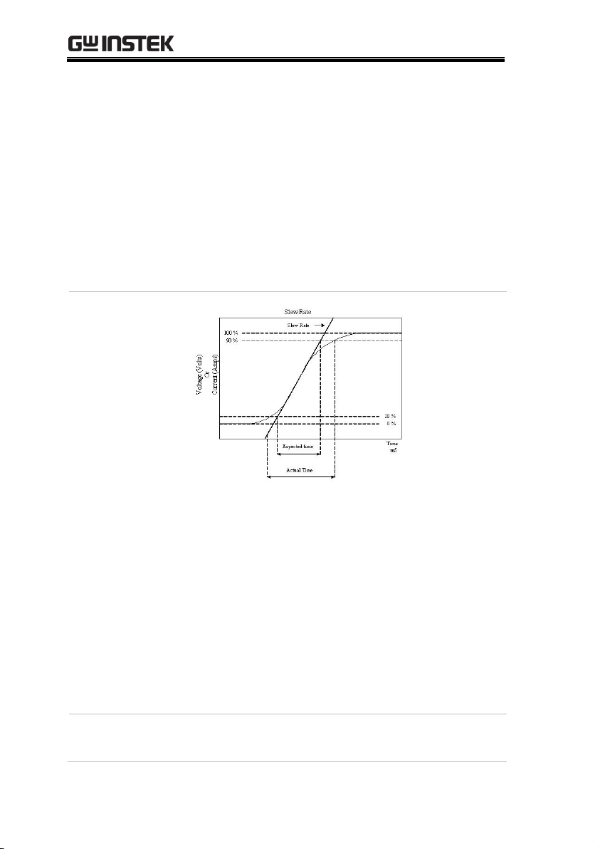
Background
Slew rate is defined as the change in current or
voltage over time. A programmable slew rate
allows for a controlled transition from one load
setting to another. It can be used to minimize
induced voltage drops on inductive power wiring,
or to control induced transients on a test device
(such as would occur during power supply
transient response testing).
In cases where the transition from one setting to
GETTING STARTED
Slew Rate
15
PEL-5000C User Manual
another is large, the actual transition time can be
calculated by dividing the voltage or current
transition by the slew rate. The actual transition
time is defined as the time required for the input to
change from 10% to 90% or from 90% to 10% of the
programmed excursion.
In cases where the transition from one setting to
another is small, the small signal bandwidth (of the
load) limits the minimum transition time for all
programmable slew rates. Because of this
limitation, the actual transition time is longer than
the expected time based on the slew rate.
Rise Time
Transition
Limitation
Therefore, both minimum transition time and slew
rate must be considered when determining the
actual transition time. Following detail description
is excluding in specification sheet.
The minimum transition time for a given slew rate
as about a 30% or greater load change, the slew
rate increases from the minimum transition time to
the Maximum transition time at a 100% load
change. The actual transition time will be either the
minimum transition time, or the total slew time
(transition divided by slew rate), whichever is
longer.
Example
PEL-5012C-600-840 600V/840A/12000W (CCH CCL >840Ax 30%)
16

GETTING STARTED
Use the following formula to calculate the
minimum transition time for a given slew rate min
transition time=252A/slew rate (in amps/second).
10.5uS (252A/24) x 0.8(10%~90%) =8.4uS
Use the following formula to calculate the
maximum transition time for a given slew rate max
transition time=840/slew rate (in amps/second).
35uS (840A/24) x 0.8(10~90%) = 28uS
EX. CCH=168A, CCL=0A Slew Rate =24A, the
expected time is 5.6uS but the actual Transition
Time Will be limited to 4.8Us.
7uS (168/24 x 0.8(10%~90%) = 5.6uS
Note
When CC mode rang1 slew rate, CCL setting at least
0.1% larger than the specification.
Background
Along with static operation the PEL-5000C series
electronic load are built with a dynamic mode for
operation in Constant Current (CC), Constant
Resistance (CR) or Constant Power (CP). This
allows the test engineer to simulate real world
pulsing loads or implement a load profile that
varies with time.
A dynamic waveform can be programmed from
the front panel of the PEL-5000C electronic load.
The user would first set a High and low value of
load current using the Level button. The Dynamic
Setting then allows for the rise and fall time
between these 2 current values to be adjusted. The
time period that the waveform is high (Thigh)
along with the time period that the waveform is
low (Tlow) can also be set.
Dynamic Waveform Definition
17

PEL-5000C User Manual
Dynamic Wave
form
I
V
LOAD
CURRENT
RISE
SLEW RATE
HIGH LOAD
LOAD
LOW LOAD
LEVEL
T
HIGHTLOW
FALL SLEW RATE
The dynamic waveform can also be set up via the
optional computer interface. Dynamic waveform
settings made from the front panel of the load
module can also be saved in the memory of the
PEL-5000C series Electronic Load. For the
store/recall procedure and the computer
command set please refer to the relevant operating
manual for the PEL-5000C series Electronic Load.
Further dynamic waveform definitions are:
The period of dynamic waveform is Thigh +
Tlow
The dynamic frequency = 1 /( Thigh + Tlow )
The duty cycle = Thigh / ( Thigh + Tlow )
Example 1
PEL-5000C series, Dynamic up to 50 KHz
frequency
Dynamic highest frequency 50 KHz = 0.02ms=20us
Setting THIGH=10 uS, TLOW=10uS,
THIGH+TLOW=20uS
CCH-CCL/SR≦10uS
Setting CCH=30A, CCL=10A
(30-10)/2.5A/uS≦10 uS
8 uS≦10 uS ,Compliance with frequency 50KHz
Example 2
Setting THIGH=10 uS, TLOW=10uS,
THIGH+TLOW=20uS
CCH-CCL/SR≦10uS
18

GETTING STARTED
Setting CCH=50A, CCL=0A
(50-0)/2.5A/uS=20uS, 20uS>10uS, It's not
compliance the frequency 50 KHz
The analogue programming input also provides a
convenient method of implementing a dynamic
waveform.
19
PEL-5000C User Manual
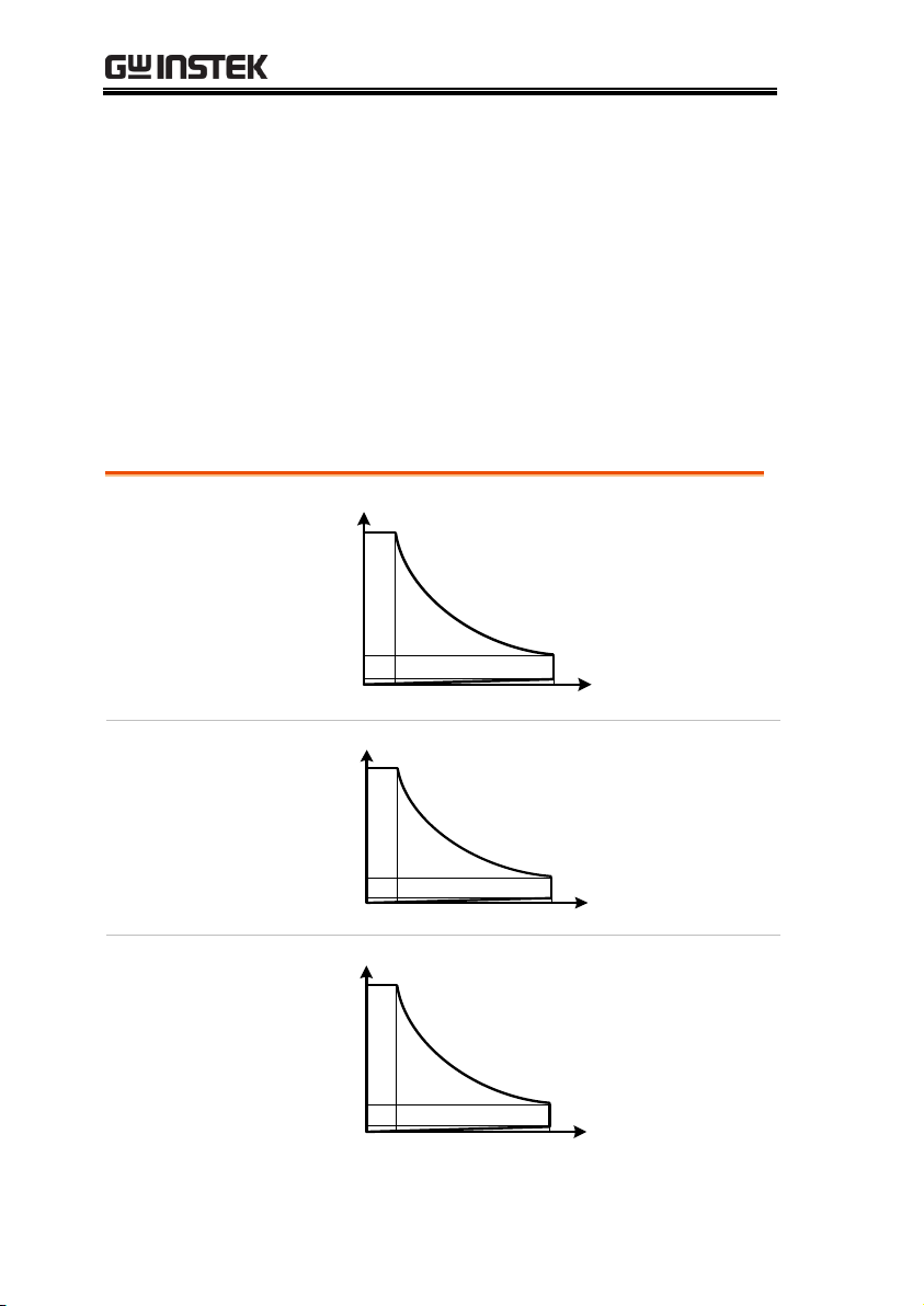
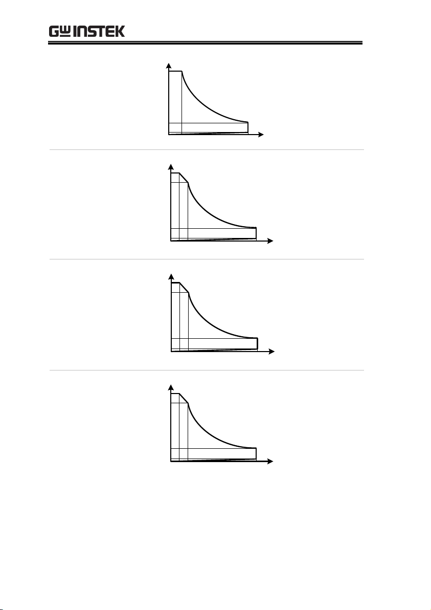
PEL-5006C-150-600
power contour
150V
10V
600A
40A
6KW
Power Curve
Current
0.7V
Voltage
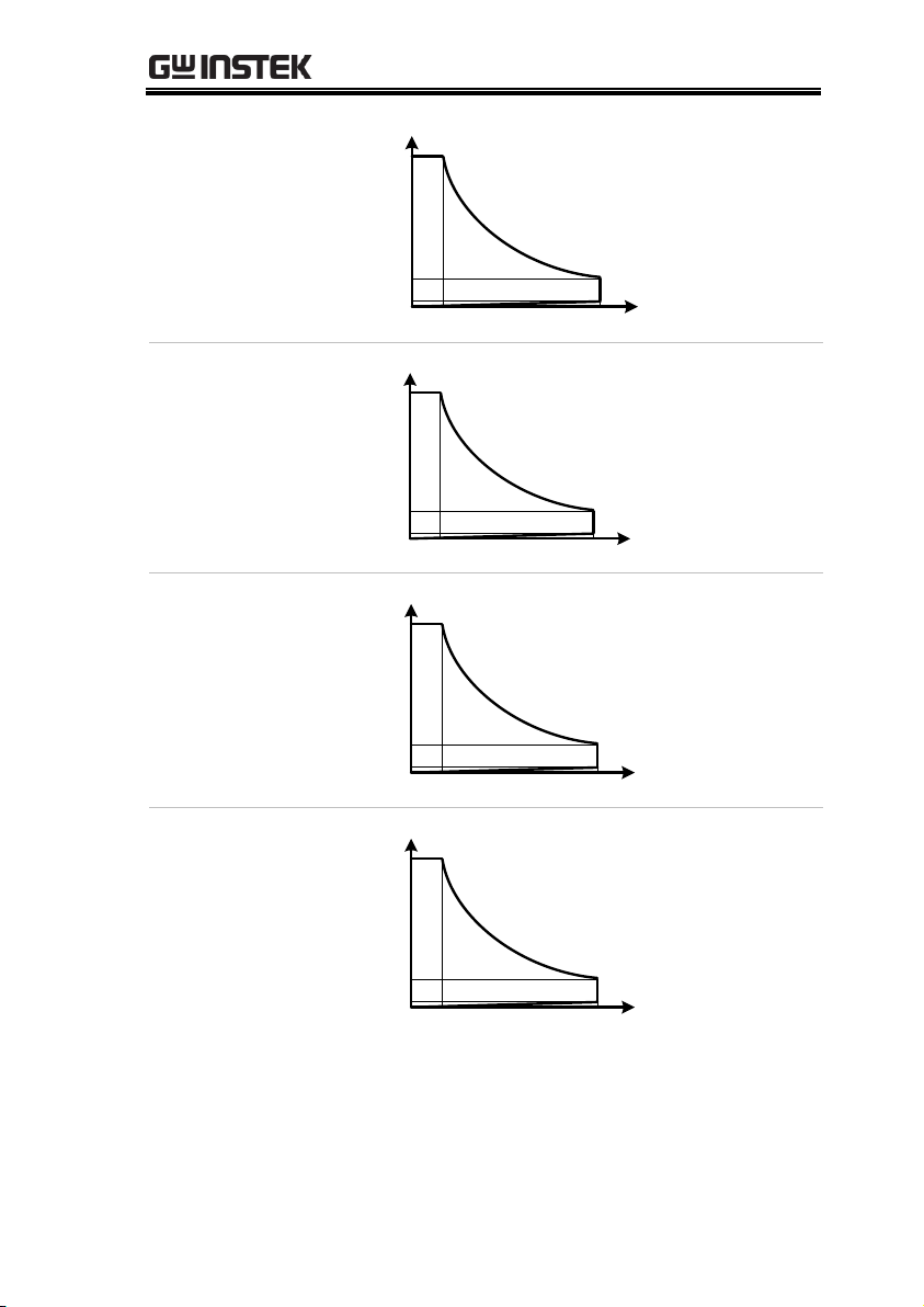
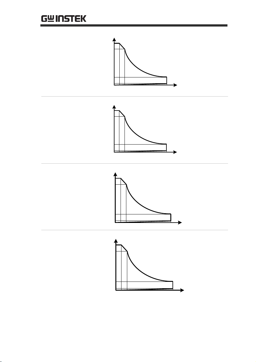
PEL-5008C-150-800
power contour
150V
10V
800A
53.3A
8KW
Power Curve
Current
Voltage
0.7V
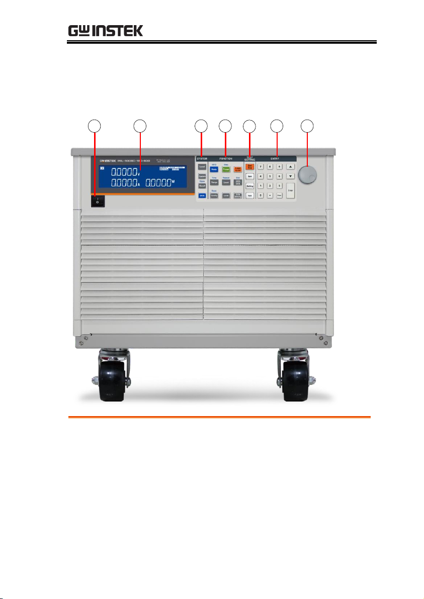
PEL-5010C-150-1000
power contour
150V
10V
1000A
66.6A
10KW
Power Curve
Current
Voltage
0.7V
Operating Area
The PEL-5000C series electronic load can be operated for manual
and GPIB operation.
The PEL-5000C series high power electronic Load can be controlled
locally at the front panel or remotely via computer over the
GPIB/RS232/USB/LAN. Constant current (CC) mode, constant
resistance (CR) mode, and constant voltage (CV) mode and
constant power (CP) mode. The wide range dynamic load with
independent rise and fall current slew rate and analog
programming input with arbitrary wave-form input is available in
Constant Current mode.
20

GETTING STARTED
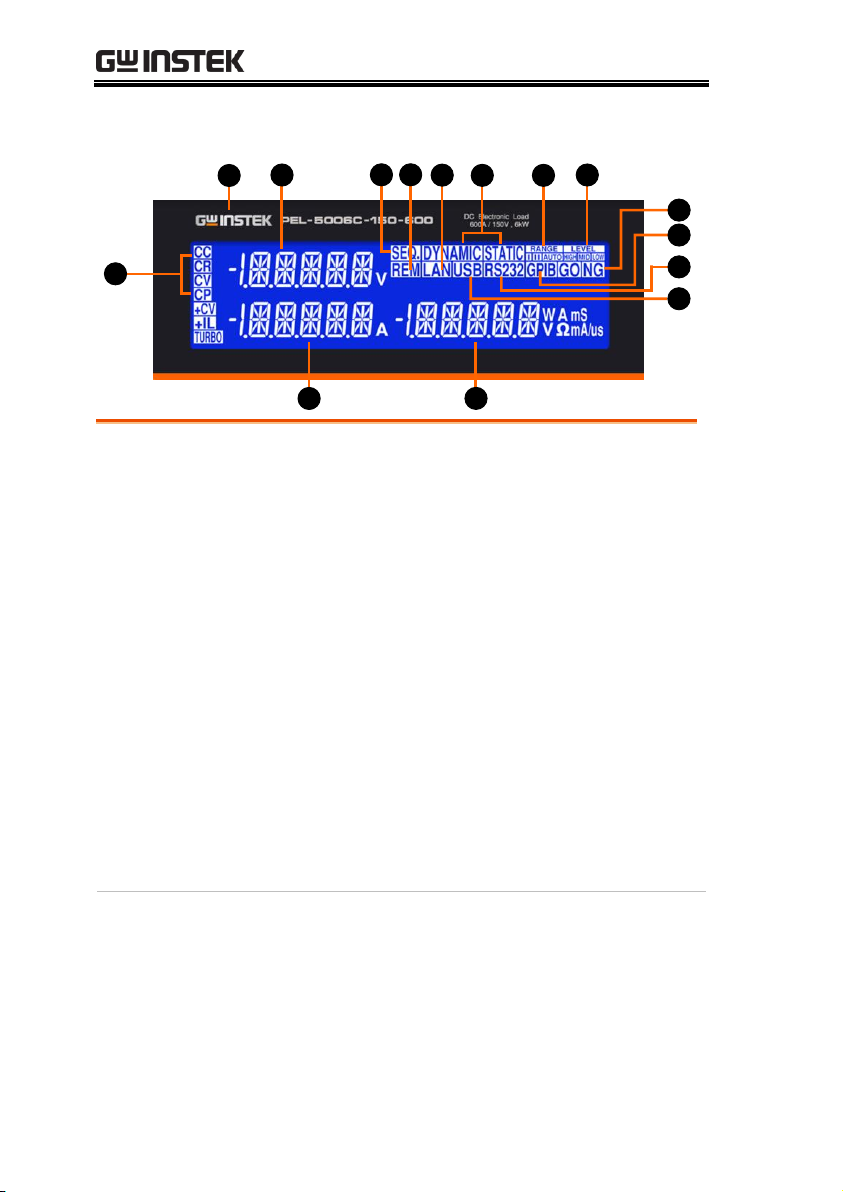
PEL-5012C-150-1200
power contour
150V
10V
1200A
80A
12KW
Power Curve
Current
Voltage
0.7V
PEL-5015C-150-1500
power contour
150V
10V
1500A
100A
15KW
Power Curve
Current
Voltage
0.7V
PEL-5018C-150-1800
power contour
150V
10V
1800A
120A
18KW
Power Curve
Current
Voltage
0.7V
PEL-5020C-150-2000
power contour
150V
10V
2000A
133.3A
20KW
Power Curve
Current
Voltage
0.7V
21

PEL-5000C User Manual
PEL-5024C-150-2000
power contour
150V
12V
2000A
160A
24KW
Power Curve
Current
Voltage
0.7V
PEL-5006C-600-420
power contour
600V
14.29V
420A
10A
6KW
Power Curve
Current
Voltage
10V
PEL-5008C-600-560
power contour
600V
14.29V
560A
13.33A
8KW
Power Curve
Current
Voltage
10V
PEL-5010C-600-700
power contour
600V
14.29V
700A
16.66A
10KW
Power Curve
Current
Voltage
10V
22
GETTING STARTED
PEL-5012C-600-840
power contour
600V
14.29V
840A
20A
12KW
Power Curve
Current
Voltage
10V
PEL-5015C-600-1050
power contour
600V
14.29V
1050A
25A
15KW
Power Curve
Current
Voltage
10V
PEL-5018C-600-1260
power contour
600V
14.29V
1260A
4.16A
18KW
Power Curve
Current
Voltage
10V
PEL-5020C-600-1400
power contour
600V
14.29V
1400A
33.33A
20KW
Power Curve
Current
Voltage
10V
23
PEL-5000C User Manual
PEL-5024C-600-1680
power contour
600V
14.29V
1680A
40A
24KW
Power Curve
Current
Voltage
10V
PEL-5006C-1200-240
power contour
1200V
25V
240A6A
6KW
Power Curve
Current
Voltage
15V
1000V
3A
PEL-5008C-1200-320
power contour
1200V
25V
320A8A
8KW
Power Curve
Current
Voltage
15V
1000V
4A
PEL-5010C-1200-400
power contour
1200V
25V
400A
10A
10KW
Power Curve
Current
Voltage
15V
1000V
5A
24
GETTING STARTED
PEL-5012C-1200-480
power contour
1200V
25V
480A12A
12KW
Power Curve
Current
Voltage
15V
1000V
6A
PEL-5015C-1200-600
power contour
1200V
25V
600A15A
15KW
Power Curve
Current
Voltage
15V
1000V
7.5A
PEL-5018C-1200-720
power contour
1200V
25V
720A
18A
18KW
Power Curve
Voltage
15V
1000V
9A
PEL-5020C-1200-800
power contour
Current
1200V
25V
800A20A
20KW
Power Curve
Voltage
15V
1000V
10A
25

PEL-5000C User Manual
PEL-5024C-1200-960
power contour
1200V
25V
960A24A
24KW
Power Curve
Current
Voltage
15V
1000V
12A
26
GETTING STARTED
3 4
5
6 721
1
Power switch
2
LCD Multi-function display
3
System keys
4
Function keys
5
Test function keys
6
Number keypad
7 Knob setting
Appearance
Front Panel
27
LCD Display
1
3
6 7
9
13
2
15
8
14
4
5
12
9
10
11
1
Model number
and sink ranges
The model number along with maximum
voltage, current and power values are detailed
in this position at the top of the load front
panel.
2
Left 5 digit LCD
display
The 5 digit LCD display is a multi-function
display. The function of the display changes
depending whether the user is in NORMAL
mode or in a SHORT, OPP or OCP modes:
Status display:
When enter System Setting or AUTO
SEQUENCE, the display setting item.
Normal mode
The left 5 digit display displays the voltage
present at the load’s input terminals. The
value displayed will include the automatic
voltage compensation if the sense terminals
are also connected to the device under test
(DUT).
Note
If V-sense is set to “AUTO” and the sense leads
are connected to the DUT the losses need to be
approx. 700mV (PEL-5006C-150-600) before the
display compensates for the voltage loss.
If V-sense is set to “ON” and the sense terminals
are connected to the DUT the load will check and
compensate for all voltage drops.
PEL-5000C User Manual
28

GETTING STARTED
Test mode
If the SHORT, OPP or OCP buttons are
pressed the left display will show a text
Message that correlates with the selected test
function.
SHORT test selected: left display will show
“Short”.
OPP test selected: left display will show
“OPP”.
OCP test selected: left display will show
“OCP”.
During the test the left display will show the
load Input voltage.
3
SEQ. indicator
When entering AUTO SEQUENCE mode,
LCD indicator will light up.
4
REM LCD
Indicator
If the REMOTE LCD Indicator is illuminated
this means that the unit is operating remotely
via one of the optional interfaces. While
REMOTE is lit it is not possible to make
settings manually at the front panel. The
LOCAL button on the mainframe can be used
to revert back to front panel control. When the
unit is operating from the front panel the
REMOTE LCD will not be illuminated.
5
LAN mode Lit
It is LAN interface inside.
6
DYN/STA LED
Indicator
The DYN button allows the user to switch
between DYNAMIC operation and STATIC
operation. Dynamic operation is only possible
in constant current (CC) or Constant power
(CP) mode only. The LED next to the DYN
button will become lit When DYNAMIC
operation is selected. If you are in constant
resistance (CR) or Constant voltage (CV) mode
pressing the DYN button will have no effect.
7
Rang LED
Indicator
The PEL-5000C series Load Module features 2
setting ranges for CC, CR, CV & CP operation.
This allows improved resolution for setting
29

PEL-5000C User Manual
low values. When left in the default AUTO
mode the changeover between ranges is
automatic depending on the setting value
entered.
If desired the RANGE button can be pressed
to force the unit to operate only in ANGE II.
This is signaled by the accompanying LED
becoming lit.
Note
That it is only possible to force RANGE II in CC
mode.
8
Level LED
Indicator
or Low load value. The setting value changes
between current, resistance, voltage or power
depending whether CC, CR, CV or CP mode
has been selected. If the LED is lit then the
High level value setting has been enabled. If
the LED is not lit then the low load level can
be set using the rotary switch in combination
with the arrow keys.
High and low load levels during operation.
only) the preset high and low levels are used
to define the dynamic waveform.
Note
The converse is also true in that the High level
cannot be set below the low level.
9
NG LCD
Indicator
The user can adjust upper and lower limits for
voltage, current and power within the
CONFIG menu and turn the NG Indicator
ON. If a voltmeter, ammeter or wattmeter
measurement is outside these set limits then
the NG indicator will illuminate.
10
GPIB mode Lit
It is GPIB inside. The LCD will be lit GPIB
when Power ON. If PEL-5000C series is
controlled by GPIB through PC, the GPIB will
30

GETTING STARTED
be lit.
11
RS232 mode Lit
It is RS232 inside. The LCD will be lit RS232
when Power ON. If PEL-5000C series is
controlled by RS232 through PC, the RS232
will be lit.
12
USB mode Lit
It is USB interface inside.
13
The right 5 digit
displays
The right 5 digit displays also changes
function depending if the unit is in normal
mode or one of the setting menus has been
activated.
Display System Setting state or AUTO
SEQUENCE setting value.
Normal mode
In normal mode the right 5 digit displays
shows the power consumption in Watts (W).
Setting mode
The right display together with the rotary
adjustment knob is used to set values.
The value changes according to the setting
function that is active. The middle LCD
provides a text message to tell the user which
part of the setting menu is active.
14
Middle 5 digit
LCD display
function depending if the user is in normal
mode or has entered a setting menu
Status display:
When enter System Setting or AUTO
SEQUENCE, the display setting item.
Normal mode
In normal mode the middle LCD display
functions as a 5 digit ammeter. The 5 digit
DAM shows the load current flowing into the
DC load when the Load is ON.
Setting mode
If CONFIG, LIMIT, DYN, SHORT, OPP or
OCP buttons are pressed the middle LCD
show a text message according to the setting
function it is in. Each subsequent press of the
31

PEL-5000C User Manual
button moves the display to the next available
function.
The sequence of each setting menu is detailed
below
CONFIG:
Sequence is “SENSE” ”LDon” “LDoff”
”POLAR” “MPPT” ”CPRSP”
”AVG”
LIMIT:
Sequence is “Add.CV” “V_Hi”
”V_Lo” ”I_Hi” “I_Lo” ”W_Hi”
”W_Lo” “NG”
DYN setting:
Sequence is “T-Hi” “T-Lo” “RISE”
“FALL”
SHORT:
Sequence is “PRESS” “TIME” “V_Hi”
“V_Lo”
OPP:
Sequence is “PSTAR” “PSTEP”
“PSTOP“ “Vth”
OCP:
Sequence is “ISTAR” “ISTEP”
“ISTOP" “Vth”
PRESET mode
The value of the setting entered on the right
display changes depending on the operating
MODE that has been selected
If CC mode is selected the right display
provides setting in amps "A".
If CR mode is selected the right display
provides setting in ohms “Ω”
If CP mode is selected the right display
provides setting in watts “W”.
If CV mode is selected the right display
provides setting in volts “V”.
LIMIT
Each press of the LIMIT button changes the
32

GETTING STARTED
middle LCD text. The sequence and the
corresponding setting value shown on the
bottom display is as follows:
Set CC + CV or CP + CV upper limit voltage,
the middle of the display show “Add.CV”,
right display set value, the unit is V.
V_Hi (left limit voltage) displays the set
value in volts “V”
V_Lo (right limit voltage) displays the set
value in volts “V”
I_Hi (left limit current) displays the set
value in amps “A”
I_Lo (right limit current) displays the set
value in amps “A”
W_Hi (left limit power) displays the set
value in watts “W”
W_Lo (right limit power) displays the set
value in watts “W”
NG displays whether the NG flag is set to
“ON” or “OFF”.
DYN Setting
Each press of the DYN setting button changes
the text on the middle LCD. The sequence and
the corresponding setting value shown on the
bottom display are as follows:
T-Hi (time high) displays the set value in
milliseconds “ms”
T-Lo (time low) displays the set value in
milliseconds “ms”
Rise (current rise time/slew rate) displays
the set value in “A/us” or “A/ms”
Fall (current fall time/slew rate) displays the
set value in “A/us” or “A/ms”
CONFIG
Each press of the CONFIG button changes the
right upper LCD Text.
The sequence and the corresponding setting
33

PEL-5000C User Manual
value shown on the bottom displays are as
follows:
SENSE can be set to “AUTO” or “ON”
LDon (load ON voltage) displays the set
value in volts “V”
LDoff (load OFF voltage) displays the set
value in volts “V”
POLAR (load polarity) can be set
to ”+LOAD” or “-LOAD”
MPPT (Maximum power point tracking)
BATT1 (Battery Discharge)
BATT2 (Battery Discharge)
BATT3 (Battery Discharge)
CPRSP (CP RESPONSE)
AVG
SHORT test
This allows the parameters of the short test to
be set up.
Each press of the SHORT button moves the
setting function. The sequence of the short test
along with the setting value is as follows:
Short Press Start (pressing the
START/STOP button starts the test).
TIME shows the duration of the SHORT
test. “CONTI”, on the bottom display
indicates continuous. Time can be adjusted
in “ms”.
V-Hi (voltage high threshold) displays the
set value in volts “V”
V-Lo (voltage low threshold) displays the
set value in volts “V”
When the test is started the right display will
show RUN. When the test has finished the
right display will show END.
OPP test
This allows the parameters of the over power
protection test to be set up. Each press of the
34

GETTING STARTED
OPP button moves the setting function. The
sequence of the OPP test along with the
setting value is as follows:
OPP Press Start (pressing the red
START/STOP button starts the test)
PSTAR (power start point) right display
provides setting in watts “W”
PSTEP (power steps) right display
provides setting in watts “W”
PSTOP (power stop point) right display
provides setting in watts “W”
VTH (voltage threshold) right display
provides setting in volts “V”
When the test is started the right display will
show the power value being taken by the load.
If the Device Under Test is able to supply the
load according to the values set then the right
display will show PASS and the right display
will show the maximum power taken during
the OPP test. If during the test, OTP is
displayed the over temperature protection has
been engaged. Similarly if OPP is shown on
the display the over power protection has
been activated.
OCP test
This allows the parameters of the over current
protection test to be set up. Each press of the
OCP button moves the setting function.
The sequence of the OCP test along with the
setting value is as follows:
OCP Press Start (pressing the red
START/STOP button starts the test)
ISTAR (current start point) right display
provides setting in amps “A”
ISTEP (current steps) right display
provides setting in amps “A”
ISTOP (current stop point) right display
35

PEL-5000C User Manual
provides setting in amps “A”
VTH (voltage threshold) right display
provides setting in volts “V”
When the test is started the right display will
show the current value being taken by the
load. If the Device under Test is able to supply
the load according to the values set then the
middle display will show PASS and the right
display will show the maximum current taken
during the OCP test. If during the test, OTP is
displayed the over temperature protection has
been engaged. Similarly if OPP is shown on
the display the over power protection has
been activated.
10
Mode and
Indicators
There are four operating modes that can be
selected by pressing the “MODE” key on the
PEL-5000C series Electronic Load module. The
sequence is Constant Current (CC), Constant
Resistance (CR), Constant Voltage (CV), and
Constant Power (CP). Each time the "MODE"
key is pressed the operating mode is changed.
The actual operating mode selected is
indicated on the left hand side of the LCD.
OPP test
This allows the parameters of the over power
protection test to be set up. Each press of the
OPP button moves the setting function. The
sequence of the OPP test along with the
setting value is as follows:
OPP Press Start (pressing the red
START/STOP button starts the test)
PSTAR (power start point) right display
provides setting in watts “W”
PSTEP (power steps) right display
provides setting in watts “W”
PSTOP (power stop point) right display
provides setting in watts “W”
VTH (voltage threshold) right display
36

GETTING STARTED
provides setting in volts “V”
When the test is started the right display will
show the power value being taken by the load.
If the Device Under Test is able to supply the
load according to the values set then the right
display will show PASS and the right display
will show the maximum power taken during
the OPP test. If during the test, OTP is
displayed the over temperature protection has
been engaged. Similarly if OPP is shown on
the display the over power protection has
been activated.
37

PEL-5000C User Manual
Function keys description ..................................... 39
Test keys description ............................................ 53
System keys description ........................................ 68
Test keys description ............................................ 77
FUNCTION DESCRIPTION
38

FUNCTION DESCRIPTION
Mode and CC,
CR, CP, CV
Indicator
Mode
SEQ
There are four operating modes. These can
be selected in turn by pressing the
“MODE” key on the PEL-5000C series
Electronic Load module. The sequence is:
(CC) Constant Current
(CR) Constant Resistance
(CP) Constant Power
(CV) Constant Voltage
The appropriate LCD will illuminate
according to the operating mode is
selected.
Load key and
LED
indicators
Load
On/Off
The input to the PEL-5000C Series
electronic load can be switched ON/OFF
by using the “LOAD” button. Indication of
the ON/OFF state is provided by
illumination of the button.
LOAD button lit = LOAD ON (load sinks
according to the preset values)
LOAD button unlit = LOAD OFF (the load
does not sink current)
Turning the LOAD OFF does not affect the
preset values. When the LOAD ON state is
enabled the unit will revert to sinking
according to the preset values.
When the Load ON/OFF key is operated
Function keys description
39

PEL-5000C User Manual
the current taken by load will follow the
RISE or FALL with time according to the
preset rate. The current RISE and FALL
times can be adjusted in the DYN Setting
button of the front panel.
In addition to the LOAD ON/OFF
function the user can also adjust the
voltage level at which the unit will
automatically start or stop sinking energy.
The adjustable LDon and LDoff voltage
levels are found within the CONFIG
menu.
Please note that the LDoff level cannot be set
higher than the LDon level.
Preset key and
LED
indicators
Preset
If the PRESET key is pressed the button
will become lit indicating that the PRESET
mode has been accessed. The lowest 5 digit
display will change from showing the
power consumption in watts to displaying
the value to be preset. The value that can
be programmed changes according to the
operating mode that has been selected.
Constant Current (CC) mode:
The A and B levels of load current can
be preset at right lower 5 digit LCD.
The “A” LED will be lit indicating the
setting value is amps.
Constant Resistance (CR) mode:
The A and B levels of load resistance
can be preset on the right lower 5 digit
LCD. The “Ω” LED will be lit indicating
the setting value is ohms.
Constant Voltage (CV) mode:
The A and B levels of load voltage can
be preset on the right lower 5 digit
LCD. The “V” LED will be lit indicating
the setting value is volts.
Constant Power (CP) mode:
40

FUNCTION DESCRIPTION
The A and B levels of load power can
be preset on the right lower 5 digit
LCD. The “W” LED will be lit
indicating the setting value is watts.
Dynamic mode (CC, CR or CP modes
only):
Preset key
DYN
STA
Each press of the DYN button cycles
through the dynamic load settings. The
DYN settings are used in conjunction with
the High and Low levels of load current to
define the dynamic waveform. Each press
of the DYN button switches from T_Hi
(time high), to T_Lo (time low), to Rise
time and then to fall time. The middle LCD
shows the section of the dynamic
waveform which is programmed with the
rotary knob and read from the right
display. The “ms” LED shows that the
settings are programmed in milliseconds.
Range key
Range
The PEL-5000C series Load Module
features 2 setting ranges for CC, CR, CV &
CP operation. This allows improved
resolution for setting low values. When left
in the default AUTO mode the changeover
between ranges is automatic depending on
the setting value entered.
If desired the RANGE button can be
pressed to force the unit to operate only in
RANGE II. This is signaled by the
accompanying LED becoming lit.
Note
It is only possible to force RANGE II in CC
mode.
41

PEL-5000C User Manual
Level key
Level
The LEVEL button is used to program a
High or Low load value. The setting value
changes between current, resistance,
voltage or power depending whether CC,
CR, CV or CP mode has been selected. If
the LED is lit then the High level value
setting has been enabled. If the LED is not
lit then the low load level can be set using
the rotary switch in combination with the
arrow keys.
In STATIC mode the user can switch
between High and low load levels during
operation.
In DYNAMIC operation (CC & CP modes
only) the preset high and low levels are
used to define the dynamic waveform.
Note
The low level setting cannot exceed the high
level. The converse is also true in that the
High level cannot be set below the low level.
Limit key
Limit
The LIMIT button allows the user to set
left and right thresholds for voltage,
current or power. These threshold settings
are used in conjunction with the NG
function to flag when the load is operating
outside the desired limit.
Each press of the LIMIT key enables a
different value to be entered. On first press
of the LIMIT key the button will illuminate
Add.CV will be displayed on the middle
LCD. The setting is made with the rotary
knob and can be read from the right LCD
during setting.
The setting sequence is shown below:
Add.CV (CC+CV or CP+CV upper
limit)
V_Hi (DVM upper limit)
42

FUNCTION DESCRIPTION
V_Lo (DVM lower limit)
I_Hi (DAM upper limit)
I_Lo (DAM lower limit)
W_Hi (DWM upper limit)
W_Lo (DWM lower limit)
NG OFF/ON (No Good Flag)
LIMIT setting function OFF
The engineering unit is “V”, “A” or “W”
depending on the threshold LIMIT being
set.
Setting CC+CV or CP+CV upper limit
voltage, Middle 5 digit LCD
display ”Add.CV”, right 5 digit LCD
display the unit is “V” ,The Add.CV set
range from 0.00 V to 600.00V step 0.01V by
rotating the Setting knob.
43

PEL-5000C User Manual
Setting upper limit voltage VH , Middle 5
digit LCD display “V-Hi”, right 5 digit
LCD display the unit is “V” ,The V-Hi set
range from 0.00 V to 600.00V step 0.01V by
rotating the Setting knob.
Setting lower limit voltage VL, the right
upper 5 digit monitor display ”V-Lo” and
right lower monitor display lower limit of
the voltmeter with the unit as “V” ,The VLo set range from 0.00 V to 600.00V step
0.01V by rotating the Setting knob.
Setting upper limit current IH , the right
upper 5 digit monitor display ”I-Hi” and
right lower monitor display upper limit of
the voltmeter with the unit as “A”, the I-Hi
set range from 0.000 A to 840.00A step
0.0001A by rotating the Setting knob.
Setting lower limit current IL , the right
upper 5 digit monitor display ”I-Lo” and
right lower monitor display lower limit of
the voltmeter with the unit as “A”, the I-Lo
set range from 0.000 A to 840.00A step
0.01A by rotating the Setting knob.
44

FUNCTION DESCRIPTION
Setting upper limit power WH, the right
upper 5 digit monitor display ”W-Hi” and
right lower monitor display upper limit of
the voltmeter with the unit as “W”, the WHi set range from 0 W to 12000W step 1W
by rotating the Setting knob.
Setting lower limit power WL, the right
upper 5 digit monitor display ”W-Lo” and
right lower monitor display lower limit of
the voltmeter with the unit as “W”, the WLo set range from 0 W to 12000W step 1W
by rotating the Setting knob.
Setting NG ON/OFF, When exceed VH,
VL, IH, IL, WH, WL One of these whether
NG on LCD display.
Limit
CC mode, press limits key to set the V-Hi
and V-Lo voltage upper and lower limits
of the GO / NG.
Go
NG
NG
Current
Voltage
Load Current
Low
High
Limit
CC Dynamic Mode, press key to set the
Level Hi and Level Low voltage upper and
lower limits of the GO / NG.
45

PEL-5000C User Manual
Go
NG
NG
Current
Voltage
Level Low
Low
High
Level Hi
Limit
CR mode, press limits key to set the V-Hi
and V-Lo voltage upper and lower limits
of the GO / NG.
Go
NG
NG
Load Current
Low
High
Load input Voltage
Resistance
Limit
CV mode, press limits key to set the I-Hi
and I-Lo Current upper and lower limits of
the GO / NG.
Load lnput Voltage
Go
NG
NG
Load Current
Low
High
Voltage
Limit
CP mode, press limits key to set the W-Hi
and W-Lo power upper and lower limits of
the GO / NG.
46

FUNCTION DESCRIPTION
DYN setting
key
DYN
Setting
The DYN button allows the user to define
the timings of the dynamic load
Waveform. Firstly the high and low levels
of load current will need to be set via the
LEVEL switch. The RISE and FALL times
between the low load current and the high
load current along with the TIME the
waveform is HIGH and the TIME LOW
can is set via the DYN menu.
Each press of the DYN key enables a
section of the DYNAMIC waveform to be
set.
On first press of the DYN key the button
will illuminate and T-Hi will be displayed
on the middle LCD. The value is adjusted
with the rotary knob and can be read from
the right LCD during setting.
The setting sequence is shown below:
T_Hi (time the waveform is high)
T_Lo (time the waveform is low)
RISE (rise time)
FALL (fall time )
DYN setting function OFF
The time that the waveform is high
includes the rise time and is set in “ms”.
The time that the waveform is low
includes the fall time and is set in “ms”.
The RISE and FALL time is set in “A/μs”.
47

PEL-5000C User Manual
The actual engineering unit is shown on
the right of the Right 5 digit display
Press DYN setting key, LED will ON
setting level High Period, Middle 5 digit
LCD display will show “T-Hi” Right 5
digit LCD display will show setting value,
the unit is “ms”, The T-Hi set range from
0.010 ms to 9999 ms step 0.001ms by
rotating the setting knob.
There are four ranges from 0.010 ms to
9999 ms, the ranges are below:
Range 1:0.010ms~9.999ms
Range 2:10.00ms~99.99ms
Range 3:100.0ms~999.9ms
Range 4:10000ms~9999ms
48

FUNCTION DESCRIPTION
Setting level Low period, Middle 5 digit
LCD display will show “T-Lo”, right 5
digit LCD display will show setting value,
the unit is “ms” , the T-Lo set range from
0.010 ms to 9999 ms step 0.001ms by
rotating the Setting knob.
Setting rise time, Middle 5 digit LCD
display will show “RISE”, right 5 digit
LCD display will show setting value, the
unit is “A/μs”, the RISE time set range
from 0.672A/us to 42.840 A/us step
0.168A/us by rotating the Setting knob.
Setting fall time, Middle 5 digit LCD
display will show “FALL”, right 5 digit
LCD display will show setting value, the
unit is “A/μs” , the FALL time set range
from 0.672A/us to 42.840A/us step
0.168A/us by rotating the Setting knob.
Config key
Config
The CONFIG key allows the sense function
to engage automatically or switched ON.
The CONFIG key also enables the LOAD
to automatically turn ON/OFF when a
voltage level is reached. The polarity
symbol can also be switched via the
CONFIG menu.
Each press of the CONFIG key moves the
menu on one step. On first press of the
CONFIG key the button will illuminate
and EXTIN will be displayed on the Right
49

PEL-5000C User Manual
upper LCD. The value is adjusted with the
rotary knob and can be read from the right
LCD during setting. The setting sequence
is shown below:
SENSE (AUTO or ON)
LDon (Voltage at which LOAD turns
ON)
LDoff (Voltage at which LOAD turns
OFF)
POLAR (change polarity symbol)
MPPT
CPRSP
Exit CONFIG options
Note
The adjustable LDon (LOAD ON) voltage is valid for
CC, CR & CP operating modes. The adjusted LDon
voltage will not operate in CV mode.
The LDon (LOAD ON) voltage setting cannot be lower
than the LDoff (LOAD OFF) voltage. If 0V is required
for both LOAD ON and LOAD OFF make the LOAD
OFF adjustment first.
Set vsense and load input switching
methods, the middle of the 5 digit LCD
display will show “SENSE”, Right 5 digit
LCD display will show “AUTO” or “ON”.
50

FUNCTION DESCRIPTION
Set Load ON voltage, the middle of the 5
digit LCD display will show “LDon”,
Right 5 digit LCD display will show
setting value, the units is V, The Load ON
Voltage set range from 0.8V to 100.0V step
0.4V by rotating the setting knob. If the
load is greater than the input voltage Load
ON voltage setting, the Electronic load
current begin to load on.
Note
CC/CR/CP MODE is controlled by Load ON voltage, CV
MODE is not controlled by Load ON voltage.
Set Load OFF voltage, the middle of the 5
digit LCD display will show “LDoFF”,
Right the 5 digit LCD display will show
settings value, the units is V, The Load
OFF Voltage set range from 0.0V to 99.00V
step 0.01V by rotating The Setting knob.
If the load input voltage is less than Load
OFF setting voltage, the electronic load to
load off.
Set Load polarity, the middle of the 5 digit
LCD display will show “POLAR”, Right
the 5 digit LCD display will show “+
LOAD” or “-LOAD”, use the knobs and
key settings “+ LOAD” or “-LOAD”.
51

PEL-5000C User Manual
Set MPPT (Maximum power point
tracking) testing, the middle of the 5 digit
LCD display will show “MPPT”, Right the
5 digit LCD display “1000”, the MPPT
setting range from 1000mS to 60000mS.
Set CPRSP, the middle of the 5 digit LCD
display will show “CPRSP”, Right the 5
digit LCD display “0”, the CPRSP set
range from 0 to 4 steps 1 by rotating the
setting knob. Setting CP Mode reaction
speed, 0: Fast, 4: Slow.
Set AVG, the middle of the 5 digit LCD
display will show “AVG”, Right the 5 digit
LCD display “1”, the AVG setting range
from 1 to 64 steps 1 by rotating the setting
knob.
52

FUNCTION DESCRIPTION
Item, Setting
and Exit keys
Item
Setting
Exit
Item, Setting and Exit key for Test. There
are eight operating modes. These can be
selected in turn by pressing the “Item
“key. Press ITEM key enter setting mode,
ITEM LED light ON, the setting sequence
is shown below:
OCP
OPP
DISch
SURGE
Exit ITEM options
Test keys description
53

PEL-5000C User Manual
Setting Short
mode
The Setting key allows the parameters of a
SHORT circuit test to be entered. The
SHORT test will attempt to sink high
current up to the PEL-5000C series load
maximum current in order to check the
power source’s protection and behavior.
The test time can be adjusted and
threshold values for the High and low
voltage limits set.
Setting
Pressing the Setting key once will cause
the button to illuminate. The Message
“SHORT PRESS START” will be shown
across the 3 displays.
Setting
Each press of the SHORT key moves the
menu on one step. The left and Middle
LCDs show the currently selected test
parameter as text. The value is adjusted by
the rotary knob and can be read from the
right display during Setting.
The setting sequence is shown below:
SHORT PRESS START (pressing the
start/stop key starts test)
SHORT Time (CONTI = Continuous or
100ms to 10,000ms possible)
SHORT V_Hi (High voltage threshold
setting)
SHORT V_Lo (Low voltage threshold
setting
Exit SHORT test set-up
54

FUNCTION DESCRIPTION
Set the short test time, the LCD display
show “SHORT” on left 5 Digits LCD
display, shows “TIME” on middle 5 digits
LCD display, right 5 digit LCD
display ”CONTI”, the unit is “ms”.
TIME: Set the short test time, The LCD
display show “SHORT” on left 5 digits
LCD display, shows “TIME” on middle 5
digits LCD display the unit is “ms”, and
shows “CONTI” on right 5 digits LCD
display, the setting range is “CONTI”
means continue, 100mS to 10000mS step
100mS by clockwise rotate the setting
knob. The short test will be no time
limitation when setting to CONTI until
press “START/STOP” key to stop the
short test.
55

PEL-5000C User Manual
V-Hi : Short test voltage check upper
limitation setting, the LCD display shows
“SHORT” on left 5 digit LCD display,
Middle 5 digit LCD display ”V-Hi”, right 5
digit LCD display setting value, the unit is
“V”, The V-Hi setting range from 0.00V to
600.00V step 0.01V by rotating the setting
knob.
V-Lo : Short test voltage check lower
limitation setting, the Left 5 digit monitor
display the “SHORT” ,the middle 5 digit
monitor display the “V-Lo” and right
lower monitor display setting value, the
unit is “V”. The range is 0.01V to 600.00V.
Start
Stop
Once the test parameters have been
entered the test is started by pressing the
START/STOP button while the SHORT
PRESS START text is displayed. During
the test the bottom LCD will show run and
the actual short current will be displayed
on the right upper LCD.
Note
The message PASS END will be displayed if the
measured voltage levels stay within the V_Hi and
V_Lo threshold levels during the test.
The message FAIL END will be displayed if the
measured voltage levels fall outside the V_Hi and
V_Lo threshold levels during the test. The NG flag will
also illuminate.
If continuous short time is selected the test is ended
by pressing the red START/STOP button.
56

FUNCTION DESCRIPTION
OCP
parameters
setting
The OCP key allows the parameters of an
Over Current Protection test to be entered.
The OCP test will ramp up the load
current in steps to validate the Device
Under test’s (DUT) protection and
behavior. A voltage threshold level can be
set. If the voltage measured during the test
is lower than the set Threshold voltage
then the test will fail and the display will
signal OCP ERROR. Similarly a current
Threshold (I STOP) can be set. If the
measured Current reaches the I STOP
Threshold the test will be discontinued
and the OCP ERROR message will be
displayed.
Setting
Press the Setting key once will cause the
button to illuminate. The message “OCP
PRESS START” will be shown across the 3
displays.
Each press of the OCP button moves the
menu on one step. The Left and Middle
LCDs show the currently selected test
parameter as text. The value is adjusted by
the rotary knob and can be read from the
Right display during setting.
The setting sequence is shown below:
OCP VTH OCP PRESS START
(pressing the red start/stop key starts
test)
OCP I STAR (current starting point of
the OCP test)
OCP I STEP (value of incremental
current steps from I START)
OCP I STOP (the OCP test’s upper
current threshold
OCP Vth (the voltage threshold setting)
Exit OCP test set-up
57

PEL-5000C User Manual
ISTAR: setting the start current point, the
Left 5 digit monitor display the “OCP”, the
right upper 5 digit monitor display the
“ISTAR”, and right lower monitor display
setting value, the unit is “A”. The range is
0.001A to the full scale of the CC mode
specification. The setting is by rotating the
setting knob.
ISTEP: setting the increment step current
point, The LCD display shows ”OCP” on
Left 5 digit LCD display, Middle 5 digit
LCD display ”ISTEP”, right 5 digit LCD
display setting value, the unit is “A”. The
setting range is 0.01A to the full scale of
the CC mode specification. The setting is
by rotating the setting knob.
58

FUNCTION DESCRIPTION
ISTOP: setting the stop current point, The
LCD display shows “OCP” on Left 5 digit
LCD display, Middle 5 digit LCD display
“ISTOP”, right 5 digit LCD display setting
value, the unit is “A”, the setting range is
0.000A to the full scale of the CC mode
specification. The setting is by rotating the
setting knob.
Vth: Setting threshold voltage; The LCD
display shows “OCP” on left 5 Digit LCD
display, middle 5 digit LCD display “Vth”,
right 5 digit LCD Display setting value, the
unit is “V”, the setting range is 0.00V to the
full scale of the voltage specification. The
setting is by rotating the setting knob.
Start
Stop
Once the test parameters have been
entered the test is started by pressing the
red START/STOP button while the OCP
PRESS START text is displayed. During the
Test the middle LCD will show run and the
actual current being Taken will be
displayed on the Right LCD
Note
The message OCP ERROR will be displayed if the DUT
fails the test. The reasons for failure are due to one of the
following conditions:
(a) the voltage level of the DUT falls below the set
voltage threshold (OCP Vth)during the test
(b) The current taken from the DUT reaches the OCP I
STOP setting.
The message PASS will be displayed if the DUTs voltage
stays above the set threshold. Also to PASS the OCP test
the current taken from the DUT cannot equal the I STOP
59

PEL-5000C User Manual
setting.
If the DUT passes the OCP test the maximum current
taken during the test is displayed on the right LCD.
Upon PASS or OCP ERROR the test will automatically
stop. The red START/STOP button can be used during the
test to immediately cease operation.
OPP
parameters
setting
The OPP allows the parameters of an Over
Power Protection test to be entered. The
OPP test will ramp up the load power in
steps to validate the Device under test’s
(DUT) protection and behavior. A voltage
threshold level can be set. If the voltage
measured during the test is lower than the
set Threshold voltage then the test will fail
and the display will signal OPP ERROR.
Similarly a power threshold (P STOP) can
be set. If the measured power reaches the P
STOP threshold the test will be
discontinued and the OPP ERROR
message will be displayed.
Setting
Press the Setting key once will cause the
button to illuminate. The message “OPP
PRESS START” will be shown across the
displays.
60

FUNCTION DESCRIPTION
Each press of the OPP button moves the
menu on one step. The Left and Middle
LCDs show the currently selected test
parameter as text. The value is adjusted by
the rotary knob and can be read from the
Right display during Setting.
The setting sequence is shown below:
OPP PRESS START (pressing the red
start/stop key starts test)
OPP P STAR (power starting point of
the OPP test)
OPP P STEP (value of incremental
current steps from P START)
OPP P STOP (the OPP test’s upper
threshold power limit)
OPP Vth (the voltage threshold setting)
Exit OPP test set-up
PSTAR: setting the start power, the LCD
display shows “OPP” on left 5 digit LCD
display, middle 5 digit LCD
display ”PSTAR”, right 5 digit LCD
display setting value, the unit is “W”, the
setting range is 0.00W to the full scale of
the CP mode specification. The setting is
by rotating the setting knob.
61

PEL-5000C User Manual
PSTEP: setting the increment step power,
the LCD display shows “OPP” on left 5
digit LCD display, middle 5 digit LCD
display ”PSTEP”, right 5 digit LCD display
setting value, the unit is “W”, the setting
range is 0.00W to the full scale of the CP
mode specification. The setting is by
rotating the setting knob.
PSTOP: setting the stop power, the Left 5
digit monitor display the “OPP” ,the right
upper 5 digit monitor display the
“PSTOP”, and right lower monitor display
setting value, the unit is “W”. The range is
0.1W to the full scale of the CP mode
specification.
Vth : Setting threshold voltage; the Left 5
digit monitor display the “OPP” ,the right
upper 5 digit monitor display the “Vth”,
and right lower monitor display setting
value, the unit is “V”. The range is 0.00V to
the full scale of the voltage specification.
The setting is by rotating the setting knob.
Start
Stop
Once the test parameters have been
entered the test is started by pressing the
red START/STOP button while the OPP
RESS START text is displayed. During the
Test the middle LCD will show run and the
actual current being Taken will be
displayed on the Right LCD
62

FUNCTION DESCRIPTION
Note
The message OPP ERROR will be displayed if the DUT
fails the test. The reasons for failure are due to one of the
following conditions:
(c) the voltage level of the DUT falls below the set
voltage threshold (OPP Vth)during the test
(d) The current taken from the DUT reaches the OPP P
STOP setting.
The message PASS will be displayed if the DUTs voltage
stays above the set threshold. Also to PASS the OPP test
the current taken from the DUT cannot equal the I STOP
setting.
If the DUT passes the OPP test the maximum current
taken during the test is displayed on the right LCD.
Upon PASS or OCP ERROR the test will automatically
stop. The red START/STOP button can be used during the
test to immediately cease operation.
Battery
discharge
setting
Disch
Mode CC
Disch
Mode CP
DIsch the test function has 5 parameters,
“CC”, “VOLT.V”, “TIME.S”, “CAP.AH”
and CAP.WH parameters.
Press the Setting key to set stop discharge
voltage “VOLT.V”, Press again Setting key
to set stop discharge time “TIMES.S”.
Press Setting key again to stop discharge
capacity “CAP.AH” / “CAP.WH”.
63

PEL-5000C User Manual
Setting battery discharge CC mode, DISCH
CC, LCD show “DISch”, middle 5 digit
LCD display “CC”, setting range 0.00A to
full scale.
Setting stop discharge voltage STOP
“VOLT.V”, middle 5 digit LCD display
“VOLT.V”, right 5 digit LCD display
setting value, unit is V, STOP “VOLT.V”
setting range 0.00V to full scale.
Setting stop discharge time, setting STOP
“TIME.S”, middle 5 digit LCD display
“TIME.S”, right 5 digit LCD display setting
value, STOP “TIME.S” setting OFF to
99999, each setting knob and button
adjustment interval is 1.
64

FUNCTION DESCRIPTION
Setting stop discharge capacity, setting
STOP “CAP.AH”, middle 5 digit LCD
display “CAP.AH”,right 5 digit LCD
display setting value, STOP “CAP.AH”
setting range OFF to 19999.9, each setting
knob and button adjustment interval is 0.1.
Setting stop discharge capacity, setting
STOP “CAP.WH”, middle 5 digit LCD
“CAP.WH”, right 5 digit LCD display
setting value, STOP “CAP.WH” setting
range OFF to 19999.9, each setting knob
and button adjustment interval is 0.1.
Surge current
testing setting
SURGE sequence is shown below:
SURGE the test function has 4 parameters,
“SUR.I”, “NOR.I’, “TIME” and “STEP”
parameters.
Press the Setting key to set surge
current testing loading current value
“SUR.I”.
Press again Setting key to set normal
current testing loading current value
“NOR.I”.
Press Setting key again to set surge
current testing time “TIME”.
Press the Setting key again to set surge
current testing diminishing step current
setting value “STEP”.
65

PEL-5000C User Manual
Set SURGE testing surge current, unit is A,
setting range 0.00A to full scale.
Set SURGE testing normal current, unit is
A, setting range 0.00A to full scale.
Set SURGE time, unit is mS, setting range
10mS to 1000mS.
Set SURGE step, setting range 1 to 5.
Setting fig
explanation.
66

FUNCTION DESCRIPTION
Exit Key
Exit
Setting OCP / OPP / DISch / SURGE
during the setting process press Exit key to
exit setting item.
Start/Stop key
Start
Stop
The START/STOP key is used in
conjunction with the SHORT, OCP or OPP
test functions. It is used to START a test
according to the set parameters or to STOP
a test before PASS or FAIL is signaled.
Please refer to the preceding sections for
more information on the SHORT, OCP &
OPP tests.
67

PEL-5000C User Manual
Shift key
Shift
Shift key is used to switch the key to the
second function key.
System key
System
Press SYSTEM to set the argument, GPIB
address, RS232 BAUD- RATE, WAKE UP
and buzzer Alarm power ON/OFF and
Master/Slave control.
Local key
Local
Press Local key to exit REMOTE mode
System keys description
68

FUNCTION DESCRIPTION
Setting system
parameters
Set GPIB address, RS232 BAUD RATE,
WAKE UP, Buzzer ON/OFF
Set GPIB
address
System
First press SYSTEM key, the LCD display
shows GPIB on left 5 digit LCD display,
Middle 5 digit LCD display Addr, right 5
digit LCD display setting GPIB address of
the representative, Press UP, DOWN
buttons to adjust the GPIB address 1~30,
Key and then press ENTER, PEL-5000C
series GPIB Address value is saved, Press
system key four times to leave the GPIB
address configuration State.
Set RS232
BAUD RATE
System
X2
SYSTEM key first by the second, the LCD
display shows RS232 on left 5 digit LCD
display, Middle 5 digit LCD display baud,
right 5 digit LCD display setting BAUDRATE, Press UP, DOWN buttons to adjust
the value of BAUD RATE, Key and then
press ENTER, PEL-5000C series is saved
setting BAUD RATE, press system key
three times to leave the BAUD-RATE
setting state.
69

PEL-5000C User Manual
WAKE-UP
function
System
X3
This function is designed for auto setting
the load status and load level in turning on
the PEL-5000C series every time. SYSTEM
key first by the three, The LCD display
shows WAKE on left 5 digit LCD display,
Middle 5 digit LCD display UP, right 5
digit LCD display setting, Press UP,
DOWN buttons to adjust the 0~150.
Press ENTER key to be stored, press
system key two times to leave the WAKEUP setting state, If set to “0” means do not
call.
70

FUNCTION DESCRIPTION
Buzzer ON/
OFF
This is the test set automatically (AUTO
SEQUENCE) at the end, if it increases
buzzer function, if set to ON, Then when
the test result is PASS automatically when
the buzzer will call out, if the test result is
FAIL when the buzzer will call the second
tone.
System
X4
Setting method:
first by 4 Times SYSTEM key and the LCD
display shows SEQ on left 5 digit LCD
display, Middle 5 digit LCD display bEEP,
right 5 digit LCD display setting ON or
OFF, press UP DOWN key to adjust.
Note
Setting system parameters, if the input is required to use
the KEYPAD ENTER button to confirm, otherwise PEL5000C Series will not save the changes the settings.
Pass: Automatic test mode, no NG state, is the PASS.
Fail: Automatic test mode, any test if the NG then is the
FAIL.
Recall/ Store
key
Recall
Store
Recall/ Store load state settings
The function keys on the front panel of
PEL-5000C series mainframe are designed
for high testing throughput purpose. There
are 150 operation states or testing steps can
be store in the EEPROM memory of PEL5000C series electronic load respectively,
each state can store or recall the load status
and level for electronic load
simultaneously.
71

PEL-5000C User Manual
STORE
process
Recall
Store
to enter the storage state.
adjust, press the ENTER OK to save the
STATE.
RECALL
operation
Recall
Store
adjust.
In the electronic load front panel, set the
value that would call out the information
in accordance with re-setting.
AUTO
SEQUENCE
instructions
PEL-5000C series has AUTO SEQUENCE
function, PEL-5000C series to select the
state F1~F9 Automatic testing can be
edited, 16 steps each group can be set to
select 150 group of the STATE, within each
step can be set TEST TIME Units of 100 ms
range (0.1s ~ 9.9s).
Edit mode
Shift
Mode
SEQ
Press SHIFT key, press the SEQ. key to
enter the AUTO SEQUENCE mode, Press
UP, DOWN key to select EDIT, the LCD
display shows EDIT on left 5 digit LCD
display, Middle 5 digit LCD display FX,
“FX” means to Select the state F1-F9,Press
keypad key 1 ~ 9 choose F1 ~ F9.
72

FUNCTION DESCRIPTION
Press ENTER key, the LCD display
shows FX-XX on left 5 digit LCD
display, Middle 5 digit LCD display
STATE, right 5 digit LCD display
setting 1~150, “FX” means to select the
state F1-F9. “XX” means the test
STEP01-16, setting state value, press UP
and down key or keypad to adjust
setting.
Test time
setting
Press ENTER to set TIME value, press
UP, DOWN keys or KEYPAD to adjust
settings, range from 100 ms~9999ms.
Press ENTER key or SAVE key to finish
editing the action is set to repeat, if you
do not save the settings, press the EXIT
key to leave edit mode.
Setting repeat (REPEAT TEST) ,Press
UP and DOWN key or Keypad to
adjust setting 0~9999, Press ENTER
SAVE REPEAT Value, or press eXIT
key Exit EDIT MODE.
73

PEL-5000C User Manual
Store (Edit) mode operation flow chart
74

FUNCTION DESCRIPTION
Test mode
Press SHIFT key, press the SEQ. key to
enter the AUTO SEQUENCE mode,
Press UP, DOWN key to select TEST,
the LCD display shows tEST on left 5
digit LCD display, Middle 5 digit LCD
display FX, “FX” means to Select the
state F1-F9, Press keypad key 1 ~ 9
choose F1 ~ F9. When the press ENTER
to enter. The next automatic test Mode.
Test LCD will display "SXX", "XX" on
behalf of the test of STEP, if the test
result is NG, the LCD will show "NG"
(flashing) and suspension of the test,
this time users can test or ENTER key
to continue Press EXIT key to leave the
test mode, test mode by the (STEP01 TIME) then (SETP02 - TIME) until all
the steps done or press EXIT to leave
the test mode.
If all the test steps are OK, the test
result is PASS, LCD displays “PASS”;
test procedure if any of the NG, the test
result is FAIL,, LCD displays “FAIL”, if
the buzzer is set to ON, when the test
result is pass automatically when the
buzzer will call out, if the test result is
fail Buzzer will sound when the second
call.
When the test is completed, the user can
press the ENTER key again to test or EXIT
key to leave the test mode.
Example
Edit the 16 step test is completed, press
the TEST key, according to the order of
S01 ~ S16 test is complete LCD display
PASS.
75

PEL-5000C User Manual
Test mode operation flow chart
76

FUNCTION DESCRIPTION
Rotary Knob
and ARROW
Keys
The ROTARY knob and ARROW keys are used to
increase or decrease the set values.
Clockwise the rotary switch and up arrow key to increase the
setting values.
Anti-clockwise and down arrow key operation of the ROTARY
Knob decreases the setting value.
Keypad key: When using the
Keypad, please enter the
number, press the Enter key.
Clear KEY: Setting, press the
Clear key to clear the input
value.
Test keys description
77

PEL-5000C User Manual
Note
In CR mode, the up arrow key and clockwise operation of
the rotary Knob reduces the resistance.
In CR mode, the down arrow key & anti-clockwise
operation of the rotary Knob increases the resistance.
78

CONNECTION
Rear Panel ............................................................. 80
Connecting the I-monitor to an oscilloscope ......... 84
Master/Slave Instructions ..................................... 85
CONNECTION
79

Rear Panel
INPUT
ANALOG
I
MONITOR
CONTROL
MASTER / SLAVE
N L
WARNING
TO AVOID ELECTRIC SHOCK THE POWER CORD PROTECTIVE
DO NOT REMOVE COVERS.
250V FUSE OF THE SPECIFIED TYPE AND RATING.
FOR CONTINUED FIRE PROTECTION. REPLACE FUSE ONLY WITH
NO OPERATOR SERVICEABLE COMPONENTS INSIDE.
GROUNDING CONDUCTOR MUST BE CONNECTED TO GROUND.
REFER SERVICING TO QUALIFIED PERSONNEL.
SER. NO. LB
V
SENSE
LINE INPUT
BREAKER
MAX.
100 240VAC
47 63Hz
LOAD
MAX. MAX.
LOAD
150V 150V 150V
400VA MAX.
1
2
34
1
DC INPUT
Terminal
The positive (LOAD +) and negative (LOAD -)
power input terminals are clearly marked. DO
NOT confuse them with the smaller SENSE
terminals.
Please ensure that the voltage and current
rating of the DUT do not exceed the maximum
rating of the PEL-5000C Series load module
being used. Please also check the output
polarity of the DUT prior to connection and
testing.
The negative load terminal should be connected
to ground if testing a positive output power
supply. This is normally achieved when the
negative output of the power supply is
grounded.
Similarly if a power supply with a negative
output is to be tested then the positive load
terminal should be grounded. This is normally
achieved when the positive output of the power
supply under test is grounded.
PEL-5000C User Manual
80

CONNECTION
2
V-sense input
terminal
The V-sense terminals can be used to
compensate for a voltage drop in the load lines
between the power supply and the PEL-5000C
series Electronic Load. This is a useful feature
useful when the load current is relatively high.
If remote sense is required the V-sense
terminals are connected to the appropriate
positive and negative terminals of the power
supply as shown in fig below. In the CONFIG
menu the V-sense function can be set to AUTO
or ON.
Please note that if V-sense is set to AUTO and
the sense leads are connected to the DUT the
losses need to be approx. before the display
compensates for the voltage loss.
If V-sense is set to ‘ON’ and the sense terminals
are connected to the DUT the load will check
and compensate for all voltage drops.
The maximum voltage sense compensation is
the same as the rating of the PEL-5000C series
electronic load. For example the PEL-5006C1200-240 is capable of sinking current at up to
1200Vdc. Therefore the maximum V-sense is
also 1200Vdc.
INPUT
ANALOG
I
MONITOR
CONTROL
MASTER / SLAVE
N L
WARNING
TO AVOID ELECTRIC SHOCK THE POWER CORD PROTECTIVE
DO NOT REMOVE COVERS.
250V FUSE OF THE SPECIFIED TYPE AND RATING.
FOR CONTINUED FIRE PROTECTION. REPLACE FUSE ONLY WITH
NO OPERATOR SERVICEABLE COMPONENTS INSIDE.
GROUNDING CONDUCTOR MUST BE CONNECTED TO GROUND.
REFER SERVICING TO QUALIFIED PERSONNEL.
SER. NO. LB
V
SENSE
LINE INPUT
BREAKER
MAX.
100 240VAC
47 63Hz
LOAD
MAX. MAX.
LOAD
150V 150V 150V
400VA MAX.
UUT UUT
Typical connection of PEL-5000C series load module
3
I-monitor
The I-monitor is provided as a BNC socket. It is
81

PEL-5000C User Manual
designed to enable the user to monitor the
Electronic Load’s input current or short current.
The I-monitor’s signal is 0V to 10V. This signal
is proportional to the full scale current that the
particular electronic Load is capable of.
Example
PEL-5012C-600-840: Imax = 840A therefore Imonitor 10V = 840A so 1V = 84A
T2
T1
+
-
+
-
T2
T1
-
+
-
+
IMonitor
Ref_V
R1
R2
R3
R5
R6
Shunt R
X2
MOSFET_Nch
Power Supply
5V
R4
12V
Load+
Load-
Drain
source
Gate
An equivalent circuit in terms of the current monitor
4
Analog
programming
input
The Electronic Load has an analog
programming input on the rear panel of the
mainframe. The analogue programming input
enables the load module to track and load
according to an external 0-10V (ac or ac + dc)
signal.
The analog programming input is configured as
a BNC socket on the mainframe’s rear panel.
The analogue programming input operates in
CC or CP modes only. The PEL-5000C series
Load will attempt to load proportionally
according to the signal and the load module’s
maximum current or power range. For
example: PEL-5012C-600-840: Imax = 840A and
Pmax = 12000W
82

CONNECTION
So in CC mode if analogue programming input
is 5V = 420A load setting (Range II) or in CP
mode if analogue programming input is 1V =
1200W load setting (Range II)
The analog programming signal can act alone or
it can be summed with the programmed value
set via the front panel or the optional computer
interface (GPIB, RS-232, USB, or LAN) or the
front panel.
Example
Fig. below shows the result of an analog
programming signal at 4 Vac, 500Hz when it is
summed with a 128A programmed setting in CC
mode of PEL-5012C-600-840 Load.
Analog
programming
example
2mS
T
LOAD CURRENT
6V
4V
2V
168A
336A
504A
ANALOG V
83

PEL-5000C User Manual
(Correct)
Connections to
an oscilloscope
(Wrong)
Connections to
an oscilloscope
If the probes connection is reversed as shown
above, a large current would flow through the
probe and the internal circuitry of the
oscilloscope is likely to be damaged.
PEL-5000C series
PEL-5000C series
Connecting the I-monitor to an oscilloscope
When you connect this product to an oscilloscope, please ensure
the correct polarities of the connecting probes as shown in fig
below
84

CONNECTION
PEL-5000C Series “MASTER / SLAVE” Parallel
function, 1 Master, 7 SLAVE, setting method press
the System key to set the CONTROL MODE to
select ALONE, MASTER or SLAVE1 ~ 7, Press the
ENTER key to set, when Power off Data will not
be lost, this parameter is saved. Master will
automatically detect whether there is slave
machine, if there is no Slave Machine will run
“ALONE Mode”, if the Slave machine will run
“MASTER Mode”. Master machine measuring
current and power meter is to show the total
current and total power (Master + Slave), the
voltage meter is displayed by the Master Machine,
the Slave machine voltage meter position will
display “SL1” ~ “SL7”.
The following procedure should be followed
before applying power on Master/Slave mains:
Step1. Turn on (O) the Slave POWER switch.
Step2. Turn on (O) the Master POWER switch.
The following procedure should be followed
before applying power off
Master/Slave mains:
Step1. Turn off (I) the Master POWER switch.
Step2. Turn off (I) the Slave POWER switch.
Master/Slave Instructions
85

PEL-5000C User Manual
Parallel method
Use HD-DSUB 15pin 1: 1 Cable to connect the
MASTER and SLAVE rear panel, HD-DSUB 15pin
connector (connect the upper and lower
Connectors)
Caution
Do not use VGA Cable, because of internal pin4 ~
8, 11 and chassis short circuit.
CONTROL
MASTER / SLAVE
Wiring
requirements
Master/Slave, It requires wiring as follows:
Manual operation
(PEL-5012C-600-840 MASTER/SLAVE model the
following is example)PRESET setting:
CC/CR/CV/CP Mode as Figure,CC setting
64A=Master 32A + Slave 32A,
CR:12500Ω=Master//Slave=6250Ω//6250Ω, CV:
100V=Master 100V=Slave=100V,
CP:1000W=Master 500W + Slave 500W.
CC Set 100A
Master Display
86

CONNECTION
Slave Display
CR Set 12500Ω
Master Display
Slave Display
CP Set 1000W
Master Display
Slave Display
CV Set 100V
Master Display
Slave Display
Note Master Mode operation except CC / CR / CV / CP
Mode, The following functions will be disabled.
Config function BATT type 1~N Disable
Config functions MPPT disable.
CC+CV, CP+CV Disable.
Recall/Store Disable.
Auto Seq. Disable.
Short, OCP, OPP Disable.
87

PEL-5000C User Manual
Check line voltage ................................................. 89
Grounding requirements ....................................... 89
Power up .............................................................. 90
Connection to the load Input Terminal .................. 90
GPIB & RS232 interface option ............................. 91
RS232 interface option .......................................... 92
GPIB interface option ........................................... 92
USB interface option ............................................. 92
LAN interface option ............................................ 93
I/O connection ..................................................... 93
Load current slew rate setting ............................... 94
Load wire inductance ............................................ 96
INSTALLATION
88

INSTALLATION
Background
The PEL-5000C Series high power load can
operation with 100 Vac ~240Vac input as indicated
on the label on the rear panel. Make sure that the
factory check mark corresponds to your nominal
line voltage. Skip this procedure if the label is
corrected marked.
Installation
1. With the PEL-5000C Series load power OFF,
disconnect the power cord.
2. Refer the drawing on the rear panel of PEL-
5000C Series high power load below.
PEL-5000C series
AC Input
Connection
N L
LINE INPUT
Installation
1. It is requested to use the 3Pin plug connector
only for PEL-5000C Series mainframe to out of
danger when electric leakage. And the complete
and proper grounded is necessary.
2. The PEL-5000C Series high power load is
equipped with three conductor cable which
plugs in an appropriate receptacle to ground
the instrument's cover.
Check line voltage
Grounding requirements
89

PEL-5000C User Manual
Procedure
1. Turn off (O) the POWER switch.
2. Check that the power cord is corrected.
3. Check that nothing is connected to the DC
INPUT on the rear panels.
4. Turn on POWER switch.
Procedure
1. Turn off POWER switch.
2. Check that the output of the equipment under
test is off.
3. Connect the load wire to the load input
terminal on the rear panel.
4. Check the polarity of the connection and
connect the load wire to the output terminal of
the equipment under test.
Note
Avoid equipment damaged, don’t input the DC voltage
standard output to the DC Load input terminal, if
calibration voltage meter required, please input the
DC voltage standard to the Vsense input.
Power up
Connection to the load Input Terminal
Connection procedure of the load input terminal on the rear panel
90

INSTALLATION
Procedure
1. GPIB + RS232 interface is on the rear panel of
PEL-5000C Series Mainframe for application
GPIB or RS232 .
2. GPIB and RS232 interface can only be used at
the same time, to change the interface must
reboot unit.
3. GPIB connection with three important
limitations as described below:
The maximum number of devices including the
controller is no more than 15.
The maximum length of all cable is no more than 2
meters times the number of devices connected
together, up to 20 meters Maximum.
RS232 female block connections on the back panel,
the connecting device and the computer RS232
port to one-way connection.
The figure below shows the RS232 connector
(Female) on the rear panel connects PEL-5000C
Series Mainframe to RS232 port of computer in one
by one configuration .The RS232 BAUD-RATE can
be set in the front panel, it will be lit the GPIB
address when press the “SYSTEM” button. Press it
again, it will be lit the BAUD-RATE.
PEL-5000C Series
GPIB & RS232
interface
GPIB & RS232 interface option
Connection procedure of the load input terminal on the rear panel
91

PEL-5000C User Manual
The figure below shows the RS232 connector
(Female) on the rear panel connects PEL-5000C
Series mainframe to RS232 port of computer in one
by one configuration. The RS232 BAUD-RATE can
be set in the front panel, it will be lit the GPIB
address when press the “SYSTEM” button. Press it
again, it will be lit the BAUD-RATE.
PEL-5000C Series
RS232 interface
The maximum number of devices including the
controller is no more than 15.
The maximum length of all cable is no more than 2
meters times the Number of devices connected
together, up to 20 meters maximum.
PEL-5000C Series
GPIB interface
The figure below shows the USB connector in the
rear panel of PEL-5000C Series mainframe.
RS232 interface option
Connection procedure of the load input terminal on the rear panel
GPIB interface option
Connection procedure of the load input terminal on the rear panel
USB interface option
Connection procedure of the load input terminal on the rear panel
92

INSTALLATION
PEL-5000C USB
interface
The figure below shows the LAN connector in the
rear panel of PEL-5000C Series mainframe.
PEL-5000C LAN
interface
PEL-5000C series I/O Interface with Vsense,
Analog Programming Input, Imonitor
PEL-5000C series
I/O interface
V
SENSE
INPUT
ANALOG
I
MONITOR
LAN interface option
Connection procedure of the load input terminal on the rear panel
I/O connection
Connection procedure of the load input terminal on the rear panel
93

PEL-5000C User Manual
What is the load current slew rate during load
current level change, power supply turn
ON/OFF switch between ON, and OFF? The
PEL-5000C series Electronic load provides all of
the above load current slew rate in controllable
condition, the rise and fall current slew rate can
be set independently from front panel
operation or remote programming.
The slew rate determines a rate at which the
current changes to a new programmed value.
The slew rate can be set at the front panel or via
GPIB on the rear panel of PEL-5000C series
high power load.
The rise and fall slew rate can be independently
programmed from 384mA/usec to 24A/usec
(PEL-5012C-600-840 Load) in the 840A current
range and from 38.4mA/usec to 2.4A/usec in
the 84A current range. This allows a
independent controlled transition from Low
load current level to High load current level
( Rise current slew rate ) or from High load
current level to Low load current level( Fall
current slew rate ) to minimize induced voltage
drops on the inductive wiring, or to control
induced transients on the est. device ( power
supply transient response testing ).
This controllable load current slew rate feature
also can eliminate the overload current
Phenomenon and emulate the actual load
current slew rate at turn ON the power supply
Under test. The load current slew rate is
according to the power supply's Output
Voltage, Load level setting and Load ON/OFF
switch. So, you could do all items of Power
Load current slew rate setting
Connection procedure of the load input terminal on the rear panel
94

INSTALLATION
Supply testing task by using constant current
mode only, it can significantly improve The
Testing quality and Process as well as
efficiency.
There are two load current range in PEL-5000C
series Load, Range I and Range II, the slew rate
of range I, range II, RISE/FALL slew rate are
listed in paragraph specifications.
The relationship of
load current load
ON/OFF, load level
and output voltage of
DC power supply at
turn ON
HIGH
LOW
HIGH
I
H
I
LONOFF
ON
T
T
ON
LOAD
V
(A)
TYPICAL
POWER
SUPPLY
OUTPUT
VOLTAGE
(B)
LOAD ON/OFF SWITCH
(C)
LOAD CURRENT WAVEFORM
WITH DIFFERENT LOAD
CURRENT SLEW RATE
(D)
LOAD LEVEL CHANGE
BETWEEN HIGH AND
LOW LOAD LEVEL
95

PEL-5000C User Manual
The load wiring has an inductance (L). When
the current (I) varies in short time period, It
generates a large voltage at both ends of the
wiring cable. This voltage applies to all of the
load input terminals of the PEL-5000C Series
when the impedance of the EUT is relatively
small. The voltage generated by the load wire
inductance (L) and the current variation (I) is
expressed using the following equation.
E = L x (ΔI /ΔT)
E: Voltage generated by the wire inductance
L: Load wire inductance
ΔI: Amount of Current variation
ΔT: Variation period of current
PEL-5000C series
Load wire inductance
Connection procedure of the load input terminal on the rear panel
96

INSTALLATION
In general, the wire inductance can be
measured approximately 1 μH per 1 meter. If
the 10 meters of Load wires is connected
between the EUT and the electronic load (PEL5000C Series) with the current Variation of 2
A/μs, the voltage generated by the wire
inductance Will be 20 V.
The negative polarity of the load input terminal
is the reference potential of the external Control
signal, Therefore, the device connected to the
external control terminal may get
malfunctioned.
When operating under the constant voltage
(CV) mode or constant resistance (CR) mode or
constant power (CP), the load current is varied
by the voltage at the load input terminal, so the
operation can be affected easily by the
generated voltage.
The wiring to the EUT should be twisted and
the shortest as possible.
If the load wire is long or has a large loop, the
wire inductance is increased. Consequently, the
Current variation that results when switching
occurs will cause a large voltage drop.
When the value of instantaneous voltage drops
under the minimum operating voltage depends
on the generated voltage at the load input
terminal, the response of recovery will be
extensively delayed.
In such event, the electronic load may generate
unstable oscillation. In such condition, the input
voltage may exceed the maximum input
voltage and Cause damage to the PEL-5000C
Series.
97

PEL-5000C User Manual
Waveform example:
Generate unstable
oscillation
CH1= Imonitor
CH2=Power Supply output Voltage (x10)
CH3= LOAD Input Voltage (x10)
98
 Loading...