


DC Electronic Load
PEL-3000
PROGRAMMING MANUAL
VERSION: 1.11
ISO-9001 CERTIFIED MANUFACTURER

This manual contains proprietary information, which is protected by
copyright. All rights are reserved. No part of this manual may be
photocopied, reproduced or translated to another language without
prior written consent of Good Will company.
The information in this manual was correct at the time of printing.
However, Good Will continues to improve products and reserves the
rights to change specification, equipment, and maintenance
procedures at any time without notice.
Good Will Instrument Co., Ltd.
No. 7-1, Jhongsing Rd., Tucheng Dist., New Taipei City 236, Taiwan.

Table of Contents
Table of Contents
INTERFACE OVERVIEW ..................................................... 2
Front Panel Overview ............................. 3
Rear Panel Overview .............................. 4
Interface Configuration .......................... 5
COMMNAND OVERVIEW ................................................ 16
Command Syntax ................................. 16
Command List ..................................... 21
Error Messages .................................... 90
1

PEL-3000 Programming Manual
Front Panel Overview ........................................................ 3
Rear Panel Overview .......................................................... 4
Interface Configuration ..................................................... 5
Configure to USB Remote Interface ....................................................................... 5
Configure GPIB Interface ........................................................................................ 6
Configure RS232C ..................................................................................................... 7
RS232C/USB Remote Control Function Check ................................................... 8
Using Realterm to Establish a Remote Connection .............................................. 9
GPIB Function Check ............................................................................................ 13
INTERFACE OVERVIEW
This chapter describes basic configuration of
IEEE488.2 based remote control.
2

INTERFACE OVERVIEW
I MON OUT TRIG OUT
1.5 - 150V
175W
0 - 35A
P0
P1
P4
P7
CAL.
P2
P5
P8
Lock
P3
P6
P9
Utility
Local
File
0
1
4
7
2
5
8
3
6
9
EnterClear
Shift
Preset
Load
On/
Off
Main
Help
FUNC
Short
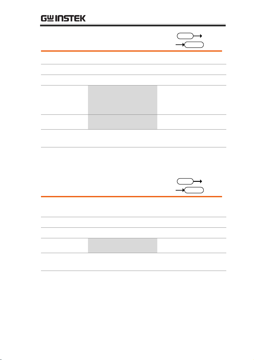
Air inlet LCD Display Power key
FUNC/File
Help/Utility
Short
Load On/Off
USB Port, Preset
and Shift keys
Number pad, Clear/
Lock and Enter keys
Main/Local
Scroll wheel
Function keys
Input
terminals
I MON OUT,
TRIG OUT
Front Panel Overview
(PEL-3021/PEL-3041 shown)
3

PEL-3000 Programming Manual
47 - 63 Hz
90 VA MAX.
AC
100 - 120 VAC
200 - 240 VAC
FRAME CONT
J 1
J 2
SER. NO. LB
RS232C
GPIB
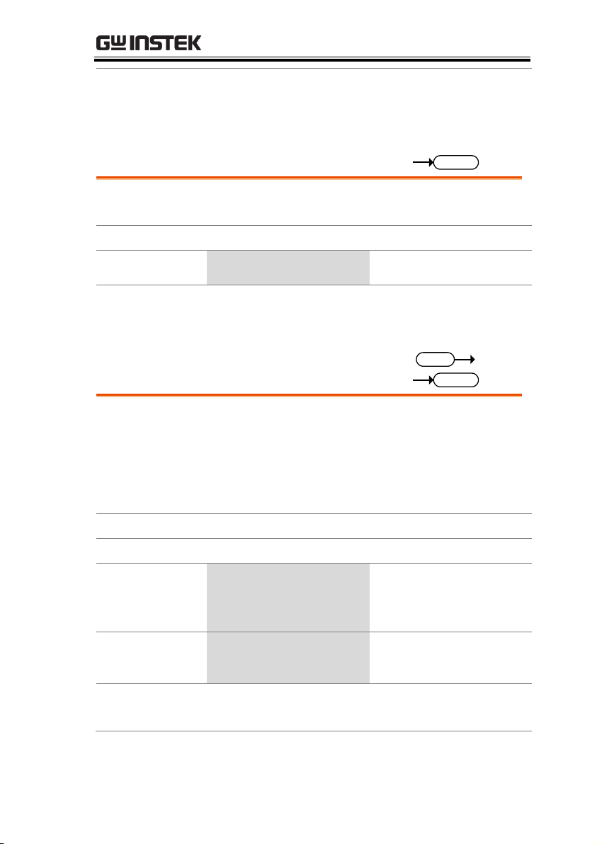
WARNING
TO AVOID ELECTRIC SHOCK THE POWER CORD
DO NOT REMOVE COVERS.
NO OPERATOR SERVICEABLE COMPONENTS INSIDE.
PROTECTIVE GROUNDING CONDUCTOR MUST BE
REFER SERVICING TO QUALIFIED PERSONNEL.
CONNECTED TO GROUND.
Remote sense
inputs
Frame control ports,
J1, J2
RS232C port
USB port
USB device port
Exhaust fanGPIB Power socket
Rear panel
inputs
Rear Panel Overview
(PEL-3021 / PEL-3041 shown)
4

INTERFACE OVERVIEW
USB
configuration
PC side
connector
Type A, host
PEL-3000 side
connector
Rear panel Type B, slave
Speed
2.0 (full speed)
USB Class
USB CDC AMC
Note
Before USB can be used for remote control, it is
necessary to install the PEL-3000 USB device
driver, located on the accompanying User Manual
CD.
Operation
1. Connect the USB cable to the rear panel USB B
port.
2. Press
Shift
+
Utility
Help
> Interface[F3] and set
the Interface setting to USB.
Interface Configuration
Configure to USB Remote Interface
5

PEL-3000 Programming Manual
Operation
1. Ensure the PEL-3000 is off before proceeding.
2. Connect a GPIB cable from a GPIB controller to
the GPIB port on the PEL-3000.
3. Turn the PEL-3000 on.
4. Press
Shift
+
Utility
Help
> Interface[F3] and set
the Interface setting to GPIB.
5. Set the GPIB address.
GPIB address
0~30
GPIB constraints
Maximum 15 devices altogether, 20m cable length,
2m between each device
Unique address assigned to each device
At least 2/3 of the devices turned On
No loop or parallel connection
Pin Assignment
112
1324
Pin
Signal
Pin
Signal 1~4
Data I/O 1~4
13~16
Data I/O 5~8
5 EOI
17
REN 6
DAV
18
Ground (DAV)
7 NRFD
19
Ground (NRFD)
8 NDAC
20
Ground (NDAC)
9 IFC
21
Ground (IFC)
10
SRQ
22
Ground (SRQ)
Configure GPIB Interface
To use GPIB, the optional GPIB port must be installed. See the user
manual for details.
6

INTERFACE OVERVIEW
11
ATN
23
Ground (ATN)
12
SHIELD Ground
24
Single GND
RS232C
Configuration
Connector
DB-9, Male
Baud Rate
2400, 4800, 9600, 19200, 38400
Stop Bit
1, 2
Parity
None, Odd, Even
Operation
1. Connect an RS232C cable from the PC to the
rear panel RS232 port.
2. Press
Shift
+
Utility
Help
> Interface[F3] and
set the Interface setting to RS232.
3. Set the Baud Rate, Stop Bit and Parity settings.
Pin Assignment
1 2 3 4 5
6 7 8 9
2: RxD (Receive data)
3: TxD (Transmit data)
5: GND
4, 6 ~ 9: No connection
PC Connection
Use a null modem connection as shown in the
diagram below.
PEL-3000 PC
RxDPin2 RxD Pin2
GNDPin5 GND Pin5
TxD Pin3
TxDPin3
Configure RS232C
7

PEL-3000 Programming Manual
Functionality
check
Invoke a terminal application such as
RealTerm. For RS232C, set the COM port, baud
rate, stop bit, data bit and parity accordingly.
To check the COM settings, see the Device
Manager in the PC. For WinXP; Control panel
→ System → Hardware tab.
Run this query command via the terminal after
the instrument has been configured for
RS232/USB remote control (page 5).
*idn?
This should return the Manufacturer, Model
number, Serial number, and Firmware version
in the following format.
GW-INSTEK,PEL-3000, XXXXXXXXXXXX,
V.X.X.X.X
Manufacturer: GW-INSTEK
Model number : PEL-3000
Serial number : XXXXXXXXXXXX
Firmware version : V.X.X.X
RS232C/USB Remote Control Function Check
8

INTERFACE OVERVIEW
Background
Realterm is a terminal program that can used to
communicate with a device attached to the
serial port of a PC or via an emulated serial port
via USB.
The following instructions apply to version
1.99.0.27. Even though Realterm is used as an
example to establish a remote connection, any
terminal program can be used that has similar
functionality.
Note
Realterm can be downloaded on Sourceforge.net
free of charge.
For more information please see
http://realterm.sourceforge.net/
Operation
1. Download Realterm and install according to the
instructions on the Realterm website.
2. Connect the PEL-3000 via USB (page 5) or via
RS232 (page 7).
3. If using RS232, make note of the configured
baud rate, stop bits and parity.
4. Go to the Windows device manager and find
the COM port number for the connection.
For example, go to the Start menu > Control
Panel > Device Manager
Double click the Ports icon to reveal the
connected serial port devices and the COM port
for the each connected device.
Using Realterm to Establish a Remote Connection
9

PEL-3000 Programming Manual
If using USB, the baud rate, stop bit and parity
settings can be viewed by right-clicking the
connected device and selecting the Properties
option.
5. Start Realterm on the PC as an administrator.
Click:
Start menu>All Programs>RealTerm>realterm
Tip: to run as an administrator, you can right
click the Realterm icon in the Windows Start
menu and select the Run as Administrator
option.
10

INTERFACE OVERVIEW
6. After Realterm has started, click on the Port tab.
Enter the Baud, Parity, Data bits, Stop bits and
Port number configuration for the connection.
The Hardware Flow Control, Software Flow
Control options can be left at the default
settings.
Press Open to connect to the PEL-3000.
11

PEL-3000 Programming Manual
7. Click on the Send tab.
In the EOL configuration, check on the +CR and
+LF check boxes.
Enter the query:
*idn?
Click on Send ASCII.
8. The terminal display will return the following:
GW, PEL-3XXX,EXXXXXXX,VX.XX.XXX
(manufacturer, model, serial number, version)
9. If Realterm fails to connect to the PEL-3000,
please check all the cables and settings and try
again.
12

INTERFACE OVERVIEW
Functionality
check
Please use the National Instruments
Measurement & Automation Controller
software to confirm GPIB/LAN functionality.
See the National Instrument website,
http://www.ni.com for details.
Operation
1. Start the NI Measurement and
Automation Explorer (MAX)
program. Using Windows, press:
Start>All Programs>National
Instruments>Measurement & Automation
2. From the Configuration panel access;
My System>Devices and Interfaces>GPIB0
GPIB Function Check
13

PEL-3000 Programming Manual
3. Press the Scan for Instruments button.
4. In the Connected Instruments panel the PEL-3000
should be detected as Instrument 0 with the
address the same as that configured on the
PEL-3000.
5. Double click the Instrument 0 icon.
2
3
4
5
6. Click on Communicate with Instrument.
7. In the NI-488.2 Communicator window, ensure
*IND? is written in the Send String: text box.
Click on the Query button to send the *IDN?
query to the instrument.
8. The String Received text box will display the
query return:
GW, PEL-3XXX,EXXXXXXX,VX.XX.XXX
(manufacturer, model, serial number, version)
14

INTERFACE OVERVIEW
6
7
8
9. The function check is complete.
15

PEL-3000 Programming Manual
Compatible
Standard
IEEE488.2
Partial compatibility
SCPI, 1999
Partial compatibility
Command
Structure
SCPI (Standard Commands for Programmable
Instruments) commands follow a tree-like
structure, organized into nodes. Each level of
the command tree is a node. Each keyword in a
SCPI command represents each node in the
command tree. Each keyword (node) of a SCPI
command is separated by a colon (:).
For example, the diagram below shows an SCPI
sub-structure and a command example.
:RESPonse:CRANGe :VRANGe
[:MODE]:CRANGe
:MODE
COMMNAND OVERVIEW
The Command overview chapter lists all PEL-3000 commands in
functional order as well as alphabetical order. The command syntax
section shows you the basic syntax rules you have to apply when
using commands.
Command Syntax
16

COMMNAND OVERVIEW
Command types
There are a number of different instrument
commands and queries. A command sends
instructions or data to the unit and a query
receives data or status information from the
unit.
Command types
Simple
A single command
with/without a parameter
Example
:CONFigure:RESPonse MAX
Query
A query is a simple or
compound command
followed by a question mark
(?). A parameter (data) is
returned.
Example
:CONFigure:RESPonse?
Compound
Two or more commands on
the same command line.
Compound commands are
separated with either a semicolon (;) or a semi-colon and a
colon (;:).
A semi-colon is used to join
two related commands, with
the caveat that the last
command must begin at the
last node of the first
command.
A semi-colon and colon are
used to combine two
commands from different
17

PEL-3000 Programming Manual
nodes.
Example
CONFigure:VON
MAX;:CONFigure:VDELay
MIN
Command Forms
Commands and queries have two different
forms, long and short. The command syntax is
written with the short form of the command in
capitals and the remainder (long form) in lower
case.
The commands can be written in capitals or
lower-case, just so long as the short or long
forms are complete. An incomplete command
will not be recognized.
Below are examples of correctly written
commands.
Long
form
:CURRent:LEVel?
:CURRENT:LEVEL?
:current:level?
Short
form
:CURR:LEV?
:curr:lev?
Square Brackets
Commands that contain square brackets
indicate that the contents are optional. The
function of the command is the same with or
without the square bracketed items, as shown
below
For example for the query:
“[:CONFigure]:GNG [:PASS]?”
Both “:CONFigure:GNG:PASS?” and “:GNG?”
are both valid forms.
18

Command
Format
1.0 0A
1
2 3 4
:CURRent:Set
1. Command header
2. Space
3. Parameter 1
4. Unit or suffix.
Common
Input Parameters
Type
Description
Example
<Boolean>
boolean logic
0, 1
<NR1>
integers
0, 1, 2, 3
<NR2>
decimal
numbers
0.1, 3.14, 8.5
<NR3>
floating point
4.5e-1, 8.25e+1
<NRf>
any of NR1, 2, 3
1, 1.5, 4.5e-1
[MIN]
(Optional
parameter)
For commands, this will set the
setting to the lowest value. This
parameter can be used in place of
any numerical parameter where
indicated.
For queries, it will return the
lowest possible value allowed for
the particular setting.
[MAX]
(Optional
parameter)
For commands, this will set the
setting to the highest value. This
parameter can be used in place of
any numerical parameter where
indicated.
For queries, it will return the
highest possible value allowed
for the particular setting.
Unit Suffixes
(Optional
parameters)
Unit suffixes can be optionally
used with most NRf type input
parameters.
COMMNAND OVERVIEW
19

PEL-3000 Programming Manual
[A]
Amps
1.00A
[%]
Percentage
10%
[V]
Volts
5.00V
[W]
Watts
3.00W
[mS]
milliseconds
20mS
[mV]
Millivolts
150mV
[S]
Seconds
5S
[MHO]
Reciprocal of
one ohm
0. 02MHO
[mA/uS]
Millamps/
microsecond
100mA/uS
[Hz]
Hertz
1000Hz
Message
Terminator
LF
Line feed code (0x0A)
20

COMMNAND OVERVIEW
Common
Commands
*CLS ....................................................................................... 25
*ESE ....................................................................................... 25
*ESR? ..................................................................................... 26
*IDN? ..................................................................................... 26
*OPC ...................................................................................... 27
*RCL ....................................................................................... 27
*RST ....................................................................................... 27
*SAV ....................................................................................... 28
*SRE ....................................................................................... 28
*STB? ..................................................................................... 29
*TRG ...................................................................................... 29
*TST? ..................................................................................... 30
Trigger
Commands
:ABORt .................................................................................. 30
:INPut ..................................................................................... 30
:INPut:SHORt ...................................................................... 31
Measurement
Commands
:MEASure:CURRent? .......................................................... 32
:MEASure:VOLTage? .......................................................... 32
:MEASure:POWer? .............................................................. 32
:MEASure:ETIMe? ............................................................... 33
Configure
Subsystem
Commands
[:CONFigure]:OCP .............................................................. 34
[:CONFigure]:OPP ............................................................... 35
[:CONFigure]:UVP ............................................................... 36
[:CONFigure]:OVP .............................................................. 36
[:CONFigure]:SSTart ............................................................ 37
[:CONFigure]:VON ............................................................. 38
[:CONFigure]:VDELay ........................................................ 38
:CONFigure:RESPonse ....................................................... 39
[:CONFigure]:CNTime ........................................................ 40
[:CONFigure]:COTime ........................................................ 40
[:CONFigure]:CRUnit .......................................................... 41
:CONFigure:DYNamic ........................................................ 41
:CONFigure:MEMory .......................................................... 42
:CONFigure:SHORt ............................................................. 43
Command List
21

PEL-3000 Programming Manual
[:CONFigure]:GNG:SPECtest ........................................... 43
[:CONFigure]:GNG:DTIMe .............................................. 44
[:CONFigure]:GNG:MODE .............................................. 44
[:CONFigure]:GNG[:PASS]................................................ 45
[:CONFigure]:GNG:H ........................................................ 45
[:CONFigure]:GNG:L ......................................................... 46
[:CONFigure]:GNG:C ......................................................... 46
Parallel
Commands
[:CONFigure]:PARallel ........................................................ 47
Step Commands
[:CONFigure]:STEP:CCH ................................................... 48
[:CONFigure]:STEP:CCM .................................................. 49
[:CONFigure]:STEP:CCL .................................................... 50
[:CONFigure]:STEP:CC ...................................................... 50
[:CONFigure]:STEP:CRH ................................................... 51
[:CONFigure]:STEP:CRM .................................................. 51
[:CONFigure]:STEP:CRL .................................................... 52
[:CONFigure]:STEP:CR ...................................................... 52
[:CONFigure]:STEP:CVH ................................................... 53
[:CONFigure]:STEP:CVL ................................................... 53
[:CONFigure]:STEP:CV ...................................................... 54
[:CONFigure]:STEP:CPH ................................................... 54
[:CONFigure]:STEP:CPM ................................................... 55
[:CONFigure]:STEP:CPL .................................................... 55
[:CONFigure]:STEP:CP ...................................................... 56
External
Commands
[:CONFigure]:EXTernal[:CONTrol] ................................. 57
[:CONFigure]:EXTernal:LOADonin ................................ 57
[:CONFigure]:EXTernal:SYNC ......................................... 58
Mode Subsystem
Commands
:MODE .................................................................................. 59
[:MODE]:CRANge .............................................................. 59
[:MODE]:VRANge .............................................................. 60
[:MODE]:RESPonse ............................................................ 60
[:MODE]:DYNamic ............................................................ 61
22

COMMNAND OVERVIEW
Current
Subsystem
Commands
:CURRent[:VA] ..................................................................... 62
:CURRent:VB ........................................................................ 63
:CURRent:SRATe ................................................................. 63
:CURRent:L1 ......................................................................... 64
:CURRent:L2 ......................................................................... 64
:CURRent:SET ...................................................................... 65
:CURRent:LEVel .................................................................. 66
:CURRent:RISE .................................................................... 66
:CURRent:FALL ................................................................... 67
:CURRent:T1 ......................................................................... 67
:CURRent:T2 ......................................................................... 68
:CURRent:FREquency ......................................................... 69
:CURRent:DUTY ................................................................. 69
Resistance
Subsystem
Commands
:RESistance[:VA] .................................................................. 71
:RESistance:VB ..................................................................... 72
:RESistance:SRATe .............................................................. 72
:RESistance:L1 ...................................................................... 73
:RESistance:L2 ...................................................................... 74
:RESistance:SET ................................................................... 74
:RESistance:LEVel................................................................ 75
:RESistance:RISE ................................................................. 76
:RESistance:FALL ................................................................ 76
:RESistance:T1 ...................................................................... 77
:RESistance:T2 ...................................................................... 78
:RESistance:FREquency ...................................................... 78
:RESistance:DUTY ............................................................... 79
Voltage
Subsystem
Commands
:VOLTage[:VA] ..................................................................... 81
:VOLTage:VB ....................................................................... 81
Power Subsystem
Commands
:POWer[:VA] ......................................................................... 83
:POWer:VB ............................................................................ 84
:POWer:L1 ............................................................................. 84
:POWer:L2 ............................................................................. 85
:POWer:SET ......................................................................... 85
:POWer:LEVel ...................................................................... 86
:POWer:T1 ............................................................................ 87
:POWer:T2 ............................................................................ 87
23

PEL-3000 Programming Manual
:POWer:FREquency ............................................................. 88
:POWer:DUTY ..................................................................... 89
24

COMMNAND OVERVIEW
*CLS ....................................................................................... 25
*ESE ....................................................................................... 25
*ESR? ..................................................................................... 26
*IDN? ..................................................................................... 26
*OPC ...................................................................................... 27
*RCL ....................................................................................... 27
*RST ....................................................................................... 27
*SAV ....................................................................................... 28
*SRE ....................................................................................... 28
*STB? ..................................................................................... 29
*TRG ...................................................................................... 29
*TST? ..................................................................................... 30
*CLS
Set
Description
Clears the error queue.
Query Syntax
*CLS
*ESE
Set
Query
Description
Queries or sets the Standard Event Status Enable
register. The Standard Event Status Enable register
determines which events can set the Event
Summary bit (ESB) in the Status Byte Register. Any
bits that are set to 1 enable the corresponding
event. Each event is represented by a bit in the
Standard Event Status Enable register.
Syntax
*ESE <NR1>
Query Syntax
*ESE?
Parameter/
Return parameter
<NR1> (bit weight)
Bit number / Description
4
3/ QYE
8 4/ DDE
16
5/ EXE
32
6/ CME
Common Commands
25

PEL-3000 Programming Manual
Example
*ESE 8
Sets bit 4 of the ESE register.
Query example
*ESE?
>12
Bits 3 and 4 are set in the Standard Event Status
Enable register.
*ESR?
Set
Query
Description
Reads the Standard Event Status register. This
command will also clear the Standard Event Status
register.
Query Syntax
*ESR?
Return parameter
<NR1> (bit weight)
Bit number / Description
4
3/ QYE
8 4/ DDE
16
5/ EXE
32
6/ CME
Query example
*ESR?
>48
Bits 5 and 6 are set in the Standard Event register.
*IDN?
Query
Description
Queries the manufacturer, model number, serial
number, and firmware version of the instrument.
Query Syntax
*IDN?
Return parameter
<string>
Returns the instrument identification as a
string in the following format:
GW-INSTEK, PEL-3021, XXXXXXXX, V.VV
Manufacturer: GWINSTEK
Model number : PEL-3021
Serial number : XXXXXXXX
Firmware version : V.VV
26

COMMNAND OVERVIEW
*OPC
Set
Query
Description
This command sets the OPC (Operation Command
Bit) bit (bit 0) of the Standard Event Status Register
after the instrument has completed all pending
operations. The query will return the status of the
OPC bit.
Syntax
*OPC
Query Syntax
*OPC?
Return parameter
<NR1>
1
Operation complete
Query Example
*OPC?
>1
Indicates that all pending operations are complete.
*RCL
Set
Description
The Recall Instrument State command restores the
instrument settings from a previously saved
memory setting.
Syntax
*RCL <NR1>
Parameter
<NR1>
1~256
Memory number 1 to 256
Example
*RCL 20
Recall setting memory 20.
*RST
Set
Description
Resets the unit. This is command forces the
ABORt, and *CLS
Query Syntax
*RST
27

PEL-3000 Programming Manual
*SAV
Set
Description
The Save Instrument State command saves the
instrument settings to one of the memory setting
slots.
Syntax
*SAV <NR1>
Parameter
<NR1>
1~256
Memory number 1 to 256
Example
*SAV 20
Saves the current setting to memory 20.
*SRE
Set
Query
Description
Queries or sets the Service Request Enable register.
The Service Request Enable register determines
which events in the Status Byte register can set the
Master Summary bit (MSB) in the Status Byte
Register. Any bits that are set to 1 will cause the
MSS bit to be set.
Syntax
*SRE <NR1>
Query Syntax
*SRE?
Parameter/
Return parameter
<NR1> (bit weight)
Bit number / Description
1
1/Not used
2
2/ERR
4
3/ CSUM
8 4/ QUES
16
5/ MAV
32
6/ ESB
64
7/ RQS_MSS
128
8/ OPER
Note: Bit 1 and 2 cannot be set, however bit 2 (ERR)
can be returned.
Example
*SRE 8
Sets bit 4 of the Service Request Enable register.
28

COMMNAND OVERVIEW
Query example
*SRE?
>12
Bits 3 and 4 are set in the Service Request Enable
register.
*STB?
Set
Query
Description
Reads the Status Byte register. This command will
not clear the Status Byte register.
If the Master Summary Status bit (MSS) is set, it
indicates that there is a reason for a service
request.
Query Syntax
*STB?
Return parameter
<NR1> (bit weight)
Bit number / Description
1
1/Not used
2 2/ERR
4 3/ CSUM
8 4/ QUES
16
5/ MAV
32
6/ ESB
64
7/ RQS_MSS
128
8/ OPER
Note: Bit 1 and 2 cannot be set, however bit 2 (ERR)
can be returned.
Query example
*STB?
>36
Bits 3 and 6 are set in the Status Byte register.
*TRG
Set
Description
This command triggers the unit.
Query Syntax
*TRG
29

PEL-3000 Programming Manual
*TST?
Set
Query
Description
This command is a standard SCPI self-test
command. The PEL-3000 does not perform any
self-tests so will always return 0 (pass) for this
command.
Query Syntax
*TST?
Return parameter
<NR1>
0 Pass
Query example
*TST?
>0
*WAI
Set
Description
Wait command. Prevents new operations from
executing until all pending operations have
finished.
Query Syntax
*TRG
:ABORt ..................................................................................................................... 30
:INPut ........................................................................................................................ 30
:INPut:SHORt ......................................................................................................... 31
:ABORt
Set
Description
Turns the load off. (and the loads of all connected
slave devices.)
Query Syntax
:ABORt
:INPut
Set
Query
Description
Sets or queries the status of the load.
Trigger Commands
30

COMMNAND OVERVIEW
Syntax
:INPut {<Boolean>|OFF | ON}
Query Syntax
:INPut?
Parameter
parameter
OFF or 0
Load = OFF
ON or 1
Load = ON
Return parameter
0
Load = OFF
1
Load = ON
Example
:INPut ON
Turns the load on.
Query example
:INPut?
>0
Indicates that the load is off.
:INPut:SHORt
Set
Query
Description
Shorts or opens the input terminals or queries their
status.
Syntax
:INPut:SHORt {<Boolean>|OFF | ON}
Query Syntax
:INPutSHORt?
Parameter
parameter
OFF or 0
Short = OFF
ON or 1
Short = ON
Return parameter
0
Short = OFF
1
Short = ON
Example
:INPut:SHORt ON
Shorts the input terminals.
Query example
:INPut:SHORt?
>0
Indicates that the terminals are open.
31

PEL-3000 Programming Manual
:MEASure:CURRent? ............................................................................................. 32
:MEASure:VOLTage? ............................................................................................. 32
:MEASure:POWer? ................................................................................................. 32
:MEASure:ETIMe? .................................................................................................. 33
:MEASure:CURRent?
Set
Query
Description
This command returns the load current.
Query Syntax
:MEASure:CURRent?
Return parameter
<NR2>
Load current in amps
Query example
:MEASure:CURRent?
>0.79860
Returns the load current in amps.
:MEASure:VOLTage?
Set
Query
Description
This command returns the load voltage.
Query Syntax
:MEASure:VOLTage?
Return parameter
<NR2>
Load voltage in volts
Query example
:MEASure:VOLTage?
>1.49900
Returns the load voltage in volts.
:MEASure:POWer?
Set
Query
Description
This command returns the power.
Query Syntax
:MEASure:POWer?
Return parameter
<NR2>
Power in watts
Query example
:MEASure:POWer?
>1.19695
Returns the power in watts.
Measurement Commands
32

COMMNAND OVERVIEW
:MEASure:ETIMe?
Set
Query
Description
Returns the amount of time the load has been on
for in seconds (elapsed time).
Query Syntax
:MEASure:ETIME?
Return parameter
<NR2>
Elapsed time in seconds
Query example
:MEASure:ETIME?
>316.0
Returns the elapsed time in seconds.
33

PEL-3000 Programming Manual
[:CONFigure]:OCP .............................................................. 34
[:CONFigure]:OPP ............................................................... 35
[:CONFigure]:UVP .............................................................. 36
[:CONFigure]:OVP .............................................................. 36
[:CONFigure]:SSTart............................................................ 37
[:CONFigure]:VON ............................................................. 38
[:CONFigure]:VDELay ....................................................... 38
:CONFigure:RESPonse ....................................................... 39
[:CONFigure]:CNTime ........................................................ 40
[:CONFigure]:COTime ........................................................ 40
[:CONFigure]:CRUnit .......................................................... 41
:CONFigure:DYNamic ........................................................ 41
:CONFigure:MEMory .......................................................... 42
:CONFigure:SHORt ............................................................ 43
[:CONFigure]:GNG:SPECtest ........................................... 43
[:CONFigure]:GNG:DTIMe .............................................. 44
[:CONFigure]:GNG:MODE .............................................. 44
[:CONFigure]:GNG[:PASS] ............................................... 45
[:CONFigure]:GNG:H ........................................................ 45
[:CONFigure]:GNG:L ......................................................... 46
[:CONFigure]:GNG:C ......................................................... 46
[:CONFigure]:OCP
Set
Query
Description
Sets or queries the OCP trip settings. The OCP
limit can be set to a specific value or the trip setting
can be set to either limit the current or to turn the
load off.
Syntax
[:CONFigure]:OCP {<NR2>[ A ] | MINimum |
MAXimum | LIMit | LOFF }
Query Syntax
[:CONFigure]:OCP?
Parameter
<NR2>[A]
Current limit value.
Configure Subsystem Commands
34

COMMNAND OVERVIEW
MINIMUM or MIN
MAXIMUM or MAX
LIMIT or LIM
Minimum current limit
value.
MAXimum current limit
value.
Limit the load
LOFF
Turn the load off
Return parameter
Returns a string with OPC setting followed by the OPC
value.
Example1
:OPC LIM
Sets the OCP setting to limit.
Example2
:OPC 77.000
Sets the OCP value to 77A.
Query example
:OPC?
>LIMIT, 77.000
The OCP setting is LIMIT and the OPC value is
77.000A.
[:CONFigure]:OPP
Set
Query
Description
Sets or queries the OPP trip settings. The OPP limit
can be set to a specific value or the trip setting can
be set to either limit the power or to turn the load
off.
Syntax
[:CONFigure]:OPP {<NR2>[ W] | MINimum |
MAXimum | LIMit | LOFF }
Query Syntax
[:CONFigure]:OPP?
Parameter
<NR2>[W]
Power limit value.
MINIMUM or MIN
MAXIMUM or MAX
LIMIT or LIM
MINIMUM power limit
value.
MAXIMUM power limit
value.
Limit the load
LOFF
Turn the load off
Return parameter
Returns a string with OPP setting followed by the OPP
value.
35

PEL-3000 Programming Manual
Example1
:OPP LIMIT
Sets the OCP setting to limit.
Example2
:OPP 10.000
Sets the OPP value to 10W.
Query example
:OPP?
>LIMIT, 10.000
The OPP setting is LIMIT and the OPP value is
10.000W.
[:CONFigure]:UVP
Set
Query
Description
Sets or queries the UVP trip settings. The UVP can
also be cleared with this command.
Syntax
[:CONFigure]:UVP {<NR2>[ V ] |MINimum |
MAXimum}
Query Syntax
[:CONFigure]:UVP?
Parameter
<NR2>[V]
voltage limit value.
MINIMUM or MIN
MINIMUM value.
MAXIMUM or MAX
MAXIMUM value.
Return parameter
Returns the UVP level (<NR2>)
Example1
:UVP 10.00
Sets the UVP setting to 10V.
Query example
:UVP?
> 10.0000
The UVP setting is 10.0000V.
[:CONFigure]:OVP
Set
Query
Description
Sets or queries the OVP trip settings. The OVP can
also be cleared with this command.
Syntax
[:CONFigure]:OVP {<NR2>[ V ] | MINimum|
MAXimum}
36

COMMNAND OVERVIEW
Query Syntax
[:CONFigure]:OVP?
Parameter
<NR2>[V]
voltage limit value.
MINIMUM or MIN
MINIMUM value.
MAXIMUM or MAX
MAXIMUM value.
Return parameter
Returns the OVP level (<NR2>).
Example1
:OVP 10.00
Sets the OVP setting to 10V.
Query example
:OVP?
> 10.0000
The OVP setting is 10.0000V.
[:CONFigure]:SSTart
Set
Query
Description
Sets or queries the Soft Start time setting.
Syntax
[:CONFigure]:SSTart {<NR2>[ S] | MINimum|
MAXimum | OFF}
Query Syntax
[:CONFigure]:SSTart?
Parameter
<NR2>[S]
The soft start time in
seconds.
MINIMUM or MIN
Minimum time = 0 second
MAXIMUM or MAX
Maximum time
OFF
OFF = 0 second
Return parameter
<NR2>
Returns the soft start time
in seconds.
OFF
Off
Example
:SSTart OFF
Turns the soft start function off.
Query example
:SSTart?
>OFF
The soft start function is off.
37

PEL-3000 Programming Manual
[:CONFigure]:VON
Set
Query
Description
Sets or queries the Von voltage settings.
Syntax
[:CONFigure]:VON {<NR2>[ V ] | MINimum|
MAXimum | LON | LOFF }
Query Syntax
[:CONFigure]:VON?
Parameter
{<NR2>[ V ]
The Von voltage level
(default unit is V)
MINIMUM or MIN
Minimum Von voltage
level
MAXIMUM or MAX
Maximum Von voltage
level
LON
Latch on
LOFF
Latch off
Return parameter
<ASCII string>
Returns the Von latch
settings.
Example
:VON 10.0V
Sets the Von voltage to 10.0 volts.
Query example
:VON?
>Latch OFF, 10.000
The Von voltage level is 10V.
[:CONFigure]:VDELay
Set
Query
Description
Sets or queries the Von Delay settings in seconds.
Syntax
[:CONFigure]:VDELay <NR2>[S] | MINimum |
MAXimum | OFF
Query Syntax
[:CONFigure]:VDELay?
Parameter
<NR2>[ S]
The delay time in seconds
OFF
Disable the delay time
MINIMUM or MIN
Minimum delay time
MAXIMUM or MAX
Maximum delay time
Return parameter
<NR2>
Returns the delay time in
seconds
38

COMMNAND OVERVIEW
Example
:VDELay 1.5 mS
Sets the delay time to 1.5mS.
:VDELay 0.0015 S
Sets the delay time to 1.5mS.
Query example
:VDELay?
>0.0015
The delay time is 1.5mS.
:CONFigure:RESPonse
Set
Query
Description
Sets or queries the response speed. This is the
equivalent to the CV Mode Response Speed or
CC and CR Mode Response Speed settings on the
front panel.
Syntax
:CONFigure:RESPonse {<NR2>0.1| 0.2 | 0.5 | 1.0|
MINimum | MAXimum |FAST | SLOW}
Query Syntax
:CONFigure:RESPonse?
Parameter
<NR2>
0.1, 0.2, 0.5, 1.0 (for CC
or CR mode only)
MINIMUM or MIN
Minimum response
speed
MAXIMUM or MAX
Maximum response
speed
FAST
Fast response speed
(CV mode only)
SLOW
Slow response speed
(CV mode only)
Return parameter
<ASCII string>
Returns the response
settings for all the
applicable modes as a
string
Example
:CONFigure:RESPonse MAX
Sets the response to the maximum.
39

PEL-3000 Programming Manual
Query example
:CONFigure:RESPonse?
>CV mode response:FAST, CC and CR mode their
response:1/1
Returns the response as CV=fast and CC, CR= 1/1.
[:CONFigure]:CNTime
Set
Query
Description
Turns the Count Time timer function on or off.
Syntax
[:CONFigure]:CNTime {<Boolean> |OFF | ON}
Query Syntax
[:CONFigure]:CNTime?
Parameter/
Return parameter
OFF or 0
Turns the Count Time
timer off.
ON or 1
Turns the Count Time
timer on
Example
[:CONFigure]:CNTime ON
Turns the Count Time timer on.
Query example
[:CONFigure]:CNTime?
>ON
Count Time is turned on.
[:CONFigure]:COTime
Set
Query
Description
Sets or queries the load cutoff time. A cutoff time
of 0 seconds is the equivalent of disabling the
cutoff time.
Syntax
[:CONFigure]:COTime {<NR2>[S] | MINimum |
MAXimum | OFF }
Query Syntax
[:CONFigure]:COTime?
Parameter
<NR2>[S]
Cut off time in seconds
(1~3599999)
OFF
Turns the cutoff time off.
MINIMUM or MIN
Sets the cutoff time to the
maximum
MAXIMUM or MAX
Sets the cutoff time to the
minimum
40

COMMNAND OVERVIEW
Return parameter
<NR2>
Returns the cutoff time
Example
:COTime MAX
Sets the cutoff time to the maximum.
Query example
:COTime?
>3599999
The cutoff time is set to3599999 seconds.
[:CONFigure]:CRUnit
Set
Query
Description
Sets or queries the CR mode setting units.
Syntax
[:CONFigure]:CRUnit {OHM|MHO|?}
Query Syntax
[:CONFigure]:CRUnit?
Parameter/
Return parameter
OHM
Set the units to ohms.
MHO
Set the units to mho
(conductance)
Example
:CRUnit OHM
Sets the CR mode units to ohms.
Query example
:CRUnit?
>OHM
The CR mode units are ohms.
:CONFigure:DYNamic
Set
Query
Description
Sets the display units for when dynamic mode
switching is used. Units can be selected from
Percent and Value. See the user manual for further
details. This command will also configure whether
to switch between each level using timers or a set
duty cycle.
Syntax
:CONFigure:DYNamic { VALue | PERCent | TIME |
FDUTy }
Query Syntax
:CONFigure:DYNamic?
Parameter
VALUE or VAL
Set the units to Value.
PERCENT or PERC
Set the units to Percent.
41

PEL-3000 Programming Manual
TIME
Use timers for timing.
FDUTY or FUDT
Use duty cycle for timing.
Return parameter
<ASCII string>
Return a string containing
the unit mode and the
timing mode.
Example
:CONFigure:DYNamic VALue
Sets the dynamic mode units to value.
Query example
:CONFigue:DYNamic?
> Dynamic, ;Dynamic Level:Value, Dynamic
Time:T1/T2
:CONFigure:MEMory
Set
Query
Description
This command configures the how the files are
recalled in local mode (using the front panel
interface). By default when you try to recall a file
or setting from memory, a message will appear
asking you to press the Enter key to confirm each
time you wish to recall. This command enables
(SAFEty) or disables this feature (DIRect).
Syntax
:CONFigure:MEMory {SAFety | DIRect}
Query Syntax
:CONFigure:MEMory?
Parameter
SAFETY or SAF
Safety setting.
DIRECT or DIR
Directly recall the chosen
file.
Return parameter
Safety
Safety setting.
Direct
Directly setting.
Example
:CONFigure:MEMory SAFEty
Enables the safety setting.
Query example
:CONFigure:MEMory?
>Safety
The safety setting is enabled.
42
COMMNAND OVERVIEW
:CONFigure:SHORt
Set
Query
Description
Configures the short key.
Syntax
:CONFigure:SHORt { TOGGle | HOLD}
Query Syntax
:CONFigure:SHORt?
Parameter
HOLD
Sets the button
configuration to hold
TOGGLE or TOGG
Sets the button
configuration to toggle
Return parameter
Toggle
Toggle
Hold
Hold
Example
:CONFigure:SHORt TOGGle
Sets the Short key configuration to toggle.
Query example
:CONFigure:SHORt?
>Toggle
The Short key is configured to toggle.
[:CONFigure]:GNG:SPECtest
Set
Query
Description
Enables/Disables Go-NoGo testing (SPEC test =
ON/SPEC test = OFF).
Syntax
[:CONFigure]:GNG:SPECtest {<Boolean>|OFF | ON}
Query Syntax
[:CONFigure]:GNG:SPECtest?
Parameter/
Return parameter
OFF or 0
SPEC test = OFF
ON or 1
SPEC test = ON
Example
:GNG:SPECtest ON
Turns Go-NoGo testing on.
Query example
:GNG:SPECtest?
>OFF
Indicates that Go-NoGo testing is off.
43

PEL-3000 Programming Manual
[:CONFigure]:GNG:DTIMe
Set
Query
Description
Sets or queries the Go-NoGo delay time.
Syntax
[:CONFigure]:GNG:DTIMe {<NR2>[ S ] | MINimum
|MAXimum}
Query Syntax
[:CONFigure]:GNG:DTIMe?
Parameter
<NR2>[S]
Sets the Go-NoGo delay
time in seconds (0.0~1.0)
with 0.1 second resolution.
MINIMUM or MIN
Minimum delay time
MAXimum or MAX
Maximum delay time
Return parameter
<NR2>
Returns the delay time in
seconds.
Example
:GNG:DTIMe 0.5
Sets the delay time to 0.5 seconds.
Query example
:GNG:DTIMe?
>0.5
The delay time is 0.5 seconds.
[:CONFigure]:GNG:MODE
Set
Query
Description
Sets or queries the entry mode for the Go-NoGo
settings. The entry mode determines whether the
Go-NoGo limits are set as values or as a
percentage value from a center reference value.
Syntax
[:CONFigure]:GNG:MODE {PERCent | VALue}
Query Syntax
[:CONFigure]:GNG:MODE?
Parameter
PERCENT or PERC
Sets the entry mode to %.
VALUE or VAL
Sets the entry mode to
value
Return parameter
Percent
% entry mode
Value
Value entry mode
Example
:GNG:MODE PERCENT
Sets the entry mode to %.
44
COMMNAND OVERVIEW
Query example
:GNG:MODE?
>Percent
The entry mode is %.
[:CONFigure]:GNG[:PASS]
Set
Query
Description
Queries the Go-NoGo test result(s). This command
can be used for all test modes (CC, CV, CR, CP).
Query Syntax
[:CONFigure]:GNG[:PASS]?
Return parameter
NG
No Go (fail)
GO
Go (Pass)
Query example
:GNG?
>GO
Returns the Go-NoGo test result.
[:CONFigure]:GNG:H
Set
Query
Description
Sets or queries the high voltage/current limit
value. If the entry mode is set to value, the high
voltage/current limit value units are in
volts/amps. If the entry mode is set to percent, the
high voltage/current limit value units are in
percent.
Syntax
[:CONFigure]:GNG:H {<NR2> }
Query Syntax
[:CONFigure]:GNG:H?
Parameter
<NR2>
Sets the high
voltage/current limit value
in volts/amps or in
percent.
Return parameter
<NR2>
Returns the high
voltage/current limit value
in volts/amps or as %.
Example
:GNG:H 100.0
Sets the high voltage limit value to 100%.
45

PEL-3000 Programming Manual
Query example
:GNG:H?
>100.0
Returns the high voltage limit value as 100.0%.
[:CONFigure]:GNG:L
Set
Query
Description
Sets or queries the low voltage/current limit value.
If the entry mode is set to value, the low
voltage/current limit value units are in
volts/amps. If the entry mode is set to percent, the
low voltage/current limit value units are in
percent.
Syntax
[:CONFigure]:GNG:L {<NR2> }
Query Syntax
[:CONFigure]:GNG:L?
Parameter
<NR2>
Sets the low
voltage/current limit value
in volts/amps or in
percent.
Return parameter
<NR2>
Returns the low
voltage/current limit value
in volts/amps or as %.
Example
:GNG:L 10.0
Sets the low voltage limit value to 10%.
Query example
:GNG:L?
>10.0
Returns the low voltage limit value as 10.0%.
[:CONFigure]:GNG:C
Set
Query
Description
Sets or queries the center voltage/current limit
value. The center voltage limit value is used as the
center reference value when the entry mode is set
to percent ([:CONFigure]:GNG:Mode=PERCent).
Syntax
[:CONFigure]:GNG:C {<NR2> }
Query Syntax
[:CONFigure]:GNG:C?
46

COMMNAND OVERVIEW
Parameter
<NR2>
Sets the center
voltage/current limit value
in volts/amps.
Return parameter
<NR2>
Returns the center
voltage/current limit value
in volts/amps.
Example
:GNG:C 10.0
Sets the center voltage/current limit value to 10V or A.
[:CONFigure]:PARallel ........................................................ 47
[:CONFigure]:PARallel
Set
Query
Description
Configures the unit for parallel operation, or
queries its state. This command configures the unit
as a Master or Slave, and configures how many
slave units are connected if the unit is configured
as a master.
Syntax
[:CONFigure]:PARallel { OFF | MASTer | SLAVe
|P2|P3|P4|P5|B1|B2|B3|B4 }
Query Syntax
[:CONFigure]:PARallel?
Parameter
P2,P3,P4 or P5
B1,B2,B3 or B4
Number of connected
slaves
Number of connected
booster
OFF
Turn parallel mode off
MASTER or MAST
Sets the unit to Master
SLAVE or SLAV
Sets the unit to Slave
Return parameter
<ASCII string>
Returns an ASCII string
with the mode of the unit
(Master/Slave) and the
number of connected
devices.
Parallel Commands
47

PEL-3000 Programming Manual
Example
:PARallel MAST
Sets the unit to Master.
:PARallel B2
Configures the unit for use with 2 booster units.
Query example
:PARallel?
>Mode:Master, Number:2
The unit is set to Master and there are connected
slaves.
[:CONFigure]:STEP:CCH ................................................... 48
[:CONFigure]:STEP:CCM .................................................. 49
[:CONFigure]:STEP:CCL .................................................... 50
[:CONFigure]:STEP:CC ...................................................... 50
[:CONFigure]:STEP:CRH ................................................... 51
[:CONFigure]:STEP:CRM .................................................. 51
[:CONFigure]:STEP:CRL .................................................... 52
[:CONFigure]:STEP:CR ...................................................... 52
[:CONFigure]:STEP:CVH................................................... 53
[:CONFigure]:STEP:CVL ................................................... 53
[:CONFigure]:STEP:CV ...................................................... 54
[:CONFigure]:STEP:CPH ................................................... 54
[:CONFigure]:STEP:CPM ................................................... 55
[:CONFigure]:STEP:CPL .................................................... 55
[:CONFigure]:STEP:CP ...................................................... 56
[:CONFigure]:STEP:CCH
Set
Query
Description
Configures the step resolution for CC High Range.
Note: The step resolution setting will be
automatically rounded to the closest multiple of
the base resolution.
Syntax
[:CONFigure]:STEP:CCH {<NR2>[ A ] | MINimum |
MAXimum }
Query Syntax
[:CONFigure]:STEP:CCH?
Step Commands
48

COMMNAND OVERVIEW
Parameter
<NR2>[ A ]
Step resolution.
MINIMUM or MIN
Minimum step resolution
MAXIMUM or MAX
Maximum step resolution
Return parameter
<ASCII string>
Returns the range and the
step resolution.
Example
:STEP:CCH 0.002A
Sets the step resolution to 0.002A.
Query example
:STEP:CCH?
> CCH:0.002
Returns the step resolution (0.002A).
[:CONFigure]:STEP:CCM
Set
Query
Description
Configures the step resolution for CC medium
Range. Note: The step resolution setting will be
automatically rounded to the closest multiple of
the base resolution.
Syntax
[:CONFigure]:STEP:CCM {<NR2>[ A ] | MINimum |
MAXimum }
Query Syntax
[:CONFigure]:STEP:CCM?
Parameter
<NR2>[ A ]
Step resolution.
MINIMUM or MIN
Minimum step resolution
MAXIMUM or MAX
Maximum step resolution
Return parameter
<ASCII string>
Returns the range and the
step resolution.
Example
:STEP:CCM 0.0002A
Sets the step resolution to 0.0002A.
Query example
:STEP:CCM?
>CCM:0.0002
Returns the step resolution (0.0002A).
49

PEL-3000 Programming Manual
[:CONFigure]:STEP:CCL
Set
Query
Description
Configures the step resolution for CC low Range.
Note: The step resolution setting will be
automatically rounded to the closest multiple of
the base resolution.
Syntax
[:CONFigure]:STEP:CCL {<NR2>[A ] | MINimum |
MAXimum }
Query Syntax
[:CONFigure]:STEP:CCL?
Parameter
<NR2>[ A ]
Step resolution.
MINIMUM or MIN
Minimum step resolution
MAXIMUM or MAX
Maximum step resolution
Return parameter
<ASCII string>
Returns the range and the
step resolution.
Example
:STEP:CCL 0.02mA
Sets the step resolution to 0.02mA.
Query example
:STEP:CCL?
> CCL:0.00002
Returns the step resolution (0.00002A).
[:CONFigure]:STEP:CC
Set
Query
Description
Returns the step resolution for each CC Mode
range as a string.
Query Syntax
[:CONFigure]:STEP:CC?
Return parameter
<ASCII string>
Returns the CCH, CCM
and CCL step resolution
settings.
Query example
:STEP:CC?
>CCH:0.002, CCM:0.0002, CCL:0.00002
Returns the CC mode step resolution for each range.
50

COMMNAND OVERVIEW
[:CONFigure]:STEP:CRH
Set
Query
Description
Configures the step resolution for CR High Range.
Note: The step resolution setting will be
automatically rounded to the closest multiple of
the base resolution.
Syntax
[:CONFigure]:STEP:CRH {<NR2> | MINimum |
MAXimum }
Query Syntax
[:CONFigure]:STEP:CRH?
Parameter
<NR2>
Step resolution. [MHO]
MINIMUM or MIN
Minimum step resolution
MAXIMUM or MAX
Maximum step resolution
Return parameter
<ASCII string>
Returns the range and the
step resolution.
Example
:STEP:CRH 0.8
Sets the step resolution to 0.8℧.
Query example
:STEP:CRH?
>CRH:0.8
Returns the step resolution (0.8℧).
[:CONFigure]:STEP:CRM
Set
Query
Description
Configures the step resolution for CR Medium
Range. Note: The step resolution setting will be
automatically rounded to the closest multiple of
the base resolution.
Syntax
[:CONFigure]:STEP:CRM {<NR2> | MINimum |
MAXimum }
Query Syntax
[:CONFigure]:STEP:CRM?
Parameter
<NR2>
Step resolution. [MHO]
MINIMUM or MIN
Minimum step resolution
MAXIMUM or MAX
Maximum step resolution
Return parameter
<ASCII string>
Returns the range and the
step resolution.
51

PEL-3000 Programming Manual
Example
:STEP:CRM 0.08
Sets the step resolution to 0.08℧.
Query example
:STEP:CRM?
>CRM:0.08
Returns the step resolution (0.08℧).
[:CONFigure]:STEP:CRL
Set
Query
Description
Configures the step resolution for CR Low Range.
Note: The step resolution setting will be
automatically rounded to the closest multiple of
the base resolution.
Syntax
[:CONFigure]:STEP:CRL {<NR2> | MINimum |
MAXimum }
Query Syntax
[:CONFigure]:STEP:CRL?
Parameter
<NR2>
Step resolution. (MHO)
MINIMUM or MIN
Minimum step resolution
MAXIMUM or MAX
Maximum step resolution
Return parameter
<ASCII string>
Returns the range and the
step resolution.
Example
:STEP:CRL 0.008
Sets the step resolution to 0.008℧.
Query example
:STEP:CRL?
>CRL:0.008
Returns the step resolution (0.08℧).
[:CONFigure]:STEP:CR
Set
Query
Description
Returns the step resolution for each CR Mode
range as a string.
Query Syntax
[:CONFigure]:STEP:CR?
Return parameter
<ASCII string>
Returns the CRH, CRM
and CRL step resolution
settings.
52

COMMNAND OVERVIEW
Query example
:STEP:CR?
> CRH:0.8, CRM:0.08, CRL:0.008
Returns the CR mode step resolution for each range.
[:CONFigure]:STEP:CVH
Set
Query
Description
Configures the step resolution for CV High Range.
Note: The step resolution setting will be
automatically rounded to the closest multiple of
the base resolution.
Syntax
[:CONFigure]:STEP:CVH{<NR2>[ V ] | MINimum |
MAXimum}
Query Syntax
[:CONFigure]:STEP:CVH?
Parameter
<NR2>[ V ]
Step resolution.
MINIMUM or MIN
Minimum step resolution
MAXIMUM or MAX
Maximum step resolution
Return parameter
<ASCII string>
Returns the range and the
step resolution.
Example
:STEP:CVH 0.01V
Sets the step resolution to 0.01V.
Query example
:STEP:CVH?
> CVH:0.01
Returns the step resolution (0.01V).
[:CONFigure]:STEP:CVL
Set
Query
Description
Configures the step resolution for CV Low Range.
Note: The step resolution setting will be
automatically rounded to the closest multiple of
the base resolution.
Syntax
[:CONFigure]:STEP:CVL{<NR2>[ V ] | MINimum |
MAXimum}
Query Syntax
[:CONFigure]:STEP:CVL?
Parameter
<NR2>[ V ]
Step resolution.
MINIMUM or MIN
Minimum step resolution
53

PEL-3000 Programming Manual
MAXIMUM or MAX
Maximum step resolution
Return parameter
<ASCII string>
Returns the range and the
step resolution.
Example
:STEP:CVL 0.001V
Sets the step resolution to 0.001V.
Query example
:STEP:CVL?
> CVH:0.001
Returns the step resolution (0.001V).
[:CONFigure]:STEP:CV
Set
Query
Description
Returns the step resolution for each CV Mode
range as a string.
Query Syntax
[:CONFigure]:STEP:CV?
Return parameter
<ASCII string>
Returns the CVH and CVL
step resolution settings.
Query example
:STEP:CV?
>CVH:0.01, CVL:0.001
Returns the CV mode step resolution for each range.
[:CONFigure]:STEP:CPH
Set
Query
Description
Configures the step resolution for CP High Range.
Note: The step resolution setting will be
automatically rounded to the closest multiple of
the base resolution.
Syntax
[:CONFigure]:STEP:CPH {<NR2>[ W ] | MINimum |
MAXimum }
Query Syntax
[:CONFigure]:STEP:CPH?
Parameter
<NR2>[ W ]
Step resolution.
MINIMUM or MIN
Minimum step resolution
MAXIMUM or MAX
Maximum step resolution
Return parameter
<ASCII string>
Returns the range and the
step resolution.
54

COMMNAND OVERVIEW
Example
:STEP:CPH 0.01
Sets the step resolution to 0.01W.
Query example
:STEP:CPH?
>CPH:0.01
Returns the step resolution (0.01W).
[:CONFigure]:STEP:CPM
Set
Query
Description
Configures the step resolution for CP Medium
Range. Note: The step resolution setting will be
automatically rounded to the closest multiple of
the base resolution.
Syntax
[:CONFigure]:STEP:CPM {<NR2>[ W ] | MINimum |
MAXimum }
Query Syntax
[:CONFigure]:STEP:CPM?
Parameter
<NR2>[ W ]
Step resolution.
MINIMUM or MIN
Minimum step resolution
MAXIMUM or MAX
Maximum step resolution
Return parameter
<ASCII string>
Returns the range and the
step resolution.
Example
:STEP:CPM 0.001
Sets the step resolution to 0.001W.
Query example
:STEP:CPM?
>CPM:0.001
Returns the step resolution (0.001W).
[:CONFigure]:STEP:CPL
Set
Query
Description
Configures the step resolution for CP Low Range.
Note: The step resolution setting will be
automatically rounded to the closest multiple of
the base resolution.
Syntax
[:CONFigure]:STEP:CPL {<NR2>[ W ] | MINimum |
MAXimum }
55

PEL-3000 Programming Manual
Query Syntax
[:CONFigure]:STEP:CPL?
Parameter
<NR2>[ W ]
Step resolution.
MINIMUM or MIN
Minimum step resolution
MAXIMUM or MAX
Maximum step resolution
Return parameter
<ASCII string>
Returns the range and the
step resolution.
Example
:STEP:CPL 0.0001
Sets the step resolution to 0.0001W.
Query example
:STEP:CPL?
>CPM:0.0001
Returns the step resolution (0.0001W).
[:CONFigure]:STEP:CP
Set
Query
Description
Returns the step resolution for each CP Mode
range as a string.
Query Syntax
[:CONFigure]:STEP:CP?
Return parameter
<ASCII string>
Returns the CPH, CPM
and CPL step resolution
settings.
Query example
:STEP:CP?
> CPH:0.01, CPM:0.001, CPL:0.0001
Returns the CP mode step resolution for each range.
56

COMMNAND OVERVIEW
[:CONFigure]:EXTernal[:CONTrol] ................................. 57
[:CONFigure]:EXTernal:LOADonin ................................ 57
[:CONFigure]:EXTernal:SYNC ......................................... 58
[:CONFigure]:EXTernal[:CONTrol]
Set
Query
Description
Configures the unit for external control or disables
external control.
Syntax
[:CONFigure]:EXTernal[:CONTrol] {OFF | VOLTage |
RESistance | RINV }
Related
Commands
[:CONFigure]:EXTernal[:CONTrol]?
Parameter
OFF
Disables external control
VOLTAGE or VOLT
Sets the unit to external
voltage control
RESISTANCE or RES
Sets the unit to external
resistance control
RINV
Sets the unit to external
resistance (inverted)
control
Return Parameter
<ASCII string>
Returns the external
control configuration
Example
:EXTernal VOLT
Turns external control voltage control on.
Query example
:EXTernal?
>voltage
The unit uses external voltage control.
[:CONFigure]:EXTernal:LOADonin
Set
Query
Description
The LOADonin settings determine whether the
load is turned on when an external switch is closed
(LOW) or open (HIGH).
External Control Commands
57

PEL-3000 Programming Manual
Syntax
[:CONFigure]:EXTernal:LOADonin {OFF | HIGH
|LOW }
Related
Commands
[:CONFigure]:EXTernal:LOADonin?
Parameter
OFF
LoadOnIN = OFF
HIGH
LoadOnIN = OPEN
LOW
LoadOnIN = CLOSE
Return Parameter
<ASCII string>
Returns the Loadonin
configuration as a string.
Example
:EXTernal:LOADonin OFF
Turns external control off.
Query example
:EXTernal:LOADonin?
> OFF
External control is off
[:CONFigure]:EXTernal:SYNC
Set
Query
Description
Turns the external trigger sync mode on or off.
Syntax
[:CONFigure]:EXTernal:SYNC {<Boolean>|OFF | ON }
Return Syntax
[:CONFigure]:EXTernal:SYNC?
Parameter
OFF or 0
lTurns external sync on.
ON or 1
Turns external sync off.
Return Parameter
<ASCII string>
Sync-Mode configuration
as a string.
Example
:EXTernal:SYNC OFF
Turns Sync-mode off.
Query example
:EXTernal:SYNC?
> OFF
Sync-mode l is off
58

COMMNAND OVERVIEW
:MODE .................................................................................. 59
[:MODE]:CRANge............................................................... 59
[:MODE]:VRANge .............................................................. 60
[:MODE]:RESPonse ........................................................... 60
[:MODE]:DYNamic............................................................. 61
:MODE
Set
Query
Description
Sets the operating mode.
Syntax
:MODE {CC | CR | CV | CP | CCCV | CRCV | CPCV}
Query Syntax
:MODE?
Parameter/Return
parameter
CC
CC mode
CR
CR mode
CV
CV mode
CP
CP mode
CCCV
CC + CV mode
CRCV
CR + CV mode
CPCV
CP + CV mode
Example
:MODE CC
Sets the mode to CC mode.
Query example
:MODE?
>CC
Returns the operating mode (CC mode).
[:MODE]:CRANge
Set
Query
Description
Configures the current range for all the applicable
operating modes.
Syntax
[:MODE]:CRANge {HIGH | MIDDle | LOW}
Query Syntax
[:MODE]:CRANGe?
Parameter
HIGH
High range
MIDDLE or MIDD
Middle range
Mode Subsystem Commands
59

PEL-3000 Programming Manual
LOW
Low range
Return parameter
High
High range
Mid
Middle range
Low
Low range
Example
:CRANGe LOW
Sets the current range to Low.
Query example
:CRANGe?
>Low
The current range is set to Low.
[:MODE]:VRANge
Set
Query
Description
Configures the voltage range for all the applicable
operating modes.
Syntax
[:MODE]:VRANge {HIGH | LOW }
Query Syntax
[:MODE]:VRANge?
Parameter
HIGH
High range
LOW
Low range
Return parameter
High
High range
Low
Low range
Example
:VRANge LOW
Sets the voltage range to Low.
Query example
:VRANge?
>LOW
The voltage range is set to Low.
[:MODE]:RESPonse
Set
Query
Description
Returns the CV Mode and the CC/CR Mode
response speed. Fast is the default response speed.
Syntax
[:MODE]:RESPonse { FAST | SLOW | 0.1 | 0.2 | 0.5 | 1 }
Query Syntax
[:MODE]:RESPonse?
Parameter
FAST
Fast response
SLOW
Slow response
60

COMMNAND OVERVIEW
0.1
1/10 response
0.2
1/5 response
0.5
1/2 response
Note: There is no parameter for 1/3 response.
Return parameter
<ASCII string>
Returns CV and the CC/CR
response speed as a
string.
Example
:RESPonse FAST
Sets the CV response to fast.
Query example
:RESPonse?
> CV mode response:FAST, CC and CR mode their
response:1/1
[:MODE]:DYNamic
Set
Query
Description
Sets or queries the switching mode. Dynamic is the
default mode.
Syntax
:MODE:DYNamic{ DYNamic | STATic }
Query Syntax
:MODE:DYNamic?
Parameter
DYNAMIC or DYN
Set to Dynamic mode
STATIC or STAT
Set to Static mode
Return parameter
<ASCII string>
Returns the switching
mode.
Example
:MODE:DYNamic DYN?
Set the switching mode to dynamic
Query example
:MODE:DYNamic?
> Dynamic, ;Dynamic Level:Value, Dynamic
Time:T1/T2
The switching mode is set to dynamic mode.
61

PEL-3000 Programming Manual
:CURRent[:VA] ..................................................................... 62
:CURRent:VB ........................................................................ 63
:CURRent:SRATe ................................................................. 63
:CURRent:L1 ......................................................................... 64
:CURRent:L2 ......................................................................... 64
:CURRent:SET ...................................................................... 65
:CURRent:LEVel .................................................................. 66
:CURRent:RISE .................................................................... 66
:CURRent:FALL ................................................................... 67
:CURRent:T1 ......................................................................... 67
:CURRent:T2 ......................................................................... 68
:CURRent:FREquency ......................................................... 69
:CURRent:DUTY ................................................................. 69
:CURRent[:VA]
Set
Query
Description
Sets or queries the CC mode “A Value” (static
mode) current. This command is applicable to
static modes.
Note: A different current value can be set for each
current range (High/Mid/Low).
Note: The [:VA] node can only be omitted when in
static mode.
Syntax
:CURRent[:VA] {<NR2>[ A ] | MINimum | MAXimum }
Query Syntax
:CURRent[:VA]?
Parameter
<NR2>[A]
“A Value” current value
MINIMUM or MIN
Minimum current level
MAXIMUM or MAX
Maximum current level
Return parameter
<NR2>
Returns the “A Value”
current value.
Example
:CURRent:VA MIN
Sets the current value to the minimum.
Current Subsystem Commands
62

COMMNAND OVERVIEW
Query example
:CURRent:VA?
>1.0A
Returns the “A Value” current setting.
:CURRent:VB
Set
Query
Description
Sets or queries the CC mode “B Value” (static
mode) current. This command is applicable to
static modes.
Note: A different current value can be set for each
current range (High/Mid/Low).
Syntax
:CURRent:VB {<NR2>[ A ] | MINimum | MAXimum }
Query Syntax
:CURRent:VB?
Parameter
<NR2>[A]
“B Value” current value
MINIMUM or MIN
Minimum current level
MAXIMUM or MAX
Maximum current level
Return parameter
<NR2>
Returns the “B Value”
current value.
Example
:CURRent:VB MIN
Sets the current value to the minimum.
Query example
:CURRent:VB?
>1.0A
Returns the “B Value” current setting.
:CURRent:SRATe
Set
Query
Description
Sets or queries the current slew rate for CC static
mode.
Syntax
:CURRent:SRATe {<NR2>[ mA/uS ] | MINimum |
MAXimum}
Query Syntax
:CURRent:SRATe?
Parameter
<NR2>[mA/us]
Sets the slew rate in
mA/uS
MINIMUM or MIN
Set to the highest slew rate
MAXIMUM or MAX
Set to the lowest slew rate
63

PEL-3000 Programming Manual
Return parameter
<NR2>
Returns the slew rate in
mA/uS.
Example
:CURRent:SRATe MIN
Sets the slew rate to the minimum.
Query example
:CURRent:SRATe?
>5.0
Returns the slew rate as 5.0mA/uS.
:CURRent:L1
Set
Query
Description
Sets or queries the CC mode “Level 1” current.
This command is only applicable to dynamic
modes.
Note: A different current value can be set for each
range (High/Mid/Low).
Syntax
:CURRent:L1 {<NR2>[ A ] | MINimum | MAXimum }
Query Syntax
:CURRent:L1?
Parameter
<NR2>[A]
“Level1” current value
MINIMUM or MIN
Minimum current level
MAXIMUM or MAX
Maximum current level
Return parameter
<NR2>
Returns the “Level1”
current value.
Example
:CURRent:L1 MIN
Sets the current value to the minimum.
Query example
:CURRent:L1?
>1.0A
Returns the “Level1” current setting.
:CURRent:L2
Set
Query
Description
Sets or queries the CC mode “Level2” current. This
command is only applicable to dynamic modes.
Note: A different current value can be set for each
range (High/Mid/Low).
64

COMMNAND OVERVIEW
Syntax
:CURRent:L2 {<NR2>[ A ] | MINimum | MAXimum }
Query Syntax
:CURRent:L2?
Parameter
<NR2>[A]
“Level2” current value
MINIMUM or MIN
Minimum current level
MAXIMUM or MAX
Maximum current level
Return parameter
<NR2>
Returns the “Level2”
current value.
Example
:CURRent:L2 MIN
Sets the current value to the minimum.
Query example
:CURRent:L2?
>1.0A
Returns the “Level2” current setting.
:CURRent:SET
Set
Query
Description
Sets or queries the CC dynamic mode Set value
when the dynamic units are set to Percent.
This command is only applicable in dynamic
mode.
Syntax
:CURRent:SET{<NR2>[ A ] | MINimum | MAXimum }
Query Syntax
:CURRent:SET?
Related
Commands
:CURRent:LEVel
Parameter
<NR2>[A]
“Set” current value
MINIMUM or MIN
Minimum current level
MAXIMUM or MAX
Maximum current level
Return parameter
<NR2>
Returns the “Set” current
value.
Example
:CURRent:SET MIN
Sets the current value to the minimum.
Query example
:CURRent:SET?
>1.0A
Returns the “Set” current setting.
65

PEL-3000 Programming Manual
:CURRent:LEVel
Set
Query
Description
Sets or queries the CC mode % level (percentage of
the Set current value) when the dynamic mode
units are set to Percent.
Syntax
:CURRent:LEVel {<NR2>| MINimum | MAXimum }
Query Syntax
:CURRent:LEVel?
Related
Commands
:CURRent:SET
Parameter
<NR2>
“% level” current value
MINIMUM or MIN
Minimum % current level
MAXIMUM or MAX
Maximum % current level
Return parameter
<NR2>
Returns the “% level”
current value.
Example
:CURRent:LEVel MIN
Sets the % level current value to the minimum.
Query example
:CURRent:LEVel?
>50
Returns the “% Level” as 50 percent.
:CURRent:RISE
Set
Query
Description
Sets the rising current slew rate for CC dynamic
mode.
Syntax
:CURRent:RISE {<NR2> | MINimum | MAXimum }
Query Syntax
:CURRent:RISE?
Related
Commands
:CURRent:FALL
Parameter
<NR2>
Rising current slew rate
MINIMUM or MIN
Minimum slew rate
MAXIMUM or MAX
Maximum slew rate
Return parameter
<NR2>
Returns the rising current
slew rate in mA/uS.
66

COMMNAND OVERVIEW
Example
:CURRent:RISE MIN
Sets the rising slew rate to the minimum.
Query example
:CURRent:RISE?
>5000
Returns the rising slew rate as 5000mA/uS.
:CURRent:FALL
Set
Query
Description
Sets the falling current slew rate for CC dynamic
mode.
Syntax
:CURRent:FALL {<NR2> | MINimum | MAXimum }
Query Syntax
:CURRent:FALL?
Related
Commands
:CURRent:FALL
Parameter
<NR2>
Falling current slew rate
MINIMUM or MIN
Minimum slew rate
MAXIMUM or MAX
Maximum slew rate
Return parameter
<NR2>
Returns the falling current
slew rate in mA/uS.
Example
:CURRent:FALL MIN
Sets the falling slew rate to the minimum.
Query example
:CURRent:FALL?
>5000
Returns the falling slew rate as 5000mA/uS.
:CURRent:T1
Set
Query
Description
Sets the T1 timer settings for the CC dynamic
mode.
Syntax
:CURRent:T1 {<NR2>[ S ] | MINimum | MAXimum}
Query Syntax
:CURRent:T1?
Related
Commands
:CURRent:T2
67

PEL-3000 Programming Manual
Parameter
<NR2>[ S]
T1 timer setting in
seconds
MINIMUM or MIN
Minimum time
MAXIMUM or MAX
Maximum time
Return parameter
<NR2>
Returns the T1 timer time
in seconds.
Example
:CURRent:T1 0.200
Sets the T1 timer time to 200ms.
Query example
:CURRent:T1?
>0.200
Returns the T1 timer time as 200mS.
:CURRent:T2
Set
Query
Description
Sets the T2 timer settings for the CC dynamic
mode.
Syntax
:CURRent:T2 {<NR2>[ S ] | MINimum | MAXimum}
Query Syntax
:CURRent:T2?
Related
Commands
:CURRent:T1
Parameter
<NR2>[ S]
T2 timer setting in
seconds
MINIMUM or MIN
Minimum time
MAXIMUM or MAX
Maximum time
Return parameter
<NR2>
Returns the T2 timer time
in secondes.
Example
:CURRent:T2 0.200
Sets the T2 timer time to 200ms.
Query example
:CURRent:T2?
>0.200
Returns the T2 timer time as 200mS.
68

COMMNAND OVERVIEW
:CURRent:FREquency
Set
Query
Description
Sets the CC dynamic mode switching frequency.
This command along with the “:CURRent:Duty”
command is used when the dynamic time setting
is set to “Freq./Duty”.
This command is only applicable for dynamic
mode.
Syntax
:CURRent:FREquency {<NR2> | MINimum |
MAXimum}
Query Syntax
:CURRent:FREquency?
Related
Commands
:CURRent:DUTY
Parameter
<NR2>
Sets the switching
frequency in hertz.
MINIMUM or MIN
Minimum frequency
MAXIMUM or MAX
Maximum frequency
Return parameter
<NR2>
Returns the frequency in
hertz.
Example
:CURRent:FREquency 60
Sets frequency to 60Hz.
Query example
:CURRent:FREquency?
>60
Returns the switching frequency (60Hz).
:CURRent:DUTY
Set
Query
Description
Sets the positive duty cycle for the CC dynamic
mode switching frequency. This command along
with the “:CURRent:FREquency” command is
used when the dynamic time setting is set to
“Freq./Duty”.
This command is only applicable for dynamic
mode.
69

PEL-3000 Programming Manual
Syntax
:CURRent:DUTY {<NR2> | MINimum | MAXimum}
Query Syntax
:CURRent:DUTY?
Related
Commands
:CURRent:FREquency
Parameter
<NR2>
Sets the duty as a
percentage.
MINIMUM or MIN
Minimum duty
MAXIMUM or MAX
Maximum duty
Return parameter
<NR2>
Returns the duty as a
percentage.
Example
:CURRent:DUTY 50
Sets the duty to 50%.
Query example
:CURRent:DUTY?
>50
Returns the duty (50%).
70

COMMNAND OVERVIEW
:RESistance[:VA] .................................................................. 71
:RESistance:VB ..................................................................... 72
:RESistance:SRATe .............................................................. 72
:RESistance:L1 ...................................................................... 73
:RESistance:L2 ...................................................................... 74
:RESistance:SET ................................................................... 74
:RESistance:LEVel ............................................................... 75
:RESistance:RISE ................................................................. 76
:RESistance:FALL ................................................................ 76
:RESistance:T1 ...................................................................... 77
:RESistance:T2 ...................................................................... 78
:RESistance:FREquency ...................................................... 78
:RESistance:DUTY ............................................................... 79
:RESistance[:VA]
Set
Query
Description
Sets or queries the CR mode “A Value” resistance.
This command is only applicable to static mode.
Note: A different value can be set for each current
range (High/Mid/Low).
Note: The optional command node [:VA] can only be
omitted when in static mode.
Syntax
:RESistance[:VA] {<NR2> | MINimum | MAXimum }
Query Syntax
:RESistance[:VA]?
Parameter
<NR2>
“A Value” resistance value
(CR Unit: OHM )
<NR2>
“A Value” conductance
value (CR Unit: MHO )
MINIMUM or MIN
Minimum resistance level
MAXIMUM or MAX
Maximum resistance level
Return parameter
<NR2>
Returns the “A Value”
resistance value.
Example
:RESistance:VA MIN
Sets the resistance value to the minimum.
Resistance Subsystem Commands
71

PEL-3000 Programming Manual
Query example
:RESistance:VA?
> 2.04082
Returns the “A Value” resistance setting.
:RESistance:VB
Set
Query
Description
Sets or queries the CR mode “B Value” resistance.
This command is applicable to static mode only.
Note: A different value can be set for each current
range (High/Mid/Low).
Syntax
:RESistance:VB {<NR2> | MINimum | MAXimum }
Query Syntax
:RESistance:VB?
Parameter
<NR2>
“B Value” resistance value
(CR Unit: OHM )
<NR2>
“B Value” conductance
value (CR Unit: MHO )
MINIMUM or MIN
Minimum resistance level
MAXIMUM or MAX
Maximum resistance level
Return parameter
<NR2>
Returns the “B Value”
resistance value.
Example
:RESistance:VB MIN
Sets the resistance value to the minimum.
Query example
:RESistance:VB?
> 2.04082
Returns the “B Value” resistance setting.
:RESistance:SRATe
Set
Query
Description
Sets or queries the current slew rate for CR static
mode.
Syntax
:RESistance:SRATe {<NR2> | MINimum | MAXimum}
Query Syntax
:RESistance:SRATe?
Parameter
<NR2>
Sets the slew rate in
mA/uS
MINIMUM or MIN
Set to the highest slew rate
72

COMMNAND OVERVIEW
MAXIMUM or MAX
Set to the lowest slew rate
Return parameter
<NR2>
Returns the slew rate in
mA/uS.
Example
:RESistance:SRATE MIN
Sets the slew rate to the minimum.
Query example
:RESistance:SRATE?
>5.0000
Returns the slew rate as 5mA/uS.
:RESistance:L1
Set
Query
Description
Sets or queries the CR mode “Level1”
conductance. This command is only applicable to
dynamic mode.
Note: A different value can be set for each current
range (High/Mid/Low).
Syntax
:RESistance:L1 {<NR2> | MINimum | MAXimum }
Query Syntax
:RESistance:L1?
Parameter
<NR2>
“level1” resistance value
(CR Unit: OHM )
<NR2>
“level1” conductance
value (CR Unit: MHO )
MINIMUM or MIN
Minimum resistance level
MAXIMUM or MAX
Maximum resistance level
Return parameter
<NR2>
Returns the “level1”
resistance value.
Example
:RESistance:L1 MIN
Sets the resistance value to the minimum.
Query example
:RESistance:L1?
> 2.04082
Returns the “level1” resistance setting.
73

PEL-3000 Programming Manual
:RESistance:L2
Set
Query
Description
Sets or queries the CR mode “level2” resistance.
This command is applicable to dynamic mode
only.
Note: A different value can be set for each current
range (High/Mid/Low).
Syntax
:RESistance:L2 {<NR2> | MINimum | MAXimum }
Query Syntax
:RESistance:L2?
Parameter
<NR2>
“level2” resistance value
(CR Unit: OHM )
<NR2>
“level2” conductance
value (CR Unit: MHO )
MINIMUM or MIN
Minimum resistance level
MAXIMUM or MAX
Maximum resistance level
Return parameter
<NR2>
Returns the “Level2”
resistance value.
Example
:RESistance:L2 MIN
Sets the resistance value to the minimum.
Query example
:RESistance:L2?
> 2.04082
Returns the “Level2” resistance setting.
:RESistance:SET
Set
Query
Description
Sets or queries the CR dynamic mode Set value
when the dynamic units are set to Percent.
This command is only applicable in dynamic
mode.
Syntax
:RESistance:SET {<NR2> | MINimum | MAXimum }
Query Syntax
:RESistance:SET?
Related
Commands
:RESistance:LEVel
74

COMMNAND OVERVIEW
Parameter
<NR2>
“Set” resistance value
(CR Unit: OHM )
<NR2>
“Set” conductance value
(CR Unit: MHO )
MINIMUM or MIN
Minimum conductance
level
MAXIMUM or MAX
Maximum conductance
level
Return parameter
<NR2>
Returns the “Set”
conductance value.
Example
:RESistance:SET MIN
Sets the conductance to the minimum.
Query example
:RESistance:SET?
>.200
Returns the “Set” conductance setting in MHO.
:RESistance:LEVel
Set
Query
Description
Sets or queries the CR mode % level (percentage of
the Set conductance value) when the dynamic
mode units are set to Percent.
Syntax
:RESistance:LEVel {<NR2> | MINimum | MAXimum }
Query Syntax
:RESistance:LEVel?
Related
Commands
:RESistance:SET
Parameter
<NR2>
“% level” conductance
value
MINIMUM or MIN
Minimum % conductance
level
MAXIMUM or MAX
Maximum % conductance
level
Return parameter
<NR2>
Returns the “% level”
conductance value.
Example
:RESistance:LEVel MIN
Sets the % level conductance value to the minimum.
75

PEL-3000 Programming Manual
Query example
:RESistance:LEVel?
>50
Returns the “% Level” as 50 percent.
:RESistance:RISE
Set
Query
Description
Sets the rising current slew rate for CR dynamic
mode.
Syntax
:RESistance:RISE {<NR2> | MINimum | MAXimum }
Query Syntax
:RESistance:RISE?
Related
Commands
:RESistance:FALL
Parameter
<NR2>
Rising current slew rate
[ mA/uS]
MINIMUM or MIN
Minimum slew rate
MAXIMUM or MAX
Maximum slew rate
Return parameter
<NR2>
Returns the rising current
slew rate in mA/uS.
Example
:RESistance:RISE MIN
Sets the rising slew rate to the minimum.
Query example
:RESistance:RISE?
>50.000
Returns the rising slew rate as 50mA/uS.
:RESistance:FALL
Set
Query
Description
Sets the falling current slew rate for CR dynamic
mode.
Syntax
:RESistance:FALL {<NR2> | MINimum | MAXimum }
Query Syntax
:RESistance:FALL?
Related
Commands
:RESistance:RISE
Parameter
<NR2>
Falling current slew rate
[ mA/uS]
76

COMMNAND OVERVIEW
MINIMUM or MIN
Minimum slew rate
MAXIMUM or MAX
Maximum slew rate
Return parameter
<NR2>
Returns the falling current
slew rate in mA/uS.
Example
:RESistance:FALL MIN
Sets the falling slew rate to the minimum.
Query example
:RESistance:FALL?
>50.000
Returns the falling slew rate as 50mA/uS.
:RESistance:T1
Set
Query
Description
Sets the T1 timer settings for the CR dynamic
mode.
Syntax
:RESistance:T1 {<NR2>[ S ] | MINimum | MAXimum}
Query Syntax
:RESistance:T1?
Related
Commands
:RESistance:T2
Parameter
<NR2>[ S]
T1 timer setting in
seconds
MINIMUM or MIN
Minimum time
MAXIMUM or MAX
Maximum time
Return parameter
<NR2>
Returns the T1 timer time
in seconds.
Example
:CURRent:T1 0.200
:CURRent:T1 0.200S
:CURRent:T1 200 mS
Sets the T1 timer time to 200ms.
Query example
:CURRent:T1?
>0.200
Returns the T1 timer time as 200mS.
77

PEL-3000 Programming Manual
:RESistance:T2
Set
Query
Description
Sets the T2 timer settings for the CR dynamic
mode.
Syntax
:RESistance:T2 {<NR2>[ S ] | MINimum | MAXimum}
Query Syntax
:RESistance:T2?
Related
Commands
:RESistance:T1
Parameter
<NR2>[ S]
T2 timer setting in
seconds
MINIMUM or MIN
Minimum time
MAXIMUM or MAX
Maximum time
Return parameter
<NR2>
Returns the T2 timer time
in seconds.
Example
:RESistance:T2 0.200
Sets the T2 timer time to 200ms.
Query example
:RESistance:T2?
>0.200
Returns the T2 timer time as 200mS.
:RESistance:FREquency
Set
Query
Description
Sets the CR dynamic mode switching frequency.
This command along with the “:RESistance:Duty”
command is used when the dynamic time setting
is set to “Freq./Duty”.
This command is only applicable for dynamic
mode.
Syntax
:RESistance:FREquency {<NR2> | MINimum |
MAXimum}
Query Syntax
:RESistance:FREquency?
Related
Commands
:RESistance:DUTY
78

COMMNAND OVERVIEW
Parameter
<NR2>
Sets the switching
frequency in hertz.
MINIMUM or MIN
Minimum frequency
MAXIMUM or MAX
Maximum frequency
Return parameter
<NR2>
Returns the frequency in
hertz.
Example
:RESistance:FREquency 60
Sets frequency to 60Hz.
Query example
:RESistance:FREquency?
>60
Returns the switching frequency (60Hz).
:RESistance:DUTY
Set
Query
Description
Sets the positive duty cycle for the CR dynamic
mode switching frequency. This command along
with the “:RESistance:FREquency” command is
used when the dynamic time setting is set to
“Freq./Duty”.
This command is only applicable for dynamic
mode.
Syntax
:RESistance:DUTY {<NR2> | MINimum | MAXimum}
Query Syntax
:RESistance:DUTY?
Related
Commands
:RESistance:FREquency
Parameter
<NR2>
Sets the duty as a
percentage.
MINIMUM or MIN
Minimum duty
MAXIMUM or MAX
Maximum duty
Return parameter
<NR2>
Returns the duty as a
percentage.
Example
:RESistance:DUTY 50
Sets the duty to 50%.
79

PEL-3000 Programming Manual
Query example
:RESistance:DUTY?
>50
Returns the duty (50%).
80

COMMNAND OVERVIEW
:VOLTage[:VA] ..................................................................... 81
:VOLTage:VB ....................................................................... 81
:VOLTage[:VA]
Set
Query
Description
Sets or queries the CV mode “A Value” voltage or
the +CV voltage value. Note: The same value
applies for each current range (High/Mid/Low).
Note: The optional command node [:VA] can only be
omitted when in static mode.
Syntax
:VOLTage[:VA] {<NR2>[ V ] | MINimum | MAXimum }
Query Syntax
:VOLTage[:VA]?
Parameter
<NR2>[ V ]
“A Value” voltage value
MINIMUM or MIN
Minimum voltage level
MAXIMUM or MAX
Maximum voltage level
Return parameter
<NR2>
Returns the “A Value”
voltage value.
Example
:VOLTage:VA MIN
Sets the voltage value to the minimum.
Query example
:VOLTage:VA?
>1.0V
Returns the “A Value” voltage setting.
:VOLTage:VB
Set
Query
Description
Sets or queries the CV mode “B Value”. Note: The
same value applies for each current range
(High/Mid/Low).
Syntax
:VOLTage:VB {<NR2>[ V ] | MINimum | MAXimum }
Query Syntax
:VOLTage:VB?
Parameter
<NR2>[ V ]
“B Value” voltage value
Voltage Subsystem Commands
81

PEL-3000 Programming Manual
MINIMUM or MIN
Minimum voltage level
MAXIMUM or MAX
Maximum voltage level
Return parameter
<NR2>
Returns the “B Value”
voltage value.
Example
:VOLTage:VB MIN
Sets the voltage value to the minimum.
Query example
:VOLTage:VB?
>1.0V
Returns the “B Value” voltage setting.
82

COMMNAND OVERVIEW
:POWer[:VA] ......................................................................... 83
:POWer:VB............................................................................ 84
:POWer:L1 ............................................................................. 84
:POWer:L2 ............................................................................. 85
:POWer:SET ......................................................................... 85
:POWer:LEVel ...................................................................... 86
:POWer:T1 ............................................................................ 87
:POWer:T2 ............................................................................ 87
:POWer:FREquency ............................................................. 88
:POWer:DUTY ..................................................................... 89
:POWer[:VA]
Set
Query
Description
Sets or queries the CP mode “A Value” power.
This command is applicable to static mode only.
Note: A different “A Value” can be set for different
current ranges.
Note: The [:VA] node can only be omitted when in
static mode.
Syntax
:POWer[:VA] {<NR2>[ W ] | MINimum | MAXimum }
Query Syntax
:POWer[:VA]?
Parameter
<NR2>[ W ]
“A Value” power value
MINIMUM or MIN
Minimum power level
MAXIMUM or MAX
Maximum power level
Return parameter
<NR2>
Returns the “A Value”
power value.
Example
:POWer:VA MIN
Sets the power value to the minimum.
Query example
:POWer:VA?
>10W
Returns the “A Value” power setting.
Power Subsystem Commands
83

PEL-3000 Programming Manual
:POWer:VB
Set
Query
Description
Sets or queries the CP mode “B Value” power. This
command is only applicable to static mode.
Note: A different “B Value” can be set to different
current ranges.
Syntax
:POWer:VB {<NR2>[ W ] | MINimum | MAXimum }
Query Syntax
:POWer:VB?
Parameter
<NR2>[W]
“B Value” power value
MINIMUM or MIN
Minimum power level
MAXIMUM or MAX
Maximum power level
Return parameter
<NR2>
Returns the “B Value”
power value.
Example
:POWer:VB MIN
Sets the power value to the minimum.
Query example
:POWer:VB?
>10W
Returns the “B Value” power setting.
:POWer:L1
Set
Query
Description
Sets or queries the CP mode “Level1” power. This
command is applicable to dynamic mode only.
Note: A different “Level1” value can be set for
different current ranges.
Syntax
:POWer:L1 {<NR2>[ W ] | MINimum | MAXimum }
Query Syntax
:POWer:L1?
Parameter
<NR2>[ W ]
“Level1” power value
MINIMUM or MIN
Minimum power level
MAXIMUM or MAX
Maximum power level
Return parameter
<NR2>
Returns the “Level1”
power value.
84

COMMNAND OVERVIEW
Example
:POWer:L1 MIN
Sets the power value to the minimum.
Query example
:POWer:L1?
>10W
Returns the “Lewel1” power setting.
:POWer:L2
Set
Query
Description
Sets or queries the CP mode “Level2” power. This
command is only applicable to dynamic mode.
Note: A different “Level2” value can be set to
different current ranges.
Syntax
:POWer:L2 {<NR2>[ W ] | MINimum | MAXimum }
Query Syntax
:POWer:L2?
Parameter
<NR2>[ W ]
“Level2” power value
MINIMUM or MIN
Minimum power level
MAXIMUM or MAX
Maximum power level
Return parameter
<NR2>
Returns the “Level2”
power value.
Example
:POWer:L2 MIN
Sets the power value to the minimum.
Query example
:POWer:L2?
>10W
Returns the “Level2” power setting.
:POWer:SET
Set
Query
Description
Sets or queries the CP dynamic mode Set value
when the dynamic units are set to Percent.
This command is only applicable in dynamic
mode.
Syntax
:POWer:SET {<NR2>[ W ] | MINimum | MAXimum }
Query Syntax
:POWer:SET?
85

PEL-3000 Programming Manual
Related
Commands
:POWer:LEVel
Parameter
<NR2>[ W ]
“Set” power value
MINIMUM or MIN
Minimum power level
MAXIMUM or MAX
Maximum power level
Return parameter
<NR2>
Returns the “Set” power
value.
Example
:POWer:SET MIN
Sets the power value to the minimum.
Query example
:POWer:SET?
>10W
Returns the “Set” power setting.
:POWer:LEVel
Set
Query
Description
Sets or queries the CP mode % level (percentage of
the Set power value) when the dynamic mode
units are set to Percent.
Syntax
:POWer:LEVel {<NR2> | MINimum | MAXimum }
Query Syntax
:POWer:LEVel?
Related
Commands
:POWer:Set
Parameter
<NR2>
“% level” power value
MINIMUM or MIN
Minimum % power level
MAXIMUM or MAX
Maximum % power level
Return parameter
<NR2>
Returns the “% level”
current value.
Example
:POWer:LEVel MIN
Sets the % level power value to the minimum.
Query example
:POWer:LEVel?
>50
Returns the “% Level” as 50 percent.
86

COMMNAND OVERVIEW
:POWer:T1
Set
Query
Description
Sets the T1 timer settings for the CP dynamic
mode.
Syntax
:POWer:T1 {<NR2>[ S ] | MINimum | MAXimum}
Query Syntax
:POWer:T1?
Related
Commands
:POWer:T2
Parameter
<NR2>
T1 timer setting in
seconds
MINIMUM or MIN
Minimum time
MAXIMUM or MAX
Maximum time
Return parameter
<NR2>
Returns the T1 timer time
in S.
Example
:POWer:T1 0.200
Sets the T1 timer time to 200ms.
Query example
:POWer:T1?
>0.200
Returns the T1 timer time as 200mS.
:POWer:T2
Set
Query
Description
Sets the T2 timer settings for the CP dynamic
mode.
Syntax
:POWer:T2 {<NR2>| MINimum | MAXimum}
Query Syntax
:POWer:T2?
Related
Commands
:POWer:T1
Parameter
<NR2>
T2 timer setting in
seconds
MINIMUM or MIN
Minimum time
MAXIMUM or MAX
Maximum time
Return parameter
<NR2>
Returns the T2 timer time
in mS.
87

PEL-3000 Programming Manual
Example
:POWer:T2 0.200
Sets the T2 timer time to 200ms.
Query example
:POWer:T2?
>0.200
Returns the T2 timer time as 200mS.
:POWer:FREquency
Set
Query
Description
Sets the CP dynamic mode switching frequency.
This command along with the “:POWer:Duty”
command is used when the dynamic time setting
is set to “Freq./Duty”.
This command is only applicable for dynamic
mode.
Syntax
:POWer:FREquency {<NR2> | MINimum | MAXimum}
Query Syntax
:POWer:FREquency?
Related
Commands
:POWer:Duty
Parameter
<NR2>
Sets the switching
frequency in hertz.
MINIMUM or MIN
Minimum frequency
MAXIMUM or MAX
Maximum frequency
Return parameter
<NR2>
Returns the frequency in
hertz.
Example
:POWer:FREquency 60
Sets the frequency to 60Hz.
Query example
:POWer:FREquency?
>60
Returns the switching frequency (60Hz).
88

COMMNAND OVERVIEW
:POWer:DUTY
Set
Query
Description
Sets the duty cycle for the CP dynamic mode
switching frequency. This command along with
the “:POWer:FREquency” command is used when
the dynamic time setting is set to “Freq./Duty”.
This command is only applicable for dynamic
mode.
Syntax
:POWer:DUTY {<NR2> | MINimum | MAXimum}
Query Syntax
:POWer:DUTY?
Related
Commands
:POWer:FREquency
Parameter
<NR2>
Sets the duty as a
percentage.
MINIMUM or MIN
Minimum duty
MAXIMUM or MAX
Maximum duty
Return parameter
<NR2>
Returns the duty as a
percentage.
Example
:POWer:DUTY 50
Sets the duty to 50%.
Query example
:POWer:DUTY?
>50
Returns the duty (50%).
89

PEL-3000 Programming Manual
Error Code and string
Description
Command Errors
0 NoError
No error
-100 Command Error
This is the generic syntax error
for devices that cannot detect
more specific errors.
-101 Invalid character
A syntactic element contains a
character which is invalid for that
type.
-102 Syntax error
An unrecognized command or
data type was encountered.
-103 Invalid separator
The parser was expecting a
separator and encountered an
illegal character.
-104 Data type error
The parser recognized a data
element different than the one
allowed.
-105 GET not allowed
A Group Execute Trigger was
received within a program
message.
-108 Parameter not allowed
More parameters were received
than expected for the header.
-109 Missing parameter
Fewer parameters were received
than required for the header.
-110 Command header error
An error was detected in the
header.
Error Messages
The following error messages may be encountered when reading
the error queue.
90

COMMNAND OVERVIEW
-111 Header separator error
A character which is not a legal
header separator was
encountered while parsing the
header.
-112 Program mnemonic too long
The header contains more than
twelve characters.
-113 Undefined header
The header is syntactically
correct, but it is undefined for this
specific device.
-114 Header suffix out of range
The value of a numeric suffix
attached to a program mnemonic.
-115 Unexpected number of
parameters
The number of parameters
received does not correspond to
the number of parameters
expected.
-120 Numeric data error
This error is generated when
parsing a data element which
appears to be numeric, including
the nondecimal numeric types.
-121 Invalid character in number
An invalid character for the data
type being parsed was
encountered.
-123 Exponent too large
The magnitude of the exponent
was larger than 32000.
-124 Too many digits
The mantissa of a decimal
numeric data element contained
more than 255 digits excluding
leading zeros.
-128 Numeric data not allowed
A legal numeric data element was
received, but the device does not
accept one in this position for the
header
-130 Suffix error
This error, as well as errors -131
through -139, are generated when
parsing a suffix.
91

PEL-3000 Programming Manual
-131 Invalid suffix
The suffix does not follow the
syntax described in IEEE 488.2 or
the suffix is inappropriate for this
device.
-134 Suffix too long
The suffix contained more than 12
characters.
-138 Suffix not allowed
A suffix was encountered after a
numeric element which does not
allow suffixes.
-140 Character data error
This error is generated when
parsing a character data element.
-141 Invalid character data
Either the character data element
contains an invalid character or
the particular element received is
not valid for the header.
-144 Character data too long
The character data element
contains more than twelve
characters
-148 Character data not allowed
A legal character data element
was encountered where
prohibited by the device.
-150 String data error
This error is generated when
parsing a string data element.
-151 Invalid string data
A string data element was
expected, but was invalid for
some reason.
-158 String data not allowed
A string data element was
encountered but was not allowed
by the device at this point in
parsing.
-160 Block data error
This error is generated when
parsing a block data element.
-161 Invalid block data
A block data element was
expected, but was invalid for
some reason.
92

COMMNAND OVERVIEW
-168 Block data not allowed
A legal block data element was
encountered but was not allowed
by the device at this point in
parsing.
-170 Expression error
This error is generated when
parsing an expression data
element.
-171 Invalid expression
The expression data element was
invalid.
-178 Expression data not allowed
A legal expression data was
encountered but was not allowed
by the device at this point in
parsing.
-180 Macro error
This error is generated when
defining a macro or executing a
macro.
-181 Invalid outside macro
definition
Indicates that a macro parameter
placeholder ($<number) was
encountered outside of a macro
definition.
-183 Invalid inside macro definition
Indicates that the program
message unit sequence, sent with
a *DDT or *DMC command, is
syntactically invalid.
-184 Macro parameter error
Indicates that a command inside
the macro definition had the
wrong number or type of
parameters.
93

PEL-3000 Programming Manual
Execution Errors
-200 Execution error
This is the generic syntax error
for devices that cannot detect
more specific errors. This code
indicates only that an Execution
Error as defined in IEEE 488.2 has
occurred.
-201 Invalid while in local
Indicates that a command is not
executable while the device is in
local due to a hard local control
-202 Settings lost due to rtl
Indicates that a setting associated
with a hard local control was lost
when the device changed to
LOCS from REMS or to LWLS
from RWLS.
-203 Command protected
Indicates that a legal passwordprotected program command or
query could not be executed
because the command was
disabled.
-210 Trigger error
-211 Trigger ignored
Indicates that a GET, *TRG, or
triggering signal was received
and recognized by the device but
was ignored because of device
timing considerations.
-212 Arm ignored
Indicates that an arming signal
was received and recognized by
the device but was ignored.
-213 Init ignored
Indicates that a request for a
measurement initiation was
ignored as another measurement
was already in progress.
94

COMMNAND OVERVIEW
-214 Trigger deadlock
Indicates that the trigger source
for the initiation of a
measurement is set to GET and
subsequent measurement query
is received. The measurement
cannot be started until a GET is
received, but the GET would
cause an INTERRUPTED error.
-215 Arm deadlock
Indicates that the arm source for
the initiation of a measurement is
set to GET and subsequent
measurement query is received.
The measurement cannot be
started until a GET is received,
but the GET would cause an
INTERRUPTED error.
-220 Parameter error
Indicates that a program data
element related error occurred.
-221 Settings conflict
Indicates that a legal program
data element was parsed but
could not be executed due to the
current device state.
-222 Data out of range
Indicates that a legal program
data element was parsed but
could not be executed because the
interpreted value was outside the
legal range as defined by the
device.
-223 Too much data
Indicates that a legal program
data element of block, expression,
or string type was received that
contained more data than the
device could handle due to
memory or related device-specific
requirements.
95

PEL-3000 Programming Manual
-224 Illegal parameter value
Used where an exact value, from
a list of possibilities, was
expected.
-225 Out of memory.
The device has insufficient
memory to perform the requested
operation.
-226 Lists not same length.
Attempted to use LIST structure
having individual LIST’s of
unequal lengths.
-230 Data corrupt or stale
Possibly invalid data; new
reading started but not completed
since last access.
-231 Data questionable
Indicates that measurement
accuracy is suspect.
-232 Invalid format
Indicates that a legal program
data element was parsed but
could not be executed because the
data format or structure is
inappropriate.
-233 Invalid version
Indicates that a legal program
data element was parsed but
could not be executed because the
version of the data is incorrect to
the device.
-240 Hardware error
Indicates that a legal program
command or query could not be
executed because of a hardware
problem in the device.
-241 Hardware missing
Indicates that a legal program
command or query could not be
executed because of missing
device hardware.
-250 Mass storage error
Indicates that a mass storage
error occurred.
96

COMMNAND OVERVIEW
-251 Missing mass storage
Indicates that a legal program
command or query could not be
executed because of missing mass
storage.
-252 Missing media
Indicates that a legal program
command or query could not be
executed because of a missing
media.
-253 Corrupt media
Indicates that a legal program
command or query could not be
executed because of corrupt
media.
-254 Media full
Indicates that a legal program
command or query could not be
executed because the media was
full.
-255 Directory full
Indicates that a legal program
command or query could not be
executed because the media
directory was full.
-256 File name not found
Indicates that a legal program
command or query could not be
executed because the file name on
the device media was not found.
-257 File name error
Indicates that a legal program
command or query could not be
executed because the file name on
the device media was in error.
-258 Media protected
Indicates that a legal program
command or query could not be
executed because the media was
protected.
-260 Expression error
Indicates that a expression
program data element related
error occurred.
97

PEL-3000 Programming Manual
-261 Math error in expression
Indicates that a syntactically legal
expression program data element
could not be executed due to a
math error.
-270 Macro error
Indicates that a macro-related
execution error occurred.
-271 Macro syntax error
Indicates that that a syntactically
legal macro program data
sequence, according to IEEE 488.2
could not be executed due to a
syntax error within the macro
definition.
-272 Macro execution error
Indicates that a syntactically legal
macro program data sequence
could not be executed due to
some error in the macro
definition.
-273 Illegal macro label
Indicates that the macro label
defined in the *DMC command
was a legal string syntax, but
could not be accepted by the
device.
-274 Macro parameter error
Indicates that the macro
definition improperly used a
macro parameter placeholder.
-275 Macro definition too long
Indicates that a syntactically legal
macro program data sequence
could not be executed because the
string or block contents were too
long for the device to handle.
-276 Macro recursion error
Indicates that a syntactically legal
macro program data sequence
could not be executed because the
device found it to be recursive.
98
 Loading...