

Page 1

DC Electronic Load
PEL-3000(H)
PROGRAMMING MANUAL
VERSION: 1.11
ISO-9001 CERTIFIED MANUFACTURER
Page 2

This manual contains proprietary information, which is protected by
copyright. All rights are reserved. No part of this manual may be
photocopied, reproduced or translated to another language without
prior written consent of Good Will company.
The information in this manual was correct at the time of printing.
However, Good Will continues to improve products and reserves the
rights to change specification, equipment, and maintenance
procedures at any time without notice.
Good Will Instrument Co., Ltd.
No. 7-1, Jhongsing Rd., Tucheng Dist., New Taipei City 236, Taiwan.
Page 3

Table of Contents
Table of Contents
INTERFACE OVERVIEW .................................................... 2
Appearance ............................................ 3
Interface Configuration .......................... 9
COMMAND OVERVIEW ................................................. 18
Command Syntax ................................. 19
Command List ..................................... 24
Status Register Overview ................... 203
Error Messages .................................. 215
1
Page 4

PEL-3000(H) Programming Manual
Appearance .................................................................. 3
Front Panel ............................................................................................... 3
PEL-3021/ PEL-3041 ....................................................................... 3
PEL-3021H/ PEL-3041H ................................................................ 3
PEL-3111............................................................................................. 4
PEL-3111H ......................................................................................... 5
PEL-3211(H) Booster Pack ............................................................. 5
Rear Panel ................................................................................................. 6
PEL-3021/ PEL-3041 ....................................................................... 6
PEL-3021H/ PEL-3041H ................................................................ 7
PEL-3111............................................................................................. 7
PEL-3111H ......................................................................................... 8
PEL-3211 Booster Pack .................................................................... 8
PEL-3211H Booster Pack ................................................................ 8
Interface Configuration ................................................ 9
Configure to USB Remote Interface .................................................... 9
Configure GPIB Interface ..................................................................... 9
Configure RS232C ................................................................................. 10
RS232C/USB Remote Control Function Check ............................. 11
Using Realterm to Establish a Remote Connection ........................ 12
GPIB Function Check .......................................................................... 15
INTERFACE OVERVIEW
This chapter describes basic configuration of
IEEE488.2 based remote control.
2
Page 5

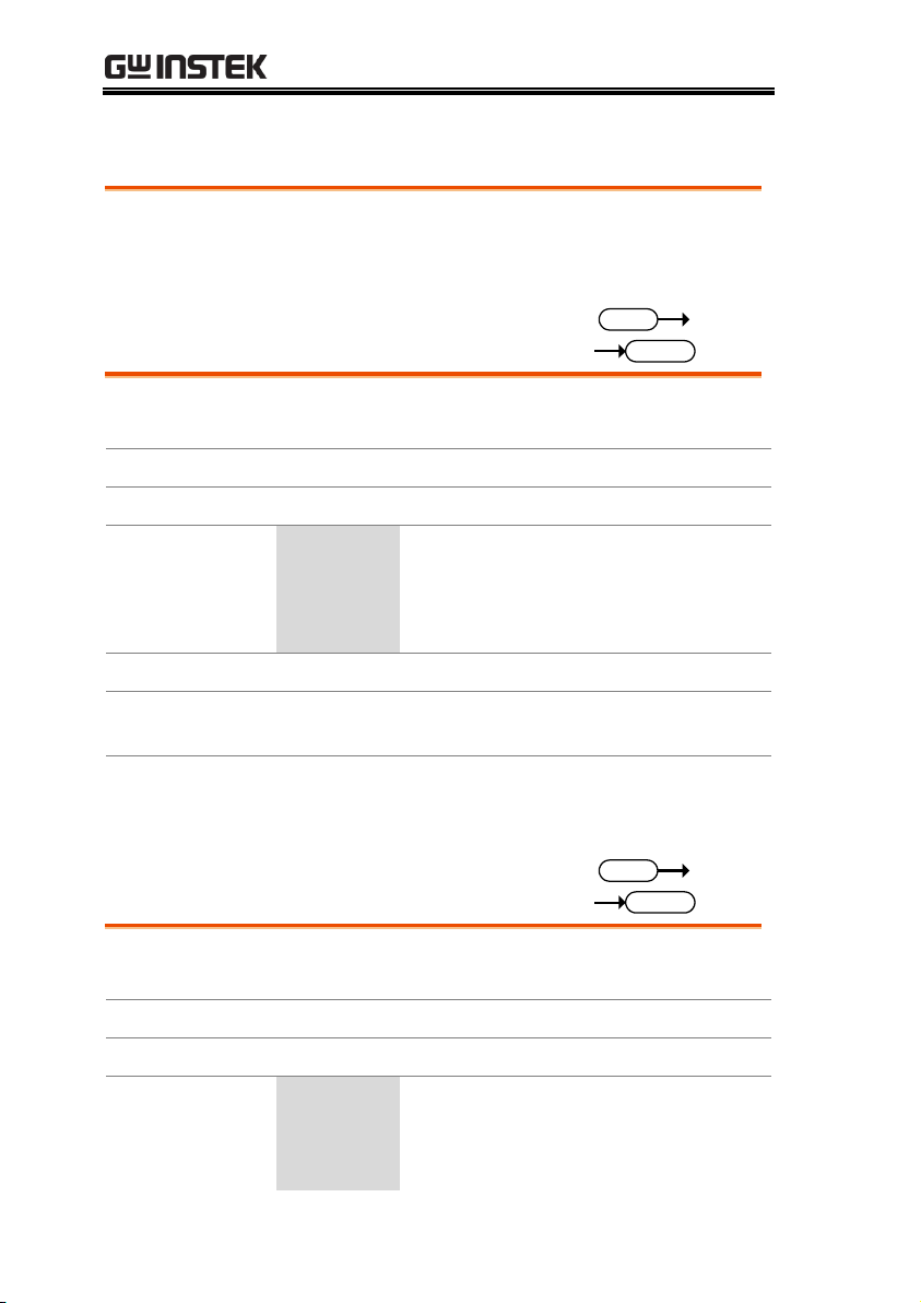
INTERFACE OVERVIEW
I MON OUT TRIG OUT
1.5 - 150V
175W
0 - 35A
P0
P1
P4
P7
CAL.
P2
P5
P8
Lock
P3
P6
P9
Utility
Local
File
0
1
4
7
2
5
8
3
6
9
EnterClear
Shift
Preset
Load
On/
Off
Main
Help
FUNC
Short
Air inlet LCD Display Power key
FUNC/File
Help/Utility
Short
Load On/Off
USB Port, Preset
and Shift keys
Number pad, Clear/
Lock and Enter keys
Main/Local
Scroll wheel
Function keys
Input
terminals
I MON OUT,
TRIG OUT
Appearance
Front Panel
PEL-3021/ PEL-3041
PEL-3021H/ PEL-3041H
3
Page 6

V
MON OUT
TRIG OUT
5 -800V
350W
0 -8.75A
P0
P1
P4
P7
CAL.
P2
P5
P8
Lock
P3
P6
P9
Utility
Local
File
0
1
4
7
2
5
8
3
6
9
EnterClear
Shift
Preset
Load
On/
Off
Main
Help
FUNC
Short
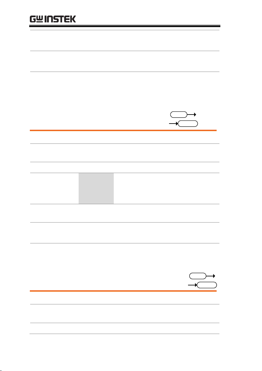
Air inlet LCD Display Power key
FUNC/File
Help/Utility
Short
Load On/Off
USB Port, Preset
and Shift keys
Number pad, Clear/
Lock and Enter keys
Main/Local
Scroll wheel
Function keys
Input
terminals
VMON OUT, I MON
OUT, TRIG OUT
I
MON OUT
A/ B
P0
P1
P4
P7
CAL.
P2
P5
P8
Lock
P3
P6
P9
Utility
Local
File
0
1
4
7
2
5
8
3
6
9
EnterClear
Shift
Preset
Load
On/
Off
Main
Help
FUNC
Short
TRIG
OUT
I MON
OUT
1.5 - 150V
1050W
0 - 70A
PEL-3111
PEL-3000(H) Programming Manual
4
Page 7

INTERFACE OVERVIEW
P0
P1
P4
P7
CAL.
P2
P5
P8
Lock
P3
P6
P9
Utility
Local
File
0
1
4
7
2
5
8
3
6
9
EnterClear
Shift
Preset
Load
On/
Off
Main
Help
FUNC
Short
TRIG OUT
I
MON OUT
5 - 800V
1050W
0 – 52.5A
V
MON OUT
A/B
LINK STBY
PEL-3111H
PEL-3211(H) Booster Pack
5
Page 8

PEL-3000(H) Programming Manual
47 - 63 Hz
90 VA MAX.
AC
100 - 120 VAC
200 - 240 VAC
FRAME CONT
J 1
J 2
SER. NO. LB
RS232C
GPIB
WARNING
TO AVOID ELECTRIC SHOCK THE POWER CORD
DO NOT REMOVE COVERS.
NO OPERATOR SERVICEABLE COMPONENTS INSIDE.
PROTECTIVE GROUNDING CONDUCTOR MUST BE
REFER SERVICING TO QUALIFIED PERSONNEL.
CONNECTED TO GROUND.
Remote sense
inputs
Frame control ports,
J1, J2
RS232C port
USB port
USB device
port
Exhaust fanGPIB Power socket
and switch
Rear panel
inputs
Rear Panel
PEL-3021/ PEL-3041
6
Page 9

INTERFACE OVERVIEW
47 - 63 Hz
90 VA MAX.
AC
100 - 120 VAC
200 - 240 VAC
FRAME CONT
J 1
J 2
RS232C
GPIB
Remote sense
inputs
Frame control ports,
J1, J2
RS232C port
USB port
USB device
port
Exhaust fan
GPIB
Power socket
and switch
Rear panel
inputs
VR1
VR2 VR3 VR4
V/I MON OUT
1
Monitor out
ports J3
Variable
resistor
P0
P1
P4
P7
CAL.
P2
P5
P8
Lock
P3
P6
P9
Utility
Local
File
0
1
4
7
2
5
8
3
6
9
EnterClear
Shift
Preset
Load
On/
Off
Main
Help
FUNC
Short
TRIG
OUT
I MON
OUT
1.5 - 150V
1050W
0 - 70A
PEL-3021H/ PEL-3041H
PEL-3111
7
Page 10

PEL-3000(H) Programming Manual
PEL-3111H
PEL-3211 Booster Pack
PEL-3211H Booster Pack
8
Page 11

INTERFACE OVERVIEW
USB
configuration
PC side connector
Type A, host
PEL-3000(H) side
connector
Rear panel Type B, slave
Speed
2.0 (full speed)
USB Class
USB CDC ACM
Note
Before USB can be used for remote control, it is
necessary to install the PEL-3000(H) USB device
driver, located on the accompanying User Manual CD.
Operation
1. Connect the USB cable to the rear panel USB B
port.
2. Press
Shift
+
Utility
Help
> Interface[F3] and set
the Interface setting to USB.
Operation
1. Ensure the PEL-3000(H) is off before
proceeding.
2. Connect a GPIB cable from a GPIB controller to
the GPIB port on the PEL-3000(H).
3. Turn the PEL-3000(H) on.
4. Press
Shift
+
Utility
Help
> Interface[F3] and set
the Interface setting to GPIB.
5. Set the GPIB address.
GPIB address
0-30
Interface Configuration
Configure to USB Remote Interface
Configure GPIB Interface
To use GPIB, the optional GPIB port must be installed.
9
Page 12

PEL-3000(H) Programming Manual
GPIB constraints
Maximum 15 devices altogether, 20m cable length,
2m between each device
Unique address assigned to each device
At least 2/3 of the devices turned On
No loop or parallel connection
Pin Assignment
112
1324
Pin
Signal
Pin
Signal
1-4
Data I/O 1-4
13-16
Data I/O 5-8
5 EOI
17
REN
6 DAV
18
Ground (DAV)
7 NRFD
19
Ground (NRFD)
8 NDAC
20
Ground (NDAC)
9 IFC
21
Ground (IFC)
10
SRQ
22
Ground (SRQ)
11
ATN
23
Ground (ATN)
12
SHIELD Ground
24
Single GND
RS232C
Configuration
Connector
DB-9, Male
Baud Rate
2400, 4800, 9600, 19200, 38400
Stop Bit
1, 2
Parity
None, Odd, Even
Operation
1. Connect an RS232C cable from the PC to the
rear panel RS232 port.
2. Press
Shift
+
Utility
Help
> Interface[F3] and
set the Interface setting to RS232.
3. Set the Baud Rate, Stop Bit and Parity settings.
Configure RS232C
10
Page 13

INTERFACE OVERVIEW
Pin Assignment
1 2 3 4 5
6 7 8 9
2: RxD (Receive data)
3: TxD (Transmit data)
5: GND
4, 6 - 9: No connection
PC Connection
Use a null modem connection as shown in the
diagram below.
Functionality
check
Invoke a terminal application such as Realterm.
For RS-232C, set the COM port, baud rate, stop bit,
data bit and parity accordingly.
To check the COM settings in Windows, see the
Device Manager. For example, in WinXP go to the
Control panel → System → Hardware tab.
Note
If you are not familiar with using a terminal
application to send/receive remote commands from
the serial port or via a USB connection, please page 12
(Using Realterm to Establish a Remote Connection)
for more information.
Run this query command via the terminal after the
instrument has been configured for
RS-232/USB remote control
*idn?
This should return the Manufacturer, Model
number, Serial number, and Firmware version in
PEL-3000(H)
PC
RxD
Pin 2 RxD
Pin 2 GND
Pin 5 GND
Pin 5 TxD
Pin 3 TxD
Pin
3
RS232C/USB Remote Control Function Check
11
Page 14

PEL-3000(H) Programming Manual
the following format.
GW-INSTEK,PEL-3000(H), XXXXXXXXXXXX,
V.X.X.X.X
Manufacturer: GW-INSTEK
Model number : PEL-3000(H)
Serial number : XXXXXXXXXXXX
Firmware version : V.X.X.X
Note
For further details, please see the programming
manual, available on the GW Instek web site @
www.gwinstek.com.
Background
Realterm is a terminal program that can be used to
communicate with a device attached to the serial
port of a PC or via an emulated serial port via USB.
The following instructions apply to version
1.99.0.27. Even though Realterm is used as an
example to establish a remote connection, any
terminal program can be used that has similar
functionality.
Note
Realterm can be downloaded on Sourceforge.net free
of charge.
For more information please see
http://realterm.sourceforge.net/
Operation
1. Download Realterm and install according to the
instructions on the Realterm website.
2. Connect the PEL-3000(H) via USB (page 9) or
via RS232 (page 10).
3. If using RS232, make note of the configured
baud rate, stop bits and parity.
4. Go to the Windows device manager and find
the COM port number for the connection.
For example, go to the Start menu > Control
Using Realterm to Establish a Remote Connection
12
Page 15

INTERFACE OVERVIEW
Panel > Device Manager
Double click the Ports icon to reveal the
connected serial port devices and the COM port
for the each connected device.
If using USB, the baud rate, stop bit and parity
settings can be viewed by right-clicking
connected device and selecting the Properties
option.
5. Start Realterm on the PC as an administrator.
Click:
Start menu>All Programs>RealTerm>realterm
Tip: to run as an administrator, you can right
click the Realterm icon in the Windows Start
menu and select the Run as Administrator
option.
6. After Realterm has started, click on the Port tab.
Enter the Baud, Parity, Data bits, Stop bits and
Port number configuration for the connection.
The Hardware Flow Control, Software Flow Control
options can be left at the default settings.
7. Press Open to connect to the PEL-3000(H).
13
Page 16

PEL-3000(H) Programming Manual
8. Click on the Send tab.
In the EOL configuration, check on the +CR and
+LF check boxes.
Enter the query:
*idn?
Click on Send ASCII.
9. The terminal display will return the following:
GW, PEL-3XXX(H),EXXXXXXX,VX.XX.XXX
(manufacturer, model, serial number, version)
10. If Realterm fails to connect to the PEL-3000(H),
please check all the cables and settings and try
again.
14
Page 17

INTERFACE OVERVIEW
Functionality
check
Please use the National Instruments Measurement
& Automation Controller software to confirm
GPIB functionality.
See the National Instrument website,
http://www.ni.com for details.
Note
For further details, please see the programming
manual, available on the GW Instek web site @
www.gwinstek.com.
Operation
1. Start the NI Measurement and
Automation Explorer (MAX)
program. Using Windows, press:
Start>All Programs>National
Instruments>Measurement & Automation
2. From the Configuration panel access;
My System>Devices and Interfaces>GPIB0
3. Press the Scan for Instruments button.
GPIB Function Check
15
Page 18

PEL-3000(H) Programming Manual
4. In the Connected Instruments panel the PEL-
3000(H) should be detected as Instrument 0 with
the address the same as that configured on the
PEL-3000(H).
5. Double click the Instrument 0 icon.
2
3
4
5
6. Click on Communicate with Instrument.
7. In the NI-488.2 Communicator window, ensure
*IDN? is written in the Send String: text box.
Click on the Query button to send the *IDN?
query to the instrument.
8. The String Received text box will display the
query return:
GW, PEL-3XXX(H),EXXXXXXX,VX.XX.XXX
(manufacturer, model, serial number, version)
16
Page 19

INTERFACE OVERVIEW
6
7
8
9. The function check is complete.
17
Page 20

PEL-3000(H) Programming Manual
Command Syntax ........................................................ 19
Command List ............................................................ 24
Status Register Overview .......................................... 203
Introduction to the Status Registers .................................................. 203
Configuration in the Status register ................................................... 204
Csummary Status Register Group ..................................................... 205
Operation Byte Register Group ......................................................... 207
Questionable Status Register Group ................................................. 208
Standard Event Status Register Group ............................................. 210
Status Byte Register Group ................................................................. 212
Error Messages ......................................................... 215
COMMAND OVERVIEW
The Command overview chapter lists all PEL3000(H) commands in functional order as well as
alphabetical order. The command syntax section
shows you the basic syntax rules you have to
apply when using commands.
18
Page 21

COMMAND OVERVIEW
Compatible
Standard
IEEE488.2
Partial compatibility
SCPI, 1999
Partial compatibility
Command
Structure
SCPI (Standard Commands for Programmable
Instruments) commands follow a tree-like
structure, organized into nodes. Each level of the
command tree is a node. Each keyword in a SCPI
command represents each node in the command
tree. Each keyword (node) of a SCPI command is
separated by a colon (:).
For example, the diagram below shows an SCPI
sub-structure and a command example.
:DYNamic:CRANge :VRANge
[:MODE]:CRANge
:MODE
Command types
There are a number of different instrument
commands and queries. A command sends
instructions or data to the unit and a query
receives data or status information from the unit.
Command types
Simple
A single command with/without
a parameter
Example
:CONFigure:SHORt HOLD
Command Syntax
19
Page 22

PEL-3000(H) Programming Manual
Query
A query is a simple or compound
command followed by a question
mark (?). A parameter (data) is
returned.
Example
:CONFigure:SHORt?
Compound
Two or more commands on the
same command line. Compound
commands are separated with
either a semi-colon (;) or a semicolon and a colon (;:).
A semi-colon is used to join two
related commands, with the
caveat that the last command
must begin at the last node of the
first command.
A semi-colon and colon are used
to combine two commands from
different nodes.
Example
CONFigure:VON
MAX;:CONFigure:VDELay MIN
Command Forms
Commands and queries have two different forms,
long and short. The command syntax is written
with the short form of the command in capitals
and the remainder (long form) in lower case.
The commands can be written in capitals or lowercase, just so long as the short or long forms are
complete. An incomplete command will not be
recognized.
Below are examples of correctly written
commands.
20
Page 23

COMMAND OVERVIEW
Long form
:CURRent:LEVel?
:CURRENT:LEVEL?
:current:level?
Short form
:CURR:LEV?
:curr:lev?
Square Brackets
Commands that contain square brackets indicate
that the contents are optional. The function of the
command is the same with or without the square
bracketed items, as shown below
For example for the query:
“[:CONFigure]:GNG [:PASS]?”
Both “:CONFigure:GNG:PASS?” and “:GNG?” are
both valid forms.
Command
Format
1.00A
1
2 3 4
:CURRent:Set
1. Command header
2. Space
3. Parameter 1
4. Unit or suffix.
Common
Unit Parameters
Type
Description
Example
<Boolean>
boolean logic
0, 1
<NR1>
integers
0, 1, 2, 3
<NR2>
decimal
numbers
0.1, 3.14, 8.5
<NR3>
floating point
4.5e-1, 8.25e+1
<NRf>
any of NR1, 2, 3
1, 1.5, 4.5e-1
21
Page 24

PEL-3000(H) Programming Manual
[MIN] (Optional
parameter)
For commands, this will set the
setting to the lowest value. This
parameter can be used in place of
any numerical parameter where
indicated.
For queries, it will return the
lowest possible value allowed for
the particular setting.
[MAX] (Optional
parameter)
For commands, this will set the
setting to the highest value. This
parameter can be used in place of
any numerical parameter where
indicated.
For queries, it will return the
highest possible value allowed
for the particular setting.
Unit Suffixes
(Optional
parameters)
Unit suffixes can be optionally
used with most NRf type input
parameters.
[A]
Amps
1.00A
[%]
Percentage
10%
[V]
Volts
5.00V
[W]
Watts
3.00W
[ms]
milliseconds
20ms
[mV]
Millivolts
150mV
[s]
Seconds
5s
[mS]
Reciprocal of
1000 ohms
20mS
[OHM]
Ohm
50OHM
[mA/us]
Millamps/
microsecond
100mA/us
[Hz]
Hertz
1000Hz
22
Page 25

COMMAND OVERVIEW
Note:
For [OHM] return values, an
infinite resistance (open) will be
returned as 9.9e37.
Message
Terminator
LF
Line feed code (0x0A)
23
Page 26

PEL-3000(H) Programming Manual
Common
Commands
*CLS ......................................................................................... 32
*ESE ......................................................................................... 32
*ESR ......................................................................................... 33
*IDN ........................................................................................ 33
*OPC ........................................................................................ 34
*RCL ......................................................................................... 34
*RST ......................................................................................... 35
*SAV ......................................................................................... 35
*SRE ......................................................................................... 35
*STB ......................................................................................... 36
*TRG ........................................................................................ 36
*TST ......................................................................................... 37
Trigger
Commands
:ABORt .................................................................................... 38
:INPut[:STATe]:TRIGgered ................................................ 39
:INITiate[:IMMediate] ........................................................... 39
:INITiate:CONTinuous ........................................................ 40
:TRIGger[:DELay]:TIME ..................................................... 40
:TRIGger[:PULSe]:WIDTh .................................................. 41
Input Commands
:INPut ....................................................................................... 42
:INPut:MODE ........................................................................ 42
[:INPut]:SHORt ...................................................................... 43
Measurement
Commands
:MEASure:CURRent ............................................................. 44
:MEASure:ETIMe .................................................................. 44
:MEASure:POWer ................................................................. 44
:MEASure:VOLTage ............................................................. 45
Fetch Subsystem
Commands
:FETCh:CURRent .................................................................. 46
:FETCh:POWer...................................................................... 46
:FETCh:VOLTage ................................................................. 46
Command List
24
Page 27

COMMAND OVERVIEW
Configure
Subsystem
Commands
[:CONFigure]:OCP ................................................................ 48
[:CONFigure]:OPP ................................................................ 49
[:CONFigure]:UVP ................................................................ 50
[:CONFigure]:UVP:TIME ................................................... 50
[:CONFigure]:OVP ............................................................... 51
[:CONFigure]:SSTart ............................................................. 52
[:CONFigure]:VON .............................................................. 52
[:CONFigure]:VDELay ......................................................... 53
:CONFigure:RESPonse ........................................................ 54
[:CONFigure]:CNTime ......................................................... 54
[:CONFigure]:COTime ......................................................... 55
[:CONFigure]:CRUnit ........................................................... 55
:CONFigure:DYNamic ......................................................... 56
:CONFigure:MEMory ........................................................... 56
:CONFigure:SHORt .............................................................. 57
:CONFigure:SHORt:SAFety................................................ 58
:CONFigure:SHORt:FUNCtion ......................................... 58
[:CONFigure]:GNG:MODE ............................................... 59
[:CONFigure]:GNG:H.......................................................... 60
[:CONFigure]:GNG:L .......................................................... 60
[:CONFigure]:GNG:C .......................................................... 61
[:CONFigure]:GNG:DTIMe ............................................... 62
[:CONFigure]:GNG:SPECtest ............................................ 62
[:CONFigure]:GNG[:PASS] ................................................ 63
Parallel
Command
[:CONFigure]:PARallel ......................................................... 64
Step Resolution
Commands
:CONFigure:STATus ............................................................ 65
[:CONFigure]:STEP:CC ....................................................... 66
[:CONFigure]:STEP:CCH .................................................... 66
[:CONFigure]:STEP:CCM ................................................... 67
[:CONFigure]:STEP:CCL..................................................... 67
[:CONFigure]:STEP:CR ....................................................... 68
[:CONFigure]:STEP:CRH .................................................... 68
[:CONFigure]:STEP:CRM ................................................... 69
[:CONFigure]:STEP:CRL ..................................................... 70
[:CONFigure]:STEP:CV ....................................................... 70
[:CONFigure]:STEP:CVH ................................................... 71
[:CONFigure]:STEP:CVL .................................................... 71
[:CONFigure]:STEP:CP........................................................ 72
25
Page 28

PEL-3000(H) Programming Manual
[:CONFigure]:STEP:CPH .................................................... 72
[:CONFigure]:STEP:CPM .................................................... 73
[:CONFigure]:STEP:CPL ..................................................... 74
External Control
Commands
[:CONFigure]:EXTernal[:CONTrol] .................................. 75
[:CONFigure]:EXTernal:CV ................................................ 75
[:CONFigure]:EXTernal:LOADonin ................................. 76
Mode Subsystem
Commands
:MODE .................................................................................... 77
[:MODE]:CRANge ................................................................ 77
[:MODE]:VRANge ................................................................ 78
[:MODE]:RESPonse ............................................................. 78
[:MODE]:DYNamic .............................................................. 79
Current
Subsystem
Commands
:CURRent[:VA] ....................................................................... 80
:CURRent[:VA]:TRIGgered ................................................. 81
:CURRent:VB ......................................................................... 81
:CURRent:SRATe .................................................................. 82
:CURRent:L1 ........................................................................... 82
:CURRent:L2 ........................................................................... 83
:CURRent:SET ....................................................................... 84
:CURRent:LEVel .................................................................... 84
:CURRent:RISE ...................................................................... 85
:CURRent:FALL .................................................................... 86
:CURRent:T1 .......................................................................... 86
:CURRent:T2 .......................................................................... 87
:CURRent:FREQuency ......................................................... 88
:CURRent:DUTY ................................................................... 88
:CURRent:RECall ................................................................... 89
Resistance
Subsystem
Commands
:RESistance[:VA] .................................................................... 90
:RESistance[:VA]:TRIGgered .............................................. 91
:RESistance:VB ....................................................................... 91
:RESistance:SRATe ................................................................ 92
:RESistance:L1 ........................................................................ 93
:RESistance:L2 ........................................................................ 93
:RESistance:SET ..................................................................... 94
:RESistance:LEVel ................................................................. 95
:RESistance:RISE ................................................................... 95
:RESistance:FALL .................................................................. 96
26
Page 29

COMMAND OVERVIEW
:RESistance:T1........................................................................ 97
:RESistance:T2........................................................................ 97
:RESistance:FREQuency ...................................................... 98
:RESistance:DUTY ................................................................ 99
:CONDuctance[:VA] ............................................................. 99
:CONDuctance[:VA]:TRIGgered ..................................... 100
:CONDuctance:VB .............................................................. 100
:CONDuctance:L1 ............................................................... 101
:CONDuctance:L2 ............................................................... 102
:CONDuctance:SET ........................................................... 103
:CONDuctance:RECall ....................................................... 103
:RESistance:RECall .............................................................. 104
Voltage
Subsystem
Commands
:VOLTage[:VA] .................................................................... 105
:VOLTage:VB ....................................................................... 105
:VOLTage:RECall ................................................................ 106
Power Subsystem
Commands
:POWer[:VA] ........................................................................ 107
:POWer:VB ........................................................................... 108
:POWer:L1 ............................................................................ 108
:POWer:L2 ............................................................................ 109
:POWer:SET ......................................................................... 110
:POWer:LEVel ..................................................................... 110
:POWer:T1 ............................................................................ 111
:POWer:T2 ............................................................................ 112
:POWer:FREQuency ........................................................... 112
:POWer:DUTY .................................................................... 113
:POWer:RECall .................................................................... 114
Program
Commands
:FUNCtion[:COMPlete][:RING]:TIME .......................... 115
:PROGram:STATe .............................................................. 116
:PROGram ............................................................................ 117
:PROGram[:RECall]:DEFault ........................................... 118
:PROGram:STARt ............................................................... 118
:PROGram:STEP................................................................. 119
:PROGram:MEMory ........................................................... 119
:PROGram:RUN ................................................................. 120
:PROGram:ONTime ........................................................... 120
:PROGram:OFFTime ......................................................... 121
:PROGram:PFTime ............................................................. 121
:PROGram:STIMe ............................................................... 122
27
Page 30

PEL-3000(H) Programming Manual
[:PROGram]:CHAin:STARt .............................................. 123
[:PROGram]:CHAin ............................................................ 123
[:PROGram]:CHAin:P2P.................................................... 124
[:PROGram]:CHAin[:RECall]:DEFault ........................... 125
:PROGram:SAVE ................................................................ 125
Normal sequence
Commands
:NSEQuence:STATe ........................................................... 126
:NSEQuence ......................................................................... 127
:NSEQuence:STARt ............................................................ 129
:NSEQuence:NUMBer ....................................................... 130
:NSEQuence:MEMO .......................................................... 130
:NSEQuence:MODE .......................................................... 131
:NSEQuence:RANGe ......................................................... 131
:NSEQuence:LOOP ............................................................ 132
:NSEQuence:LLOAD ......................................................... 133
:NSEQuence:LAST ............................................................. 133
:NSEQuence:CHAin ........................................................... 134
:NSEQuence:EDIT ............................................................. 134
:NSEQuence:EDIT:POINt ............................................... 136
:NSEQuence:EDIT:END .................................................. 136
:NSEQuence[:DELet]:ALL ................................................ 136
:NSEQuence:SAVE ............................................................. 137
:NSEQuence:COTime ........................................................ 137
Fast sequence
Commands
:FSEQuence:STATe ............................................................ 138
:FSEQuence .......................................................................... 139
:FSEQuence:MEMO ........................................................... 140
:FSEQuence:MODE ........................................................... 141
:FSEQuence:RANGe .......................................................... 141
:FSEQuence:LOOP ............................................................. 142
:FSEQuence:TBASe ............................................................ 143
:FSEQuence:LLOAD .......................................................... 143
:FSEQuence:LAST .............................................................. 144
:FSEQuence:RPTStep ......................................................... 144
:FSEQuence:EDIT .............................................................. 145
:FSEQuence:EDIT:POINt ................................................ 146
:FSEQuence:EDIT:END ................................................... 146
:FSEQuence[:DELet]:ALL ................................................. 146
:FSEQuence[:EDIT]:FILL ................................................. 147
:FSEQuence:SAVE .............................................................. 147
28
Page 31

COMMAND OVERVIEW
OCP test
Commands
:OCP:STATe ......................................................................... 149
:OCP:EDIT[:CHANnel] ..................................................... 150
:OCP[:CHANnel]:NUMBer ............................................... 151
:OCP:MEMO ....................................................................... 151
:OCP[:CHANnel]:RANGe ................................................. 152
:OCP[:CHANnel]:STARt ................................................... 152
:OCP[:CHANnel]:END...................................................... 153
:OCP[:CHANnel]:STEP:CURRent .................................. 153
:OCP[:CHANnel]:STEP:TIME ......................................... 154
:OCP[:CHANnel]:DELay ................................................... 154
:OCP[:CHANnel]:TRIGger ............................................... 155
:OCP[:CHANnel]:LAST ..................................................... 155
:OCP:CHANnel:STATus ................................................... 156
:OCP:RESult ......................................................................... 156
:OCP:RUN ............................................................................ 157
OPP test
Command
:OPP:STATe ......................................................................... 158
:OPP:EDIT[:CHANnel] ..................................................... 159
:OPP[:CHANnel]:NUMBer ............................................... 160
:OPP:MEMO ........................................................................ 160
:OPP[:CHANnel]:RANGe ................................................. 161
:OPP[:CHANnel]:STARt .................................................... 161
:OPP[:CHANnel]:END ...................................................... 162
:OPP[:CHANnel]:STEP:WATT ....................................... 163
:OPP[:CHANnel]:STEP:TIME ......................................... 163
:OPP[:CHANnel]:DELay ................................................... 164
:OPP[:CHANnel]:TRIGger................................................ 164
:OPP[:CHANnel]:LAST ..................................................... 165
:OPP:CHANnel:STATus.................................................... 166
:OPP:RESult ......................................................................... 166
:OPP:RUN ............................................................................ 166
BATT test
Command
:BATTery:STATe ................................................................. 167
:BATT:EDIT ........................................................................ 168
:BATTery [:CHANnel]:NUMBer ...................................... 169
:BATTery:MEMO ............................................................... 170
:BATTery:MODE ................................................................ 170
:BATTery:RANGe ............................................................... 171
:BATTery:VALue ................................................................. 171
:BATTery:RISE .................................................................... 172
:BATTery:FALL ................................................................... 172
29
Page 32

PEL-3000(H) Programming Manual
:BATTery:STOP:VOLTage ................................................ 173
:BATTery:STOP:TIME ...................................................... 174
:BATTery:STOP:AH ........................................................... 174
:BATTery:DATalog:TIMer ................................................ 175
:BATT:CHANnel:STATus ................................................. 175
:BATT:RESult ....................................................................... 176
:BATT:RUN .......................................................................... 176
Utility Commands
:UTILity:SYSTem................................................................. 177
:UTILity:LOAD ................................................................... 178
:UTILity:LOAD:MODE .................................................... 178
:UTILity:LOAD:RANGe ................................................... 179
:UTILity:TIME ..................................................................... 179
:UTILity:KNOB ................................................................... 180
:UTILity:SPEAker ................................................................ 181
:UTILity:ALARm ................................................................. 181
:UTILity:UNReg ................................................................... 182
:UTILity:GNG ...................................................................... 183
:UTILity:CONTrast ............................................................. 183
:UTILity:BRIghtness............................................................ 184
:UTILity:LANGuage ........................................................... 184
:UTILity:REMote ................................................................. 185
:UTILity:REMote:MODE .................................................. 185
Interface
Commands
:UTILity:INTerface .............................................................. 186
:UTILity:BRATe ................................................................... 186
:UTILity:SBIT ....................................................................... 187
:UTILity:PARity ................................................................... 187
File Commands
:MEMory:SAVE ................................................................... 189
:MEMory:RECall .................................................................. 189
:PREset:SAVE ...................................................................... 190
:PREset:RECall ..................................................................... 190
:SETup:SAVE ....................................................................... 190
:SETup:RECall...................................................................... 190
:FACTory[:RECall] .............................................................. 191
:USER[:DEFault]:SAVE ..................................................... 191
:USER[:DEFault]:RECall.................................................... 191
30
Page 33

COMMAND OVERVIEW
SCPI Status
Commands
:SYSTem:ERRor .................................................................. 192
:STATus:PRESet .................................................................. 192
Csummary Status
Commands
:STATus:CSUMmary:CONDition .................................... 194
:STATus:CSUMmary:ENABle .......................................... 194
:STATus:CSUMmary[:EVENt] ......................................... 195
:STATus:CSUMmary:NTRansition .................................. 195
:STATus:CSUMmary:PTRansition ................................... 195
Operation Status
Commands
:STATus:QUEStionable:CONDition .............................. 200
:STATus:QUEStionable:ENABle ..................................... 200
:STATus:QUEStionable[:EVENt] .................................... 201
:STATus:QUEStionable:NTRansition ............................. 201
:STATus:QUEStionable:PTRansition .............................. 201
Questionable
Status
Commands
:STATus:QUEStionable:CONDition .............................. 200
:STATus:QUEStionable:ENABle ..................................... 200
:STATus:QUEStionable[:EVENt] .................................... 201
:STATus:QUEStionable:NTRansition ............................. 201
:STATus:QUEStionable:PTRansition .............................. 201
31
Page 34

PEL-3000(H) Programming Manual
*CLS ......................................................................................... 32
*ESE ......................................................................................... 32
*ESR ......................................................................................... 33
*IDN ........................................................................................ 33
*OPC ........................................................................................ 34
*RCL ......................................................................................... 34
*RST ......................................................................................... 35
*SAV ......................................................................................... 35
*SRE ......................................................................................... 35
*STB ......................................................................................... 36
*TRG ........................................................................................ 36
*TST ......................................................................................... 37
*CLS
Set
Description
Clears all Event registers and queues.
Syntax
*CLS
Example
*CLS
Clears all Event registers and queues.
*ESE
Set
Query
Description
Queries or sets the Standard Event Status Enable
register. The Standard Event Status Enable
register determines which events can set the Event
Summary bit (ESB) in the Status Byte Register.
Any bits that are set to 1 enable the corresponding
event. Each event is represented by a bit in the
Standard Event Status Enable register.
Refer to section “Standard Event Status register
group” on page 210 for more information on bit.
Syntax
*ESE <NRf>
Query Syntax
*ESE?
Common Commands
32
Page 35

COMMAND OVERVIEW
Parameter
<NR1> 1
Sets the Standard Event Status Enable
register.
Return parameter
Return in "<NR1>" the set value of the Standard
Event Status Enable register.
Example
*ESE 8
Sets bit 3 of the ESE register.
Query example
*ESE?
>12
Bits 2 and 3 are set in the Standard Event Status
Enable register.
*ESR
Set
Query
Description
Reads the Standard Event Status register. This
command will also clear the Standard Event
Status register.
Refer to section “Standard Event Status register
group” on page 210 for more information on bit.
Query Syntax
*ESR?
Return parameter
Return in "<NR1>" the set value of the Standard
Event Status register.
Query example
*ESR?
>48
Bits 5 and 6 are set in the Standard Event register.
*IDN
Query
Description
Queries the manufacturer, model number, serial
number, and firmware version of the instrument.
Query Syntax
*IDN?
33
Page 36

PEL-3000(H) Programming Manual
Return parameter
<string>
<string>
<NR1>
<string>
Returns the manufacturer name.
Returns the model number.
Returns the serial number.
Returns the version of firmware
Query example
* IDN?
> GWInstek, PEL-3111H,12345678,V1.01.001
It is a response equipment manufacturer, model
number, serial number, and firmware version.
*OPC
Set
Query
Description
This command sets the OPC (Operation
Command Bit) bit (bit 0) of the Standard Event
Status Register after the instrument has completed
all pending operations. The query will return the
status of the OPC bit.
Syntax
*OPC
Query Syntax
*OPC?
Return parameter
1
Operation complete
Example
*OPC
Query Example
*OPC?
>1
Indicates that all pending operations are complete.
*RCL
Set
Description
The Recall Instrument State command restores the
instrument settings from a previously saved
memory setting.
Syntax
*RCL <NR1>
Parameter
<NR1>
Memory number 1 to 256
Example
*RCL 20
Recall setting memory 20.
34
Page 37

COMMAND OVERVIEW
Same function
command
:MEMory:RECall
*RST
Set
Description
Resets the unit. This is command forces the
ABORt, and *CLS
Syntax
*RST
Example
*RST
Resets the unit.
*SAV
Set
Description
The Save Instrument State command saves the
instrument settings to one of the memory setting
slots.
Syntax
*SAV <NR1>
Parameter
<NR1>
Memory number 1 to 256
Example
*SAV 20
Saves the current setting to memory 20.
Same function
command
:MEMory:SAVe
*SRE
Set
Query
Description
Queries or sets the Service Request Enable
register. The Service Request Enable register
determines which events in the Status Byte
register can set the Master Summary bit (MSB) in
the Status Byte Register. Any bits that are set to 1
will cause the MSS bit to be set.
Refer to section “Status byte register group” on
page 212 for more information on bit.
Syntax
*SRE <NRf>
35
Page 38

PEL-3000(H) Programming Manual
Query Syntax
*SRE?
Parameter
<NR1>
Sets the set value of the Service Request
Enable register.
Return parameter
Return in "<NR1>" the set value of the Service
Request Enable register.
Example
*SRE 8
Sets bit 3 of the Service Request Enable register.
Query example
*SRE?
>12
Bits 2 and 3 are set in the Service Request Enable
register.
*STB
Set
Query
Description
Reads the Status Byte register. This command will
not clear the Status Byte register.
If the Master Summary Status bit (MSS) is set, it
indicates that there is a reason for a service
request.
Refer to section “Status byte register group” on
page 212 for more information on bit.
Query Syntax
*STB?
Return parameter
Return in "<NR1>" the value of the Status Byte
register.
Query example
*STB?
>36
Bits 2 and 5 are set in the Status Byte register.
*TRG
Set
Description
This command triggers the unit.
Syntax
*TRG
36
Page 39

COMMAND OVERVIEW
Example
*TRG
Issue the enforcement trigger.
Related
Commands
:INITiate:CONTinuous, :INITiate[:IMMediate]
*TST
Set
Query
Description
This command is a standard SCPI self-test
command. The PEL-3000(H) does not perform any
self-tests so will always return 0 (pass) for this
command.
Query Syntax
*TST?
Return parameter
<NR1>
Pass
Query example
*TST?
>0
37
Page 40

PEL-3000(H) Programming Manual
:ABORt .................................................................................... 38
:INPut[:STATe]:TRIGgered ................................................. 39
:INITiate[:IMMediate] ........................................................... 39
:INITiate:CONTinuous ........................................................ 40
:TRIGger[:DELay]:TIME ..................................................... 40
:TRIGger[:PULSe]:WIDTh .................................................. 41
Idle state
Trigger Wait
state
:INIT:CONT
PEL-3000H
power on
Triggered
ON
OFF
*RST,
ABORt
:INITate[:IMMediate],
:INITiate:CONTinuous ON
*TRG,
manual trigger
:ABORt
Set
Description
Clears the trigger wait status and returns to the
idle state.
Query Syntax
:ABORt
Example
:ABOR
Clears the trigger wait status.
Trigger Commands
Trigger States
38
Page 41

COMMAND OVERVIEW
:INPut[:STATe]:TRIGgered
Set
Query
Description
Sets whether to turn on the load input when the
trigger is activated. Sets when PEL-3000H is on
idle state.
Syntax
:INPut[:STATe]:TRIGgered {<Boolean>|OFF | ON }
Query Syntax
:INPut[:STATe]:TRIGgered?
Parameter
OFF or 0
Not change the load input in when the
trigger active.
ON or 1
Turn on the load input in when the
trigger active.
Example
:INP:TRIG ON
Turn on the load input in when the trigger active.
Related
Commands
*TRG, :INITiate:CONTinuous, :INITiate[:IMMediate]
:INITiate[:IMMediate]
Set
Description
Sets the trigger to the wait state. If the trigger is
activated, the trigger will automatically go to the
idle state.
Query Syntax
:INITiate[:IMMediate]
Example
:INIT
Sets the trigger to the wait state.
Related
Commands
*TRG, :INPut[:STATe]:TRIGered,
:CURRent[:VA]:TRIGgered,
:RESistance[:VA]:TRIGgered
39
Page 42

PEL-3000(H) Programming Manual
:INITiate:CONTinuous
Set
Query
Description
Sets or queries for state of the continuous waiting
for the trigger.
Note
Release of the trigger wait state requires activation of
the trigger.
Syntax
:INITiate:CONTinuous {<Boolean>|OFF | ON }
Query Syntax
:INITiate:CONTinuous?
Parameter
OFF or 0
Remove the continuous waiting for the
trigger.
ON or 1
Sets to continuous waiting for the
trigger.
Example
:INIT:CONT ON
Sets to continuous waiting for the trigger.
Query example
:INITiate:CONT?
>1
Setting in a continuous wait for trigger, and wait for
the trigger.
Related
Commands
*TRG, :INPut[:STATe]:TRIGered,
:CURRent[:VA]:TRIGgered,
:RESistance[:VA]:TRIGgered
:TRIGger[:DELay]:TIME
Set
Query
Description
The command determines how long to delay any
action after a trigger is received. Equivalent to
using the “Trig In Delay” setting on the front
panel.
Syntax
:TRIGger[:DELay]:TIME <NR2>|MINimum|MAXimum
Query Syntax
:TRIGger[:DELay]:TIME? [MINimum|MAXimum]
Parameter
<NR2>
0 ~ 0.005s (0 ~ 5000us)
MINimum
Minimum delay time
40
Page 43

COMMAND OVERVIEW
MAXimum
Maximum delay time
Return parameter
Returns the delay time
Example
:TRIG:TIME 0.005
Sets the trigger in delay to 5ms.
Query example
:TRIG:TIME?
>0.0050000
Returns the delay time in seconds.
:TRIGger[:PULSe]:WIDTh
Set
Query
Description
Sets and queries for the trigger output signal’s
pulse width.
Syntax
:TRIGger[:PULSe]:WIDTh
<NR2>|MINimum|MAXimum
Query Syntax
:TRIGger[:PULSe]:WIDTh? [MINimum|MAXimum]
Parameter
<NR2>
0.0000025~0.005s (2.5us ~ 5000us)
MINimum
MAXimum
Return parameter
Returns the pulse width
Example
:TRIG:WIDT 0.005
Sets the trigger pulse width to 5ms.
Query example
TRIG:WIDT?
>0.0050000
Returns the pulse width of the trigger output.
41
Page 44
PEL-3000(H) Programming Manual
:INPut ....................................................................................... 42
:INPut:MODE ........................................................................ 42
[:INPut]:SHORt ...................................................................... 43
:INPut
Set
Query
Description
Sets and queries for the status of the load. Setting
stop and restart of program, sequence, OCP test.
Syntax
:INPut {<Boolean>|OFF | ON }
Query Syntax
:INPut?
Parameter
OFF or 0
Sets the off the load input setting. Sets
stop of program, sequence, OCP test.
ON or 1
Sets the on the load input setting. Sets
restart of program, sequence, OCP test.
Return parameter
Return in "<Boolean>" the set value of the load input.
Example
:INP ON
the on the load input setting.
Query example
:INP?
>1
Load input setting is on.
:INPut:MODE
Set
Query
Description
Sets and queries for the operating function of the
load.
Syntax
:INPut:MODE{LOAD|PROG|NSEQ|FSEQ}
Query Syntax
:INPut:MODE
Parameter
LOAD
Sets the manual operation.
PROG
Sets the program function.
NSEQ
Sets the normal sequence function.
Input Commands
42
Page 45

COMMAND OVERVIEW
FSEQ
Sets the fast sequence function.
Example
:INPut:MODE LOAD
Sets to the manual operation.
Query example
:INPut:MODE?
>LOAD
Mode of operation is the manual operation.
[:INPut]:SHORt
Set
Query
Description
Sets and queries for the input terminals state
(open or short).
Syntax
[:INPut]:SHORt {<Boolean>|OFF | ON }
Query Syntax
[:INPut]:SHORt?
Parameter
OFF or 0
Sets the open.
ON or 1
Sets the short.
Return parameter
Return in "<Boolean>" the input terminals state.
Example
:SHOR ON
Sets the short.
Query example
:SHOR?
>1
The input terminals state is short.
43
Page 46

PEL-3000(H) Programming Manual
:MEASure:CURRent .............................................................. 44
:MEASure:ETIMe .................................................................. 44
:MEASure:POWer ................................................................. 44
:MEASure:VOLTage ............................................................. 45
:MEASure:CURRent
Set
Query
Description
Query of current measurement.
Query Syntax
:MEASure:CURRent?
Return parameter
Return the current measurement (<NR2>). The unit is
the [A].
Query example
:MEAS:CURR?
>0.50000
Current measurement is 0.5A.
:MEASure:ETIMe
Set
Query
Description
Query of the elapsed time of the load-on.
Query Syntax
:MEASure:ETIMe?
Return parameter
Return the elapsed time (<NR2>) of the load-on. The
unit is the seconds.
Query example
:MEAS:ETIM?
>10.0
The elapsed time of the load-on is 10 seconds.
:MEASure:POWer
Set
Query
Description
Query of power measurement.
Query Syntax
:MEASure:POWer?
Return parameter
Return the power measurement (<NR2>). The unit is
the [W].
Measurement Commands
44
Page 47

COMMAND OVERVIEW
Query example
:MEAS:POWer?
>15.00000
Power measurement is 15W.
:MEASure:VOLTage
Set
Query
Description
Query of voltage measurement.
Query Syntax
:MEASure:VOLTage?
Return parameter
Return the voltage measurement (<NR2>). The unit is
the [V].
Query example
:MEAS:VOLT?
>5.00000
Voltage measurement is 5V.
45
Page 48

PEL-3000(H) Programming Manual
:FETCh:CURRent .................................................................. 46
:FETCh:POWer ...................................................................... 46
:FETCh:VOLTage ................................................................. 46
:FETCh:CURRent
Set
Query
Description
This query returns the real-time current of the
load input.
Query syntax
:FETCh:CURRent?
Return parameter
Returns the real-time current .The unit is [A]
Query example
:FETC:CURR?
>0.5000
The load has a current of 0.5 amps at the input.
:FETCh:POWer
Set
Query
Description
This query returns the real-time power of the load
input.
Query syntax
:FETCh:POWer?
Return parameter
Returns the real-time power. The unit is [W].
Query example
:FETC:POW?
>15.00000
The load is at 15 watts.
:FETCh:VOLTage
Set
Query
Description
This query returns the real-time voltage of the
load input.
Query syntax
:FETCh:VOLTage?
Return parameter
Returns the real-time voltage. The unit is [V].
Fetch Subsystem
46
Page 49

COMMAND OVERVIEW
Query example
:FETC:VOLT?
>5.00000
The load has a voltage of 5 volts at the input.
47
Page 50

PEL-3000(H) Programming Manual
[:CONFigure]:OCP ................................................................ 48
[:CONFigure]:OPP ................................................................ 49
[:CONFigure]:UVP ................................................................ 50
[:CONFigure]:UVP:TIME .................................................... 50
[:CONFigure]:OVP ................................................................ 51
[:CONFigure]:SSTart ............................................................. 52
[:CONFigure]:VON ............................................................... 52
[:CONFigure]:VDELay ......................................................... 53
:CONFigure:RESPonse......................................................... 54
[:CONFigure]:CNTime ......................................................... 54
[:CONFigure]:COTime ......................................................... 55
[:CONFigure]:CRUnit ........................................................... 55
:CONFigure:DYNamic ......................................................... 56
:CONFigure:MEMory ........................................................... 56
:CONFigure:SHORt .............................................................. 57
:CONFigure:SHORt:SAFety ................................................ 58
:CONFigure:SHORt:FUNCtion ......................................... 58
[:CONFigure]:GNG:MODE ............................................... 59
[:CONFigure]:GNG:H .......................................................... 60
[:CONFigure]:GNG:L ........................................................... 60
[:CONFigure]:GNG:C .......................................................... 61
[:CONFigure]:GNG:DTIMe................................................ 62
[:CONFigure]:GNG:SPECtest ............................................ 62
[:CONFigure]:GNG[:PASS] ................................................. 63
[:CONFigure]:OCP
Set
Query
Description
Sets and queries for the OCP trip settings. The
OCP limit can be set to a specific value or the trip
setting can be set to either limit the current or to
turn the load off.
Syntax
[:CONFigure]:OCP {<NRf>[ A ] | MINimum |
MAXimum | LIMit | LOFF}
Query Syntax
[:CONFigure]:OCP?
Configure Subsystem Commands
48
Page 51

COMMAND OVERVIEW
<NRf>[A]
MINimum
MAXimum
LIMit
Current limit value.
Minimum current limit value.
Maximum current limit value.
Limit the current.
LOFF
Turn the load off.
Return parameter
Returns OCP setting followed by the OCP value, by
the "{Load off | LIMIT},<NR2>" string.
Example1
:OCP LIM
Sets the OCP setting to limit.
Example2
:OCP 19.250
Sets the OCP value to 19.25A.
Query example
:OCP?
>LIMIT, 19.250
The OCP setting is LIMIT and the OCP value is
19.25A.
[:CONFigure]:OPP
Set
Query
Description
Sets or queries for the OPP trip settings. The OPP
limit can be set to a specific value or the trip
setting can be set to either limit the power or to
turn the load off.
Syntax
[:CONFigure]:OPP {<NRf> [W] | MINimum |
MAXimum | LIMit | LOFF}
Query Syntax
[:CONFigure]:OPP?
Parameter
<NRf>[W]
MINImum
MAXImum
LIMit
LOFF
Power limit value.
Minimum power limits value.
Maximum power limits value.
Limit the power
Turn the load off
Return parameter
Returns a string with OPP setting followed by the
OPP value, by the "{Load off | LIMIT},<NR2>" string.
49
Page 52
PEL-3000(H) Programming Manual
Example1
:OPP LIM
Sets the OCP setting to limit.
Example2
:OPP 10.000
Sets the OPP value to 10W.
Query example
:OPP?
>LIMIT, 10.000
The OPP setting is limited and the OPP value is
10.000W.
[:CONFigure]:UVP
Set
Query
Description
Sets or queries for the UVP trip settings.
Syntax
[:CONFigure]:UVP {<NRf>[ V ] |MINimum |
MAXimum }
Query Syntax
[:CONFigure]:UVP?
Parameter
<NRf>[V]
MINimum
MAXimum
Under voltage limit value. ; 0 = OFF
Minimum value. (UVP setting is OFF.)
Maximum value.
Return parameter
Return the set value of the UVP, by the "<NR2>"
string
Example1
:UVP 10.0
Sets the UVP setting to 10V.
Query example
:UVP?
> 10.0
The UVP setting is 10V.
[:CONFigure]:UVP:TIME
Set
Query
Description
Sets and queries for the UVP ring time setting.
Syntax
:[CONFigure]:UVP:TIME {<NR1> | MINimum |
MAXimum | INFinity}
Query Syntax
:[CONFigure]:UVP:TIME? [MINimum | MAXimum]
50
Page 53

COMMAND OVERVIEW
Parameter
<NR1>[s]
MINimum
MAXimum
INFinity
The ring time in seconds(0~600); 0 =
OFF
Minimum ring time
Maximum ring time
Sets the ring time to infinity.
Return parameter
<NR1>
Infinity
OFF
The ring time in seconds
Infinite
Function complete ring time is off.
Example
:UVP:TIME 5
Sets the UVP ring time to 5 seconds.
Query example
:UVP:TIME?
>5
The UVP ring time is 5 seconds.
[:CONFigure]:OVP
Set
Query
Description
Sets or queries for the OVP trip settings.
Syntax
[:CONFigure]:OVP {<NRf>[ V ] | MINimum|
MAXimum}
Query Syntax
[:CONFigure]:OVP?
Parameter
<NRf>[V]
MINimum
MAXimum
Over voltage limit value.
Minimum value.
Maximum value. (OVP setting is OFF.)
Return parameter
Return the set value of the OVP, by the "{<NR2> |
OFF}" string. "OFF" is a function off.
Example1
:OVP 10.00
Sets the OVP setting to 10V.
Query example
:OVP?
> 10.0000
The OVP setting is 10.0000V.
51
Page 54

PEL-3000(H) Programming Manual
[:CONFigure]:SSTart
Set
Query
Description
Sets and queries for the Soft Start time setting.
Syntax
[:CONFigure]:SSTart {<NRf>[s] | MINimum|
MAXimum | OFF}
Query Syntax
[:CONFigure]:SSTart?
Parameter
<NRf>[s]
MINimum
MAXimum
OFF
The soft start time in seconds.
Minimum time = 0 second
Maximum time
OFF = 0 second
Return parameter
Return the set value of the soft-start time, by the
"{<NR2> | OFF}" string. "OFF" is a function off.
Example
:SST OFF
Turns the soft start function off.
Query example
:SST?
>OFF
The soft start function is off.
[:CONFigure]:VON
Set
Query
Description
Sets and queries for the Von voltage settings and
latch.
Syntax
[:CONFigure]:VON {<NRf>[ V ] | MINimum|
MAXimum | LON | LOFF}
Query Syntax
[:CONFigure]:VON?
Parameter
{<NRf>[V]
MINimum
MAXimum
LON
LOFF
The Von voltage value.
Minimum Von voltage value.
Maximum Von voltage value.
Latch on
Latch off
52
Page 55

COMMAND OVERVIEW
Return parameter
Return the Von value and the mode of operation, by
the " Latch:{OFF | ON},<NR2>" string.
Example
:VON 10.0V LON
Sets the Von voltage value to 10.0 volts. And Von
latch ON.
Query example
:VON?
>Latch OFF, 0.00
The Von voltage value is 0V.
[:CONFigure]:VDELay
Set
Query
Description
Sets and queries for the Von Delay settings in
seconds.
Syntax
[:CONFigure]:VDELay {<NRf>[s] | MINimum |
MAXimum}
Query Syntax
[:CONFigure]:VDELay?
Parameter
<NRf>[s]
OFF
MINimum
MAXimum
The delay time in seconds
Disable the delay time
Minimum delay time
Maximum delay time
Return parameter
Return the set value of the delay time, by the
"{<NR2> | OFF}" string. "OFF" is a function off.
Example 1
:VDEL 2.5 ms
Sets the delay time to 2.5ms.
Example 2
:VDEL 0.0025s
Sets the delay time to 2.5ms.
Query example
:VDEL?
>0.0025
The delay time is 2.5ms.
53
Page 56

PEL-3000(H) Programming Manual
:CONFigure:RESPonse
Set
Query
Description
Sets and queries for the response speed of the CC,
CR and CP mode.
Syntax
:CONFigure:RESPonse{<NR2> | MINimum |
MAXimum}
Query Syntax
:CONFigure:RESPonse?
Parameter
<NR2>
MINimum
MAXimum
0.1, 0.2, 0.5, 1.0
Minimum response speed
Maximum response speed
Return parameter
Return the set value of the response speed, by the
"<NR2>" string.
Example
:CONF:RESP MAX
Sets the response to the maximum of the CC, CR and
CP mode.
Query example
:CONF:RESP?
>1.0
Response speed of the CC, CR and CP mode is 1.0.
[:CONFigure]:CNTime
Set
Query
Description
Sets and queries for the Count Timer function.
Syntax
[:CONFigure]:CNTime {<Boolean> |OFF | ON }
Query Syntax
[:CONFigure]:CNTime?
Parameter
OFF
ON
Turns the Count Time timer off.
Turns the Count Time timer on
Example
:CNT ON
Turns the Count Time timer on.
Query example
CNT?
>ON
Count Time timer is turned on.
54
Page 57

COMMAND OVERVIEW
[:CONFigure]:COTime
Set
Query
Description
Sets and queries for the load cutoff time. A cutoff
time of 0 seconds is the equivalent of disabling the
cutoff time.
Syntax
[:CONFigure]:COTime {<NRf>[s] |OFF|MINimum |
MAXimum}
Query Syntax
[:CONFigure]:COTime?
Parameter
<NRf>[s]
OFF
MINimum
MAXimum
Cut off time in seconds (1~3599999)
Turns the cutoff time off.
Sets the cutoff time to the maximum
Sets the cutoff time to the minimum
Return parameter
Return the set value of the Cut-off time, by the
"{<NR1> | OFF}" string. "OFF" is a function off.
Example
:COT MAX
Sets the cutoff time to the maximum.
Query example
:COT?
>500
The cutoff time is set to500 seconds.
[:CONFigure]:CRUnit
Set
Query
Description
Sets and queries for the CR mode setting units.
Syntax
[:CONFigure]:CRUNit {OHM|MHO}
Query Syntax
[:CONFigure]:CRUNit?
Parameter
OHM
MHO
Set the units to "Ω".
Set the units to "mS" (conductance)
Example
:CRU OHM
Sets the CR mode units to ohms.
55
Page 58

PEL-3000(H) Programming Manual
Query example
:CRU?
>OHM
The CR mode units are ohms.
:CONFigure:DYNamic
Set
Query
Description
Sets and queries for the setting conditions of
dynamic mode. Setting conditions can select the
duty cycle or the timer, the percentage or the
value.
Syntax
:CONFigure:DYNamic { VALue | PERCent | TIME |
FDUTy }
Query Syntax
:CONFigure:DYNamic?
Parameter
VALue
PERCent
TIME
FDUTy
Set the units to Value.
Set the units to Percent.
Use timers for timing.
Use duty cycle for timing.
Return parameter
Return the unit and the timing mode, by the "{ Value |
Percent},{T1/T2 | Fre./Duty }" string.
Example
:CONF:DYN VAL
Sets the dynamic mode units to value.
Query example
:CONF:DYN?
> Value,T1,T2
The dynamic mode becomes a value setup and timer
setup.
:CONFigure:MEMory
Set
Query
Description
This command configures the how the files are
recalled Local operation mode. By default when
you try to recall a file or setting from memory, a
message will appear asking you to press the Enter
key to confirm each time you wish to recall. This
command enables (SAFety) or disables this feature
56
Page 59

COMMAND OVERVIEW
(DIRect).
Syntax
:CONFigure:MEMory {SAFety | DIRect }
Query Syntax
:CONFigure:MEMory?
Parameter
SAFety
DIRect
Safety setting.
Directly recall the chosen file.
Return parameter
Return the presence or absence of confirmation of
recall, by the "{ Safety | Direct }" string.
Example
:CONF:MEM SAF
Enables the safety setting.
Query example
:CONF:MEM?
>Safety
The safety setting is enabled.
:CONFigure:SHORt
Set
Query
Description
Sets and queries for the short key behavior.
Syntax
:CONFigure:SHORt { TOGGle | HOLD }
Query Syntax
:CONFigure:SHORt?
Parameter
HOLD
TOGGle
Sets the short key configuration to hold
Sets the short key configuration to
toggle
Return parameter
Return the short key Action, by the "{Toggle | Hold}"
string.
Example
:CONF:SHOR TOGG
Sets the short key configuration to toggle.
Query example
:CONF:SHOR?
>Toggle
The short key is configured to toggle.
57
Page 60

PEL-3000(H) Programming Manual
:CONFigure:SHORt:SAFety
Set
Query
Description
Turns the Short Safety function on/off. The short
safety function requires the load to already be
turned on before the load can be shorted using the
Short key or :INPut:SHORt command.
Syntax
:CONFigure:SHORt:SAFety {<bool>|OFF|ON}
Query Syntax
:CONFigure:SHORt:SAFety?
Parameter
OFF | 0
ON | 1
OFF
ON
Return parameter
Return the short safety function on/off.
Example
:CONF:SHOR:SAF OFF
Sets the Short Safety off.
Query example
:CONF:SHOR:SAF?
>OFF
Short safety is turned off.
:CONFigure:SHORt:FUNCtion
Set
Query
Description
Enables or disables the short function by short
key. The load cannot be shorted until the short
function has been enabled with this function.
Syntax
CONFigure:SHORt:FUNCtion {<Boolean>|OFF|ON}
Query Syntax
:CONFigure:SHORt:FUNCtion?
Parameter
OFF | 0
ON | 1
Disables the short function
Enables the short function
Return parameter
Return the short key/short function.
Example
:CONF:SHOR:FUNC ON
Enables the short function.
58
Page 61

COMMAND OVERVIEW
Query example
:CONF:SHOR:FUNC?
>ON
Indicates that the short function is enabled.
[:CONFigure]:GNG:MODE
Set
Query
Description
Sets and queries for the entry mode for the GoNoGo settings. The entry mode determines
whether the Go-NoGo limits are set as values or
as a percentage value from a center reference
value.
Syntax
[:CONFigure]:GNG:MODE {PERCent | VALue }
Query Syntax
[:CONFigure]:GNG:MODE?
Parameter
PERCent
VALue
Sets the entry mode to %.
Sets the entry mode to value
Return parameter
Returns the Setting value of Go-NoGo input mode, by
the "{Percent | Value}" string.
Example
:GNG:MODE PERC
Sets the entry mode to %.
Query example
:GNG:MODE?
>Percent
The entry mode is %.
Related
Commands
[:CONFigure]:GNG:H
[:CONFigure]:GNG:L
[:CONFigure]:GNG:C
59
Page 62

PEL-3000(H) Programming Manual
[:CONFigure]:GNG:H
Set
Query
Description
Sets and queries for the high voltage/current limit
value. If the entry mode is set to value, the high
voltage/current limit value units are in
volts/amps. If the entry mode is set to percent, the
high voltage/current limit value units are in
percent.
Syntax
[:CONFigure]:GNG:H <NRf>
Query Syntax
[:CONFigure]:GNG:H?
Parameter
<NRf>
Sets the high voltage/current limit value
in volts/amps or in percent.
Return parameter
Returns the voltage/current upper limit value, by the
"{<NR2>}" string.
Example
:GNG:H 100.0
Sets the high voltage limit value to 100%.
Query example
:GNG:H?
>100.0
Returns the high voltage limit value as 100.0%.
Related
Commands
[:CONFigure]:GNG:Mode
[:CONFigure]:GNG:L
[:CONFigure]:GNG:L
Set
Query
Description
Sets and queries for the low voltage/current limit
value. If the entry mode is set to value, the low
voltage/current limit value units are in
volts/amps. If the entry mode is set to percent, the
low voltage/current limit value units are in
percent.
Syntax
[:CONFigure]:GNG:L <NRf>
Query Syntax
[:CONFigure]:GNG:L?
60
Page 63

COMMAND OVERVIEW
Parameter
<NRf>
Sets the low voltage/current limit value
in volts/amps or in percent.
Return parameter
Returns the voltage/current lower limit value, by the
"{<NR2>}" string.
Example
:GNG:L 10.0
Sets the low voltage limit value to 10%.
Query example
:GNG:L?
>10.0
Returns the low voltage limit value as 10.0%.
Related
Commands
[:CONFigure]:GNG:Mode
[:CONFigure]:GNG:H
[:CONFigure]:GNG:C
Set
Query
Description
Sets and queries for the center voltage/current
limit value. The center voltage limit value is used
as the center reference value when the entry mode
is set to percent.
Syntax
[:CONFigure]:GNG:C <NRf>
Query Syntax
[:CONFigure]:GNG:C?
Parameter
<NRf>
Sets the center voltage/current limit
value in volts/amps.
Return parameter
Returns the Center value of voltage/current, by the
"{<NR2>}" string.
Example
:GNG:C 10.0
Sets the center voltage/current limit value to 10V or
10A.
Query example
:GNG:C?
>10.0
Returns the center voltage/current limit value of 10V
or 10A.
Related
Commands
[:CONFigure]:GNG:Mode
61
Page 64

PEL-3000(H) Programming Manual
[:CONFigure]:GNG:DTIMe
Set
Query
Description
Sets and queries for the Go-NoGo delay time.
Syntax
[:CONFigure]:GNG:DTIMe {<NRf>[s] | MINimum
|MAXimum }
Query Syntax
[:CONFigure]:GNG:DTIMe?
Parameter
<NRf>[s]
Sets the Go-NoGo delay time in
seconds (0.0~1.0) with 0.1 second
resolution.
MINimum
Minimum delay time
MAXimum
Maximum delay time
Return parameter
Returns the delay time in seconds, by the "<NR2>"
string.
Example
:GNG:DTIM 0.5
Sets the delay time to 0.5 seconds.
Query example
:GNG:DTIM?
>0.5
The delay time is 0.5 seconds.
[:CONFigure]:GNG:SPECtest
Set
Query
Description
Sets and queries for Go-NoGo testing
Syntax
[:CONFigure]:GNG:SPECtest {<Boolean>|OFF | ON }
Query Syntax
[:CONFigure]:GNG:SPECtest?
Parameter
OFF
ON
SPEC test = OFF
SPEC test = ON
Example
:GNG:SPECtest ON
Turns Go-NoGo testing on.
Query example
:GNG:SPECtest?
>OFF
Indicates that Go-NoGo testing is off.
62
Page 65

COMMAND OVERVIEW
[:CONFigure]:GNG[:PASS]
Set
Query
Description
Queries the Go-NoGo test result(s). This
command can be used for all test modes (CC, CV,
CR, CP).
Query Syntax
[:CONFigure]:GNG[:PASS]?
Return parameter
NG
GO
No Go (fail)
Go (Pass)
Query example
:GNG?
>GO
Returns the Go-NoGo test result.
63
Page 66

PEL-3000(H) Programming Manual
[:CONFigure]:PARallel
Set
Query
Description
Configures the unit for parallel operation, or
queries its state. This command configures the
unit as a Master or Slave, and configures how
many slave units are connected if the unit is
configured as a master.
Syntax
[:CONFigure]:PARallel { MASTer | SLAVe | OFF | P2 |
P3 | P4 | P5 | B1 | B2 | B3 | B4}
Query Syntax
[:CONFigure]:PARAllel?
Parameter
P2,P3,P4 or P5
B1,B2,B3 or B4
OFF
MASTer
SLAVe
Number of connected slaves
Number of connected Booster.
Turn parallel mode off
Sets the unit to Master
Sets the unit to Slave
Return parameter
Return the connections number and mode(master /
slave).
Response of master mode is the"
Mode:Master,{Number:OFF|Parallel
Number:{2|3|4|5} | Booster Number: {1|2|3|4} }".
Response of Slave mode is the "”Mode:Slave".
Example 1
:PAR MAST
Sets the unit to Master.
Example 2
:PAR B2
Configures the unit for use with 2 booster units.
Query example
:PAR?
>Mode:Master, Number:OFF
The unit is set to Master and there are no connected
slaves.
Parallel Command
64
Page 67

COMMAND OVERVIEW
:CONFigure:STATus ............................................................ 65
[:CONFigure]:STEP:CC ....................................................... 66
[:CONFigure]:STEP:CCH .................................................... 66
[:CONFigure]:STEP:CCM ................................................... 67
[:CONFigure]:STEP:CCL ..................................................... 67
[:CONFigure]:STEP:CR ....................................................... 68
[:CONFigure]:STEP:CRH .................................................... 68
[:CONFigure]:STEP:CRM.................................................... 69
[:CONFigure]:STEP:CRL ..................................................... 70
[:CONFigure]:STEP:CV ....................................................... 70
[:CONFigure]:STEP:CVH .................................................... 71
[:CONFigure]:STEP:CVL .................................................... 71
[:CONFigure]:STEP:CP ........................................................ 72
[:CONFigure]:STEP:CPH .................................................... 72
[:CONFigure]:STEP:CPM .................................................... 73
[:CONFigure]:STEP:CPL ..................................................... 74
:CONFigure:STATus
Set
Query
Description
Sets the mode used for the set resolution when
using the scroll wheel to edit parameters.
Syntax
:CONFigure:STATus { STEP | CURSOR }
Query Syntax
:CONFigure:STATus?
Parameter
STEP
CURSOR
Knob Status = Step (coarse/fine)
Knob Status = Cursor
Return parameter
<ASCII string>
Returns the Knob Status
configuration as a string.
Example
:CONF:STAT STEP
Sets the mode to STEP.
Query example
:CONF:STAT?
>Step
Returns the mode.
Step Resolution Commands
65
Page 68

PEL-3000(H) Programming Manual
[:CONFigure]:STEP:CC
Set
Query
Description
Queries the step resolution for each CC Mode
range.
Query Syntax
[:CONFigure]:STEP:CC?
Return parameter
Returns the step resolution for each CC Mode range,
by the "CCH:<NR2>, CCM:<NR2>, CCL:<NR2>"
string. Unit is [A]
Query example
:STEP:CC?
>CCH:0.0300, CCM:0.00300, CCL:0.000300
Returns the CC mode step resolution for each range.
[:CONFigure]:STEP:CCH
Set
Query
Description
Sets and queries for the step resolution for CC
High Range.
Note
The step resolution setting will be automatically
rounded to the closest multiple of the base
resolution.
Syntax
[:CONFigure]:STEP:CCH { <NRf>[A] | MINimum |
MAXimum }
Query Syntax
[:CONFigure]:STEP:CCH?
Parameter
<NRf>[A]
Step resolution. Unit is [A]
MINimum
Minimum step resolution
MAXimum
Maximum step resolution
Return parameter
Returns the range and the step resolution, by the
"CCH:<NR2>" string.
Example
:STEP:CCH 0.03A
Sets the step resolution to 0.03A.
Query example
:STEP:CCH?
>CCH:0.0300
Returns the step resolution (0.03A).
66
Page 69

COMMAND OVERVIEW
[:CONFigure]:STEP:CCM
Set
Query
Description
Sets and queries for the step resolution for CC
medium Range.
Note
The step resolution setting will be automatically
rounded to the closest multiple of the base
resolution.
Syntax
[:CONFigure]:STEP:CCM {<NRf>[A] | MINimum |
MAXimum }
Query Syntax
[:CONFigure]:STEP:CCM?
Parameter
<NRf>[A]
Step resolution. Unit is [A]
MINimum
Minimum step resolution
MAXimum
Maximum step resolution
Return parameter
Returns the range and the step resolution, by the
"CCM:<NR2>" string.
Example
:STEP:CCM 0.003A
Sets the step resolution to 0.003A.
Query example
:STEP:CCM?
>CCM:0.00300
Returns the step resolution (0.003A).
[:CONFigure]:STEP:CCL
Set
Query
Description
Sets and queries for the step resolution for CC low
Range.
Note
The step resolution setting will be automatically
rounded to the closest multiple of the base
resolution.
Syntax
[:CONFigure]:STEP:CCL {<NRf>[A] | MINimum |
MAXimum }
Query Syntax
[:CONFigure]:STEP:CCL?
Parameter
<NRf>[A]
Step resolution. Unit is [A]
67
Page 70

PEL-3000(H) Programming Manual
MINimum
Minimum step resolution
MAXimum
Maximum step resolution
Return parameter
Returns the range and the step resolution, by the
"CCL:<NR2>" string.
Example
:STEP:CCL 0.0003A
Sets the step resolution to .0003A.
Query example
:STEP:CCL?
> CCL:0.000300
Returns the step resolution (0.0003A).
[:CONFigure]:STEP:CR
Set
Query
Description
Queries the step resolution for each CR Mode
range.
Query Syntax
[:CONFigure]:STEP:CR?
Return parameter
Returns the step resolution for each CR Mode range,
by the " CRH:<NR2>, CRM:<NR2>, CRL:<NR2>"
string. Unit is [mS]
Query example
:STEP:CR?
>CRH:3.00, CRM:0.300, CRL:0.0300
Returns the CR mode step resolution for each range.
[:CONFigure]:STEP:CRH
Set
Query
Description
Sets and queries for the step resolution for CR
High Range.
Note
The step resolution setting will be automatically
rounded to the closest multiple of the base
resolution.
Syntax
[:CONFigure]:STEP:CRH {<NRf>[mS] | MINimum |
MAXimum }
Query Syntax
[:CONFigure]:STEP:CRH?
Parameter
<NRf>[mS]
Step resolution. Unit is [mS]
MINimum
Minimum step resolution
68
Page 71

COMMAND OVERVIEW
MAXimum
Maximum step resolution
Return parameter
Returns the range and the step resolution, by the
"CRH:<NR2>" string.
Example
:STEP:CRH 3
Sets the step resolution to 3mS.
Query example
:STEP:CRH?
>CRH:3.00
Returns the step resolution (3mS).
[:CONFigure]:STEP:CRM
Set
Query
Description
Sets and queries for the step resolution for CR
Medium Range.
Note
The step resolution setting will be automatically
rounded to the closest multiple of the base
resolution.
Syntax
[:CONFigure]:STEP:CRM {<NRf>[mS] | MINimum |
MAXimum }
Query Syntax
[:CONFigure]:STEP:CRM?
Parameter
<NRf>[mS]
Step resolution. Unit is [mS]
MINimum
Minimum step resolution
MAXimum
Maximum step resolution
Return parameter
Returns the range and the step resolution, by the
"CRM:<NR2>" string.
Example
:STEP:CRM 0.3
Sets the step resolution to 0.3mS.
Query example
:STEP:CRM?
>CRM:0.300
Returns the step resolution (0.3mS).
69
Page 72

PEL-3000(H) Programming Manual
[:CONFigure]:STEP:CRL
Set
Query
Description
Sets and queries for the step resolution for CR
Low Range.
Note
The step resolution setting will be automatically
rounded to the closest multiple of the base
resolution.
Syntax
[:CONFigure]:STEP:CRL {<NRf>[mS] | MINimum |
MAXimum }
Query Syntax
[:CONFigure]:STEP:CRL?
Parameter
<NRf>[mS]
Step resolution. Unit is [mS]
MINimum
Minimum step resolution
MAXimum
Maximum step resolution
Return parameter
Returns the range and the step resolution, by the
"CRL:<NR2>" string.
Example
:STEP:CRL 0.03
Sets the step resolution to 0.03mS.
Query example
:STEP:CRL?
>CRL:0.0300
Returns the step resolution (0.03mS).
[:CONFigure]:STEP:CV
Set
Query
Description
Queries the step resolution for each CV Mode
range.
Query Syntax
[:CONFigure]:STEP:CV?
Return parameter
Returns the step resolution for each CV Mode range,
by the "CVH:<NR2>, CVL:<NR2>" string. Unit is [V]
Query example
:STEP:CV?
>CVH:2.00, CVL:0.200
Returns the CV mode step resolution for each range.
70
Page 73

COMMAND OVERVIEW
[:CONFigure]:STEP:CVH
Set
Query
Description
Sets and queries for the step resolution for CV
High Range.
Note
The step resolution setting will be automatically
rounded to the closest multiple of the base
resolution.
Syntax
[:CONFigure]:STEP:CVH {<NRf>[V] | MINimum |
MAXimum }
Query Syntax
[:CONFigure]:STEP:CVH?
Parameter
<NRf>[V]
Step resolution. Unit is [V]
MINimum
Minimum step resolution
MAXimum
Maximum step resolution
Return parameter
Returns the range and the step resolution, by the
"CVH:<NR2>" string.
Example
:STEP:CVH 2V
Sets the step resolution to 2V.
Query example
:STEP:CVH?
> CVH:2.00
Returns the step resolution (2V).
[:CONFigure]:STEP:CVL
Set
Query
Description
Sets and queries for the step resolution for CV
Low Range.
Note
The step resolution setting will be automatically
rounded to the closest multiple of the base
resolution.
Syntax
[:CONFigure]:STEP:CVL {<NRf>[V] | MINimum |
MAXimum }
Query Syntax
[:CONFigure]:STEP:CVL?
Parameter
<NRf>[V]
Step resolution. Unit is [V]
71
Page 74

PEL-3000(H) Programming Manual
MINimum
Minimum step resolution
MAXimum
Maximum step resolution
Return parameter
Returns the range and the step resolution, by the
"CVL:<NR2>" string.
Example
:STEP:CVL 0.2V
Sets the step resolution to 0.2V.
Query example
:STEP:CVL?
> CVL:0.200
Returns the step resolution (0.2V).
[:CONFigure]:STEP:CP
Set
Query
Description
Queries the step resolution for each CP Mode
range.
Query Syntax
[:CONFigure]:STEP:CP?
Return parameter
Returns the step resolution for each CP Mode range,
by the "CPH:<NR2>, CPM:<NR2>, CPL:<NR2>"
string. Unit is [W]
Query example
:STEP:CP?
> CPH:1.00, CPM:0.100, CPL:0.0100
Returns the CP mode step resolution for each range.
[:CONFigure]:STEP:CPH
Set
Query
Description
Sets and queries for the step resolution for CP
High Range.
Note
The step resolution setting will be automatically
rounded to the closest multiple of the base
resolution.
Syntax
[:CONFigure]:STEP:CPH {<NRf>[W] | MINimum |
MAXimum }
Query Syntax
[:CONFigure]:STEP:CPH?
Parameter
<NRf>[W]
Step resolution. Unit is [W]
MINimum
Minimum step resolution
72
Page 75

COMMAND OVERVIEW
MAXimum
Maximum step resolution
Return parameter
Returns the range and the step resolution, by the
"CPH:<NR2>" string.
Example
:STEP:CPH 1
Sets the step resolution to 1W.
Query example
:STEP:CPH?
>CPH:1.00
Returns the step resolution (1W).
[:CONFigure]:STEP:CPM
Set
Query
Description
Sets and queries for the step resolution for CP
Medium Range.
Note
The step resolution setting will be automatically
rounded to the closest multiple of the base
resolution.
Syntax
[:CONFigure]:STEP:CPM {<NRf>[W] | MINimum |
MAXimum }
Query Syntax
[:CONFigure]:STEP:CPM?
Parameter
<NRf>[W]
Step resolution. Unit is [W]
MINimum
Minimum step resolution
MAXimum
Maximum step resolution
Return parameter
Returns the range and the step resolution, by the
"CPM:<NR2>" string.
Example
:STEP:CPM 0.1
Sets the step resolution to 0.1W.
Query example
:STEP:CPM?
>CPM:0.100
Returns the step resolution (0.1W).
73
Page 76

PEL-3000(H) Programming Manual
[:CONFigure]:STEP:CPL
Set
Query
Description
Sets and queries for the step resolution for CP
Low Range.
Note
The step resolution setting will be automatically
rounded to the closest multiple of the base
resolution.
Syntax
[:CONFigure]:STEP:CPL {<NRf>[W] | MINimum |
MAXimum }
Query Syntax
[:CONFigure]:STEP:CPL?
Parameter
<NRf>[W]
Step resolution. Unit is [W]
MINimum
Minimum step resolution
MAXimum
Maximum step resolution
Return parameter
Returns the range and the step resolution, by the
"CPL:<NR2>" string.
Example
:STEP:CPL 0.01
Sets the step resolution to 0.01W.
Query example
:STEP:CPL?
>CPM:0.0100
Returns the step resolution (0.01W).
74
Page 77

COMMAND OVERVIEW
[:CONFigure]:EXTernal[:CONTrol] .................................. 75
[:CONFigure]:EXTernal:CV ................................................ 75
[:CONFigure]:EXTernal:LOADonin ................................. 76
[:CONFigure]:EXTernal[:CONTrol]
Set
Query
Description
Sets and queries for the external control of CC,
CR, CV, CP mode.
Syntax
[:CONFi gure]:EXTernal[:CONTrol]{ OFF | VOLTage |
RESistance | RINV }
Query Syntax
[:CONFi gure]:EXTernal[:CONTrol]?
Parameter
OFF
Disables external control
VOLTage
Sets the unit to external voltage control
RESistance
Sets the unit to external resistance
control
RINV
Sets the unit to external resistance
(inverted) control
Return parameter
Returns mode of the external control, by the
"Control:{OFF | Volt | Res | Rinverse}" string.
Example
:EXT OFF
Turns external control off.
Query example
:EXT?
>Control:OFF
External control is setting is off.
[:CONFigure]:EXTernal:CV
Set
Query
Description
Sets and queries for the external control of +CV
mode.
Note
Please set the unit to external control of CC, CR, CV,
CP mode.
External Control Commands
75
Page 78

PEL-3000(H) Programming Manual
Syntax
[:CONFigure]:EXTernal:CV { OFF | ON }
Query Syntax
[:CONFigure]:EXTernal:CV?
Parameter
OFF
Disables external control of +CV mode
ON
Sets the unit to external control of +CV
mode
Return parameter
Returns the external control of +CV mode
configuration, by the "CV:{OFF | ON}" string.
Example
:EXT:CV ON
Turns external control of +CV mode on.
Query example
:EXT:CV?
>CV:ON
Uses external control of +CV mode.
[:CONFigure]:EXTernal:LOADonin
Set
Query
Description
Sets and queries for turned on and off with the
external switch.
External switch (LoadOn IN) is whether or not
turned on the load setting of at the time of the
open(HIGH) or closed(LOW).
Syntax
[:CONFigure]:EXTernal:LOADonin {OFF | High | Low}
Query Syntax
[:CONFigure]:EXTernal:LOADonin?
Parameter
OFF
LoadOn IN = off
HIGH
LoadOn IN = open
LOW
LoadOn IN = closed
Return Parameter
Returns the setting value of external switch, by the
"LoadOn In:{OFF | High | Low}" string.
Example
:EXT:LOAD OFF
Turns The LoadOn IN off.
Query example
: EXT:LOAD?
>LoadOn In:OFF
The LoadOn In setting is off.
76
Page 79

COMMAND OVERVIEW
:MODE .................................................................................... 77
[:MODE]:CRANge ................................................................ 77
[:MODE]:VRANge ................................................................ 78
[:MODE]:RESPonse ............................................................. 78
[:MODE]:DYNamic .............................................................. 79
:MODE
Set
Query
Description
Sets and queries for the operating modes.
Syntax
:MODE {CC | CR | CV | CP | CCCV | CRCV | CPCV}
Query Syntax
:MODE?
Parameter
CC
CC mode
CR
CR mode
CV
CV mode
CP
CP mode
CCCV
CC + CV mode
CRCV
CR + CV mode
CPCV
CP + CV mode
Example
:MODE CC
Sets the mode to CC mode.
Query example
:MODE?
>CC
Returns the operating mode (CC mode).
[:MODE]:CRANge
Set
Query
Description
Sets and queries for the current range of all the
operating modes.
Syntax
[:MODE]:CRANge {HIGH | MIDDle | LOW}
Query Syntax
[:MODE]:CRANge?
Parameter
HIGH
High range
Mode Subsystem Commands
77
Page 80

PEL-3000(H) Programming Manual
MIDDle
Middle range
LOW
Low range
Return parameter
Returns the setting of Setting of the current range, by
the "{High | Mid | Low}" string.
Example
:CRAN LOW
Sets the current range to Low.
Query example
:CRAN?
>Low
The current range is set to Low.
[:MODE]:VRANge
Set
Query
Description
Sets and queries for the voltage range of all
operating modes.
Syntax
[:MODE]:VRANge { HIGH | LOW }
Query Syntax
[:MODE]:VRANge?
Parameter
HIGH
High range
LOW
Low range
Return parameter
Returns the setting of Setting of the voltage range, by
the "{High | Low}" string.
Example
:VRAN LOW
Sets the voltage range to Low.
Query example
:VRAN?
>Low
The voltage range is set to Low.
[:MODE]:RESPonse
Set
Query
Description
Sets and queries for The response speed of the CV
and +CV mode. The default is fast response.
Syntax
[:MODE]:RESPonse { FAST | RESP{ 6 | 5 | 4 | 3 | 2 | 1 }
| SLOW }
Query Syntax
[:MODE]:RESPonse?
78
Page 81

COMMAND OVERVIEW
Parameter /
Return parameter
FAST | RESP6
| RESP5 | RESP4
| RESP3 | RESP2
| RESP1 | SLOW
Response speed
Example
:RESP FAST
Sets the CV and +CV response to fast.
Query example
:RESP?
>FAST
The speed response of CV and +CV mode is set to
fast.
[:MODE]:DYNamic
Set
Query
Description
Sets and queries for the Switching function.
Syntax
[:MODE]:DYNamic { DYNamic | STATic }
Query Syntax
[:MODE]:DYNamic?
Parameter
DYNamic
Set to Dynamic mode
STATic
Set to Static mode
Return parameter
Returns the Setting of Switching function, by the
"{Dynamic | Static}" string.
Example
:DYN DYN
Set the switching function to dynamic
Query example
:DYN?
>Dynamic
The switching function is set to dynamic mode.
79
Page 82

PEL-3000(H) Programming Manual
:CURRent[:VA] ....................................................................... 80
:CURRent[:VA]:TRIGgered ................................................. 81
:CURRent:VB .......................................................................... 81
:CURRent:SRATe................................................................... 82
:CURRent:L1 ........................................................................... 82
:CURRent:L2 ........................................................................... 83
:CURRent:SET ....................................................................... 84
:CURRent:LEVel .................................................................... 84
:CURRent:RISE ...................................................................... 85
:CURRent:FALL..................................................................... 86
:CURRent:T1 ........................................................................... 86
:CURRent:T2 ........................................................................... 87
:CURRent:FREQuency ......................................................... 88
:CURRent:DUTY ................................................................... 88
:CURRent:RECall ................................................................... 89
:CURRent[:VA]
Set
Query
Description
Sets and queries for the “A Value” current of the
CC static mode.
Note
A different current value can be set for each current
range (High/Mid/Low).
The [:VA] node can only be omitted when in static
mode.
Syntax
:CURRent[:VA] {<NRf>[A] | MINimum | MAXimum }
Query Syntax
:CURRent[:VA]?
Parameter
<NRf>[A]
“A Value” current value
MINimum
Minimum current level
MAXimum
Maximum current level
Return parameter
Return the current value of "A Value", by the "<NR2>"
string.
Example
:CURR MIN
Sets the current value to the minimum.
Current Subsystem Commands
80
Page 83

COMMAND OVERVIEW
Query example
:CURR?
>1.0000
Current setting of "A Value" is set to 1A.
:CURRent[:VA]:TRIGgered
Set
Description
Set the current value when the trigger is activated.
Syntax
:CURRent[:VA]:TRIGgered {<NR2>[A] | MINimum |
MAXimum }
Parameter
<NRf>[A]
“A Value” current value
MINimum
Minimum current level
MAXimum
Maximum current level
Example
:CURR:TRIG MIN
Set the minimum current value when the trigger is
activated.
Related
Commands
*TRG, :INITiate:CONTinuous, :INITiate[:IMMediate]
:CURRent:VB
Set
Query
Description
Sets and queries for the “B Value” current of the
CC static mode.
Note
A different current value can be set for each current
range (High/Mid/Low).
Syntax
:CURRent:VB {<NRf>[A] | MINimum | MAXimum }
Query Syntax
:CURRent:VB?
Parameter
<NRf>[A]
“B Value” current value
MINimum
Minimum current level
MAXimum
Maximum current level
Return parameter
Return the Current value of "B Value", by the
"<NR2>" string.
Example
:CURR:VB MIN
Sets the current value to the minimum.
81
Page 84

PEL-3000(H) Programming Manual
Query example
:CURR:VB?
>1.0000
Current setting of "B Value" is set to 1A.
:CURRent:SRATe
Set
Query
Description
Sets and queries for the current slew rate of CC
static mode.
Syntax
:CURRent:SRATe {<NRf> | MINimum | MAXimum }
Query Syntax
:CURRent:SRATe?
Parameter
<NRf>
Sets the slew rate in mA/us
MINimum
Set to the lowest slew rate
MAXimum
Set to the highest slew rate
Return parameter
Return the slew rate, by the "<NR2>" string.
Example
:CURR:SRAT MIN
Sets the slew rate to the minimum.
Query example
:CURR:SRAT?
>5.0000
The slew rate is set to 5mA/us.
:CURRent:L1
Set
Query
Description
Sets and queries for the “Level1” current of the
CC dynamic mode.
This command applies in “Dyna.Level” is
“Value”.
Note
A different current value can be set for each range
(High/Mid/Low).
Syntax
:CURRent:L1 {<NRf>[ A ] | MINimum | MAXimum }
Query Syntax
:CURRent:L1?
Parameter
<NRf>[A]
“Level1” current value
MINimum
Minimum current level
82
Page 85

COMMAND OVERVIEW
MAXimum
Maximum current level
Return parameter
Return the current value of "Level1", by the "<NR2>"
string.
Example
:CURR:L1 MIN
Sets the current value to the minimum.
Query example
:CURR:L1?
>1.0000
Current setting of " Level1" is set to 1A.
:CURRent:L2
Set
Query
Description
Sets and queries for the “Level2” current of the
CC dynamic mode.
This command applies in “Dyna.Level” is
“Value”.
Note
A different current value can be set for each range
(High/Mid/Low).
Syntax
:CURRent:L2 {<NRf>[ A ] | MINimum | MAXimum }
Query Syntax
:CURRent:L2?
Parameter
<NRf>[A]
“Level2” current value
MINimum
Minimum current level
MAXimum
Maximum current level
Return parameter
Return the current value of "Level2", by the "<NR2>"
string.
Example
:CURR:L2 MIN
Sets the current value to the minimum.
Query example
:CURR:L2?
>1.0000
Current setting of " Level2" is set to 1A.
83
Page 86

PEL-3000(H) Programming Manual
:CURRent:SET
Set
Query
Description
Sets and queries for the “Set” current of the CC
dynamic mode.
This command applies in “Dyna.Level” is
“Percent”.
Syntax
:CURRent:SET{<NRf>[A] | MINimum | MAXimum }
Query Syntax
:CURRent:SET?
Parameter
<NRf>[A]
The current value at the time of
"Level=100%"
MINimum
Minimum current value
MAXimum
Maximum current value
Return parameter
Return the current value of "Level = 100%", by the
"<NR2>" string.
Example
:CURR:SET MIN
Sets the minimum current value of "Level = 100%".
Query example
:CURR:SET?
>1.0
Current value of "Level = 100%" is set to 1A.
Related
Commands
:CURRent:LEVel
:CURRent:LEVel
Set
Query
Description
Sets and queries for the “Level” % of the CC
dynamic mode.
This command applies in “Dyna.Level” is
“Percent”.
Syntax
:CURRent:LEVel {<NRf> | MINimum | MAXimum }
Query Syntax
:CURRent:LEVel?
Parameter
<NRf>
% of "SET" current level (unit is [%])
MINimum
Minimum % of "SET" current level
84
Page 87

COMMAND OVERVIEW
MAXimum
Maximum % of "SET" current level
Return parameter
Return the current of "% Level", by the "<NR2>"
string.
Example
:CURR:LEV MIN
Sets the % level current value to the minimum.
Query example
:CURR:LEV?
>50
Percentage of the set current value is set to 50%.
Related
Commands
:CURRent:SET
:CURRent:RISE
Set
Query
Description
Sets and queries for the rising current slew rate of
the CC dynamic mode.
Syntax
:CURRent:RISE {<NRf> | MINimum | MAXimum }
Query Syntax
:CURRent:RISE?
Parameter
<NRf>
Rising current slew rate(unit is [mA/us])
MINimum
Minimum slew rate
MAXimum
Maximum slew rate
Return parameter
Return the rise of the current slew rate, by the
"<NR2>" string.
Example
:CURR:RISE MIN
Sets the rising slew rate to the minimum.
Query example
:CURR:RISE?
>5000
Returns the rising slew rate as 5000mA/us.
Related
Commands
:CURRent:FALL
85
Page 88

PEL-3000(H) Programming Manual
:CURRent:FALL
Set
Query
Description
Sets and queries for the falling of the current slew
rate of the CC dynamic mode.
Syntax
:CURRent:FALL {<NRf> | MINimum | MAXimum }
Query Syntax
:CURRent:FALL?
Parameter
<NRf>
Falling current slew rate
(unit is [mA/us])
MINimum
Minimum slew rate
MAXimum
Maximum slew rate
Return parameter
Return the falling of the current slew rate, by the
"<NR2>" string.
Example
:CURR:FALL MIN
Sets the falling slew rate to the minimum.
Query example
:CURR:FALL?
>5000
Returns the falling slew rate as 5000mA/us.
Related
Commands
:CURRent: RISE
:CURRent:T1
Set
Query
Description
Sets and queries for the “Timer1” time of CC
dynamic mode.
This command applies in “Dyna.Time” is
“T1/T2”.
Syntax
:CURRent:T1 {<NRf>[s] | MINimum | MAXimum }
Query Syntax
:CURRent:T1?
Parameter
<NRf>[s]
T1 timer setting. (unit is seconds)
MINimum
Minimum time
MAXimum
Maximum time
86
Page 89

COMMAND OVERVIEW
Return parameter
Return the setting of the timer T1, by the "<NR2>"
string.
Example
:CURR:T1 0.2
Sets the setting of the timer T1.
Query example
:CURR:T1?
>0.2
Return the setting of the timer T1.
Related
Commands
:CURRent:T2
:CURRent:T2
Set
Query
Description
Sets and queries for the “Timer2” time of CC
dynamic mode.
This command applies in “Dyna.Time” is
“T1/T2”.
Syntax
:CURRent:T2 {<NRf>[s] | MINimum | MAXimum }
Query Syntax
:CURRent:T2?
Parameter
<NRf>[s]
T2 timer setting. (unit is seconds)
MINimum
Minimum time
MAXimum
Maximum time
Return parameter
Return the setting of the timer T2, by the "<NR2>"
string.
Example
:CURR:T2 0.2
Sets the setting of the timer T2.
Query example
:CURR:T2?
>0.2
Returns the setting of the timer T2.
Related
Commands
:CURRent:T1
87
Page 90

PEL-3000(H) Programming Manual
:CURRent:FREQuency
Set
Query
Description
Sets and queries for “Frequency” value of the CC
dynamic mode.
This command applies in “Dyna.Time” is
“Freq/Duty”.
Syntax
:CURRent:FREQuency {<NRf> | MINimum |
MAXimum }
Query Syntax
:CURRent:FREQuency?
Parameter
<NRf>
Sets the switching frequency.(unit is
Hz)
MINimum
Minimum frequency
MAXimum
Maximum frequency
Return parameter
Return the switching frequency, by the "<NR2>"
string.
Example
:CURR:FREQ 60
Sets frequency to 60Hz.
Query example
:CURR:FREQ?
>60
Returns the switching frequency as 60Hz.
Related
Commands
:CURRent:DUTY
:CURRent:DUTY
Set
Query
Description
Sets and queries for “Duty” % of the CC dynamic
mode.
This command applies in “Dyna.Time” is
“Freq/Duty”.
Syntax
:CURRent:DUTY {<NRf> | MINimum | MAXimum }
Query Syntax
:CURRent:DUTY?
Parameter
<NRf>
Sets the duty cycle as a percentage.
88
Page 91

COMMAND OVERVIEW
MINimum
Minimum duty cycle
MAXimum
Maximum duty cycle
Return parameter
Return the duty cycle of positive, by the "<NR2>"
string.
Example
:CURR:DUTY 50
Sets the duty cycle 50%.
Query example
:CURR:DUTY?
>50
Returns the duty cycle as 50%.
Related
Commands
:CURRent:FREQuency
:CURRent:RECall
Set
Query
Description
Sets or queries whether A Value or B Value is the
currently active value in CC static mode.
Syntax
:CURRent:RECall {A | 0 | B | 1}
Query Syntax
:CURRent:RECall?
Parameter
A or 0
CC active setting = A value
B or 1
CC active setting = B value
Return parameter
0
CC active setting = A value
1
CC active setting = B value
Example
:CURR:REC A
Sets A value of CC setting mode to active.
Query example
:CURR:REC?
>0
Return the CC active setting.
89
Page 92

PEL-3000(H) Programming Manual
:RESistance[:VA] .................................................................... 90
:RESistance[:VA]:TRIGgered .............................................. 91
:RESistance:VB ....................................................................... 91
:RESistance:SRATe ................................................................ 92
:RESistance:L1 ........................................................................ 93
:RESistance:L2 ........................................................................ 93
:RESistance:SET ..................................................................... 94
:RESistance:LEVel ................................................................. 95
:RESistance:RISE ................................................................... 95
:RESistance:FALL .................................................................. 96
:RESistance:T1 ........................................................................ 97
:RESistance:T2 ........................................................................ 97
:RESistance:FREQuency ...................................................... 98
:RESistance:DUTY ................................................................ 99
:CONDuctance[:VA] ............................................................. 99
:CONDuctance[:VA]:TRIGgered ..................................... 100
:CONDuctance:VB .............................................................. 100
:CONDuctance:L1 ............................................................... 101
:CONDuctance:L2 ............................................................... 102
:CONDuctance:SET ............................................................ 103
:CONDuctance:RECall ....................................................... 103
:RESistance:RECall .............................................................. 104
:RESistance[:VA]
Set
Query
Description
Sets and queries for the “A Value” resistance of
the CR static mode.
Note
A different value can be set for each current range
(High/Mid/Low).
The optional command node [:VA] can only be
omitted when in static mode.
Syntax
:RESistance[:VA] {<NRf>[OHM] | MINimum |
MAXimum }
Query Syntax
:RESistance[:VA]?
Parameter
<NRf>[OHM]
“A Value" resistance value
Resistance Subsystem Commands
90
Page 93

COMMAND OVERVIEW
MINimum
Minimum resistance level
MAXimum
Maximum resistance level
Return parameter
Return the resistance value of "A Value", by the
"<NR2>" string.
Example
:RES:VA MIN
Sets the resistance value to the minimum.
Query example
:RES:VA?
>9.840
Return the resistance value(Ω ) of "A Value".
:RESistance[:VA]:TRIGgered
Set
Description
Set the resistance value when the trigger is
activated.
Syntax
:RESistance[:VA]:TRIGgered {<NRf>[OHM] |
MINimum | MAXimum }
Parameter
<NRf>[OHM]
“A Value" resistance value
MINimum
Minimum resistance level
MAXimum
Maximum resistance level
Example
:RES:TRIG MIN
Set the minimum resistance value when the trigger is
activated.
Related
Commands
*TRG, :INITiate:CONTinuous, :INITiate[:IMMediate]
:RESistance:VB
Set
Query
Description
Sets and queries for the “B Value” resistance of
the CR static mode.
Note
A different value can be set for each current range
(High/Mid/Low).
Syntax
:RESistance:VB {<NRf>[OHM] | MINimum |
MAXimum }
91
Page 94

PEL-3000(H) Programming Manual
Query Syntax
:RESistance:VB?
Parameter
<NRf>[OHM]
“B Value" resistance value
MINimum
Minimum resistance level
MAXimum
Maximum resistance level
Return parameter
Return the resistance value of "B Value", by the
"<NR2>" string.
Example
:RES:VB MIN
Sets the resistance value to the minimum.
Query example
:RES:VB?
>9.840
Return the resistance value(Ω ) of "B Value".
:RESistance:SRATe
Set
Query
Description
Sets and queries for the current slew rate of CR
static mode.
Syntax
:RESistance:SRATe {<NRf> | MINimum | MAXimum }
Query Syntax
:RESistance:SRATe?
Parameter
<NRf>
Sets the slew rate in mA/us
MINimum
Set to the lowest slew rate
MAXimum
Set to the highest slew rate
Return parameter
Return the slew rate, by the "<NR2>" string.
Example
:RES:SRAT MIN
Sets the slew rate to the minimum.
Query example
:RES:SRAT?
>5.0000
Return the slew rate.
92
Page 95

COMMAND OVERVIEW
:RESistance:L1
Set
Query
Description
Sets and queries for the "Level1" resistance of the
CR dynamic mode.
This command applies in “Dyna.Level” is
“Value”.
Note
A different value can be set for each current range
(High/Mid/Low).
Syntax
:RESistance:L1 {<NRf>[OHM] | MINimum |
MAXimum }
Query Syntax
:RESistance:L1?
Parameter
<NRf>[OHM]
“level1” resistance value
MINimum
Minimum resistance level
MAXimum
Maximum resistance level
Return parameter
Return the resistance value of "Level1", by the
"<NR2>" string.
Example
:RES:L1 MIN
Sets the resistance value to the minimum.
Query example
:RES:L1?
>9.840
Return the resistance value(Ω ) of "Level1".
:RESistance:L2
Set
Query
Description
Sets and queries for the "Level2" resistance of the
CR dynamic mode.
This command applies in “Dyna.Level” is
“Value”.
Note
A different value can be set for each current range
(High/Mid/Low).
Syntax
:RESistance:L2 {<NRf>[OHM] | MINimum |
MAXimum }
93
Page 96

PEL-3000(H) Programming Manual
Query Syntax
:RESistance:L2?
Parameter
<NRf>[OHM]
“level2” resistance value
MINimum
Minimum resistance level
MAXimum
Maximum resistance level
Return parameter
Return the resistance value of "Level2", by the
"<NR2>" string.
Example
:RES:L2 MIN
Sets the resistance value to the minimum.
Query example
:RES:L2?
>9.840
Return the resistance value (Ω ) of "Level2".
:RESistance:SET
Set
Query
Description
Sets and queries for the “Set” resistance of the CR
dynamic mode.
This command applies in “Dyna.Level” is
“Percent”.
Syntax
:RESistance:SET {<NRf>[OHM] | MINimum |
MAXimum }
Query Syntax
:RESistance:SET?
Parameter
<NRf>[OHM]
“The resistance value at the time of
"Level=100%"
MINimum
Minimum resistance value
MAXimum
Maximum resistance value
Return parameter
Return the resistance value of "Level = 100%", by the
"<NR2>" string.
Example
:RES:SET MIN
Sets the minimum resistance value of "Level =
100%".
94
Page 97
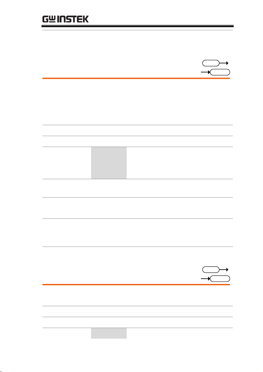
COMMAND OVERVIEW
Query example
:RES:SET?
>9.840
Return the resistance value (Ω ) of "Level = 100%".
:RESistance:LEVel
Set
Query
Description
Sets and queries for the “Level” % (percentage of
the Set conductance value) of the CR dynamic
mode.
This command applies in “Dyna.Level” is
“Percent”.
Syntax
:RESistance:LEVel {<NRf> | MINimum | MAXimum }
Query Syntax
:RESistance:LEVel?
Parameter
<NRf>
% of "Set" value level (unit is %)
MINimum
Minimum % of "Set" conductance level
MAXimum
Maximum % of "Set" conductance level
Return parameter
Return the Millisiemens of "% Level", by the "<NR2>"
string.
Example
:RES:LEV MIN
Sets the % level Millisiemens value to the minimum.
Query example
:RES:LEV?
>50
Return the Millisiemens of "50% Level".
Related
Commands
:RESistance:SET
:RESistance:RISE
Set
Query
Description
Sets and queries for the rising current slew rate of
the CR dynamic mode.
Syntax
:RESistance:RISE {<NRf> | MINimum | MAXimum }
Query Syntax
:RESistance:RISE?
Parameter
<NRf>
Rising current slew rate(unit is [mA/us])
95
Page 98

PEL-3000(H) Programming Manual
MINimum
Minimum slew rate
MAXimum
Maximum slew rate
Return parameter
Return the rise of the slew rate, by the "<NR2>"
string.
Example
:RES:RISE MIN
Sets the rising slew rate to the minimum.
Query example
:RES:RISE?
>50.000
Return the rise of the slew rate.
Related
Commands
:RESistance:FALL
:RESistance:FALL
Set
Query
Description
Sets and queries for the falling current slew rate of
the CR dynamic mode.
Syntax
:RESistance:FALL {<NRf> | MINimum | MAXimum }
Query Syntax
:RESistance:FALL?
Parameter
<NRf>
Falling slew rate (unit is [mA/us])
MINimum
Minimum slew rate
MAXimum
Maximum slew rate
Return parameter
Return the falling of the conductance slew rate, by the
"<NR2>" string.
Example
:RES:FALL MIN
Sets the falling slew rate to the minimum.
Query example
:RES:FALL?
>50.000
Return the falling of the slew rate.
Related
Commands
:RESistance:RISE
96
Page 99

COMMAND OVERVIEW
:RESistance:T1
Set
Query
Description
Sets and queries for the “Timer1” time of CR
dynamic mode.
This command applies in “Dyna.Time” is
“T1/T2”.
Syntax
:RESistance:T1 {<NRf>[s] | MINimum | MAXimum }
Query Syntax
:RESistance:T1?
Parameter
<NRf>[s]
T1 timer setting. (unit is seconds)
MINimum
Minimum time
MAXimum
Maximum time
Return parameter
Return the setting of the timer T1, by the "<NR2>"
string.
Example
:RES:T1 0.2
Sets the setting of the timer T1.
Query example
: RES:T1?
>0.2
Return the setting of the timer T1.
Related
Commands
:RESistance:T2
:RESistance:T2
Set
Query
Description
Sets and queries for the “Timer2” time of CR
dynamic mode.
This command applies in “Dyna.Time” is
“T1/T2”.
Syntax
:RESistance:T2 {<NRf>[s] | MINimum | MAXimum }
Query Syntax
:RESistance:T2?
Parameter
<NRf>[s]
T2 timer setting. (unit is seconds)
MINimum
Minimum time
97
Page 100

PEL-3000(H) Programming Manual
MAXimum
Maximum time
Return parameter
Return the setting of the timer T2, by the "<NR2>"
string.
Example
:RES:T2 0.2
Sets the setting of the timer T2.
Query example
:RES:T2?
>0.2
Return the setting of the timer T2.
Related
Commands
:RESistance:T1
:RESistance:FREQuency
Set
Query
Description
Sets and queries for “Frequency” value of the CR
dynamic mode.
This command applies in “Dyna.Time” is
“Freq/Duty”.
Syntax
:RESistance:FREQuency {<NRf> | MINimum |
MAXimum }
Query Syntax
:RESistance:FREQuency?
Parameter
<NRf>
Sets the switching frequency.
(unit is hertz)
MINimum
Minimum frequency
MAXimum
Maximum frequency
Return parameter
Return the switching frequency, by the "<NR2>"
string.
Example
:RES:FREQ 60
Sets frequency to 60Hz.
Query example
:RES:FREQ?
>60
Returns the switching frequency as 60Hz.
Related
Commands
:RESistance:DUTY
98
 Loading...