

Page 1

Electrical Safety Tester
GPT-9000 Series
USER MANUAL
GW INSTEK PART NO. 82PT-90000EA1
ISO-9001 CERTIFIED MANUFACTURER
99 Washington Street
Melrose, MA 02176
Phone 781-665-1400
Toll Free 1-800-517-8431
Visit us at www.TestEquipmentDepot.com
Page 2

This manual contains proprietary information, which is protected by
copyright. All rights are reserved. No part of this manual may be
photocopied, reproduced or translated to another language without
prior written consent of Good Will company.
The information in this manual was correct at the time of printing.
However, Good Will continues to improve products and reserves the
rights to change specification, equipment, and maintenance
procedures at any time without notice.
Good Will Instrument Co., Ltd.
No. 7-1, Jhongsing Rd., Tucheng Dist., New Taipei City 236, Taiwan.
Page 3

SAFETY INSTRUCTIONS
Table of Contents
SAFETY INSTRUCTIONS .................................................. 5
GETTING STARTED .......................................................... 9
GPT-9000 Series Overview ................... 10
Appearance .......................................... 14
Set Up .................................................. 22
OPERATION .................................................................. 29
Menu Tree ............................................ 31
Test Lead Connection ........................... 35
ACW, DCW and GB Manual Testing ...... 37
Special MANU Test Mode (000) ........... 74
Automatic Tests ................................... 79
Common Utility Settings ...................... 96
EXTERNAL CONTROL ................................................... 103
External Control Overview .................. 104
REMOTE CONTROL ...................................................... 110
Interface Configuration ...................... 111
Command Syntax ............................... 115
Command List ................................... 118
Error Messages .................................. 154
FAQ .............................................................................. 155
APPENDIX .................................................................... 157
Fuse Replacement .............................. 157
Error Messages .................................. 158
GPT-9000 Specifications .................... 161
GPT-9800 Dimensions ....................... 167
3
Page 4

GPT-9000 Series User Manual
GPT-9900 Dimensions ....................... 168
Declaration of Conformity .................. 169
INDEX .......................................................................... 170
4
Page 5

SAFETY INSTRUCTIONS
WARNING
Warning: Identifies conditions or practices that
could result in injury or loss of life.
CAUTION
Caution: Identifies conditions or practices that
could result in damage to the GPT-9000 or to other
properties.
DANGER High Voltage
Attention Refer to the Manual
Protective Conductor Terminal
Frame or Chassis Terminal
Earth (ground) Terminal
SAFETY INSTRUCTIONS
This chapter contains important safety
instructions that you must follow during
operation and storage. Read the following before
any operation to ensure your safety and to keep
the instrument in the best possible condition.
Safety Symbols
These safety symbols may appear in this manual or on the
instrument.
5
Page 6

GPT-9000 Series User Manual
Do not dispose electronic equipment as unsorted
municipal waste. Please use a separate collection
facility or contact the supplier from which this
instrument was purchased.
General
Guideline
CAUTION
Do not place any heavy object on the GPT-9000.
Avoid severe impact or rough handling that
leads to damaging the GPT-9000.
Do not discharge static electricity to the GPT-
9000.
Use only mating connectors, not bare wires, for
the terminals.
Do not block the cooling fan opening.
Do not disassemble the GPT-9000 unless you are
qualified.
(Measurement categories) EN 61010-1:2010 specifies the
measurement categories and their requirements as follows. The
GPT-9000 does not fall under category II, III or IV.
Measurement category IV is for measurement performed at the
source of low-voltage installation.
Measurement category III is for measurement performed in the
building installation.
Measurement category II is for measurement performed on the
circuits directly connected to the low voltage installation.
Power Supply
WARNING
AC Input voltage range:
100/120/220/230VAC ±10%
Frequency: 50Hz/60Hz
To avoid electrical shock connect the protective
grounding conductor of the AC power cord to
an earth ground.
Safety Guidelines
6
Page 7

SAFETY INSTRUCTIONS
Cleaning the
GPT-9000
Disconnect the power cord before cleaning.
Use a soft cloth dampened in a solution of mild
detergent and water. Do not spray any liquid.
Do not use chemicals containing harsh material
such as benzene, toluene, xylene, and acetone.
Operation
Environment
Location: Indoor, no direct sunlight, dust free,
almost non-conductive pollution (Note below)
Relative Humidity: ≤ 70% (no condensation)
Altitude: < 2000m
Temperature: 0˚C~40˚C
(Pollution Degree) EN 61010-1:2010 specifies the pollution degrees
and their requirements as follows. The GPT-9000 falls under degree
2.
Pollution refers to “addition of foreign matter, solid, liquid, or
gaseous (ionized gases), that may produce a reduction of dielectric
strength or surface resistivity”.
Pollution degree 1: No pollution or only dry, non-conductive
pollution occurs. The pollution has no influence.
Pollution degree 2: Normally only non-conductive pollution
occurs. Occasionally, however, a temporary conductivity caused
by condensation must be expected.
Pollution degree 3: Conductive pollution occurs, or dry, non-
conductive pollution occurs which becomes conductive due to
condensation which is expected. In such conditions, equipment
is normally protected against exposure to direct sunlight,
precipitation, and full wind pressure, but neither temperature
nor humidity is controlled.
Storage
environment
Location: Indoor
Temperature: -10°C to 70°C
Relative Humidity: ≤ 85% (no condensation)
Disposal
Do not dispose this instrument as unsorted
municipal waste. Please use a separate collection
facility or contact the supplier from which this
instrument was purchased. Please make sure
discarded electrical waste is properly recycled to
reduce environmental impact.
7
Page 8

GPT-9000 Series User Manual
Green/ Yellow:
Earth
Blue:
Neutral
Brown:
Live (Phase)
Power cord for the United Kingdom
When using the safety tester in the United Kingdom, make sure the
power cord meets the following safety instructions.
NOTE: This lead/appliance must only be wired by competent persons
WARNING: THIS APPLIANCE MUST BE EARTHED
IMPORTANT: The wires in this lead are coloured in accordance with the
following code:
As the colours of the wires in main leads may not correspond with
the coloured marking identified in your plug/appliance, proceed
as follows:
The wire which is coloured Green & Yellow must be connected to
the Earth terminal marked with either the letter E, the earth symbol
or coloured Green/Green & Yellow.
The wire which is coloured Blue must be connected to the terminal
which is marked with the letter N or coloured Blue or Black.
The wire which is coloured Brown must be connected to the
terminal marked with the letter L or P or coloured Brown or Red.
If in doubt, consult the instructions provided with the equipment
or contact the supplier.
This cable/appliance should be protected by a suitably rated and
approved HBC mains fuse: refer to the rating information on the
equipment and/or user instructions for details. As a guide, a cable
of 0.75mm2 should be protected by a 3A or 5A fuse. Larger
conductors would normally require 13A types, depending on the
connection method used.
Any exposed wiring from a cable, plug or connection that is
engaged in a live socket is extremely hazardous. If a cable or plug is
deemed hazardous, turn off the mains power and remove the cable,
any fuses and fuse assemblies. All hazardous wiring must be
immediately destroyed and replaced in accordance to the above
standard.
8
Page 9

GETTING STARTED
POWER
START STOP
REMOTE
MANU/AUTO EDIT/SAVE UTILITY
ESC PAGE
GPT-9803
Tester
HIGH VOLTAGE
CAUTION
5.0 kVAC MAX.
6.0 kVDC MAX.
AC / DC Withstanding Voltage /
Insulation Resistance
RETURN
PASS FAIL READY TEST
GPT-9000 Series Overview .............................................. 10
Series lineup .................................................................................................. 10
Model Overview ........................................................................................... 11
Main Features ................................................................................................ 11
Accessories ..................................................................................................... 12
Package Contents ......................................................................................... 13
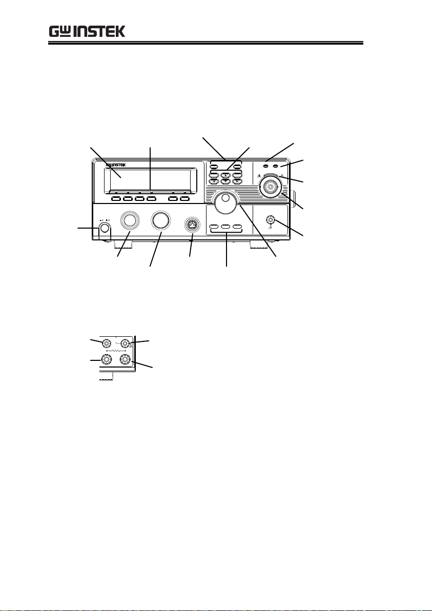
Appearance .................................................................... 14
GPT-9801/9802/9803/9903 Front Panel ................................................. 14
GPT-9804/9904 Front Panel ....................................................................... 14
GPT-9801/9802/9803/9804 Rear Panels ................................................. 18
GPT-9903 Rear Panel ................................................................................... 18
GPT-9904 Rear Panel ................................................................................... 19
Set Up ........................................................................... 22
Line Voltage Connection and Power Up ................................................. 22
Installing the Optional GPIB Card ............................................................ 24
Workplace Precautions ............................................................................... 25
Operating Precautions ................................................................................. 26
Basic Safety Checks ...................................................................................... 28
GETTING STARTED
This chapter describes the safety tester in a
nutshell, including its main features and front /
rear panel introduction. After going through the
overview, please read the safety considerations in
the Set Up chapter.
9
Page 10

GPT-9000 Series User Manual
GPT-9000 Series Overview
Series lineup
The GPT-9000 Series Safety Testers are AC/DC withstanding
voltage, insulation resistance and ground bond safety testers. The
GPT-9801 is an AC withstanding voltage tester, the GPT-9802 is an
AC/DC withstanding voltage tester and the GPT-9803 & GPT-9903
are AC/DC withstanding voltage and insulation resistance testers.
The GPT-9804 & GPT-9904 include all the test functions of the other
models as well as ground bond testing. All models can operate at
up to 5kVAC for AC withstanding voltage testing and at up to
6kVDC for DC withstanding voltage testing (excluding the GPT-
9801).
For the GPT-99XX models, the testing terminals are also mirrored
on the rear panel for added safety and for more permanent safety
testing environments.
The GPT-9903 and 9904 also add an innovative a sweep function to
view test results as a graph.
The GPT-9000 Series can store up to 100 manual tests, as well as
run up to 16 manual tests sequentially as an automatic test,
allowing the safety testers to accommodate any number of safety
standards, including IEC, EN, UL, CSA, GB, JIS and others.
Note: Throughout this user manual, the terms ACW, DCW, IR and
GB refer to AC Withstanding, DC Withstanding, Insulation
Resistance and Ground Bond testing, respectively.
10
Page 11

GETTING STARTED
Model name
ACW
DCW
IR
GB
Sweep
GPT-9801
GPT-9802
GPT-9803
GPT-9804
GPT-9903
GPT-9904
Performance
ACW: 5kVAC
DCW: 6kVDC
IR: 50V~1000V (50V steps)
GB: 3A~30A (GPT-98XX); 3A~32A (GPT-99XX)
Features
Ramp up time control
Safety discharge
100 test conditions (MANU mode)
100 automatic tests (AUTO mode)
Over temperature, voltage and current
protection
Pass, Fail, Test, High Voltage and Ready
indicators
PWM output (90% efficiency, increased
reliability)
Interlock (configurable).
Sweep Function.
Model Overview
Main Features
11
Page 12

Interface
Remote control start/stop interface terminal
RS232/USB interface for programming
Optional GPIB interface for programming
Signal I/O port for pass/fail/test monitoring
and start/stop control/interlock
Accessories
Standard
Accessories
Part number
Description
GHT-114 x1
Test lead
Region dependent
Power cord
GTL-115 x1
GB Test leads
(GPT-9804/9904 only)
N/A
Remote terminal male plug
N/A
Interlock key
Optional
Accessories
Part number
Description
GHT-205
High Voltage Test Probe
GHT-113
High Voltage Test Pistol
GTL-232
RS232C cable
GTL-248
GPIB cable
GTL-247
USB cable
GRA-402
Rack Adapter Panel
(19”, 4U)
(GPT-9801/9802/9803/
9804 only)
Options
Part number
Description
Opt.01 GPIB Interface
GPIB module
GPT-9000 Series User Manual
12
Page 13

GETTING STARTED
Opening the box
Contents
(single unit)
GPT-9000 unit
Quick Start guide
User manual CD
CTC (Calibration
Traceable Certificate)
Power cord x1 (region
dependent)
GHT-114 test leads x1
GTL-115 test leads x1
(GPT-9804/9904)
Remote terminal male
plug
Interlock key
Note
Keep the packaging, including the box, polystyrene
foam and plastic envelopes should the need arise
to return the unit to GW Instek.
Package Contents
Check the contents before using the GPT-9000.
13
Page 14
GPT-9000 Series User Manual
POWER
START STOP
REMOTE
MANU/AUTO EDIT/SAVE UTILITY
ESC PAGE
GPT-9803
Tester
HIGH VOLTAGE
CAUTION
5.0 kVAC MAX.
6.0 kVDC MAX.
AC / DC Withstanding Voltage /
Insulation Resistance
RETURN
PASS FAIL READY TEST
PASS/FAIL indicators
Directional keysFunction keys
HIGH VOLTAGE
indicator
RETURN
terminal
REMOTE terminal
STOP button
START button
POWER
button
Display
Scroll wheel
Configuration keys
READY indicator
TEST indicator
HIGH VOLTAGE
output terminal
HIGH VOLTAGE
CAUTION
5.0 kVAC MAX.
6.0 kVDC MAX.
GB Rx
SENSE H
SOURCE H
SENSE L
SOURCE L
RETURN
HI-POT
IR
SOURCE L
SENSE L &
RETURN Terminal
SENSE H
SOURCE H
Appearance
GPT-9801/9802/9803/9903 Front Panel
GPT-9804/9904 Front Panel
14
Page 15

GETTING STARTED
Display
240 X 64 dot matrix display (LCD)
Function keys
The function keys correspond to the soft-keys
directly above on the main display.
Pass/Fail
indicators
PASS
FAIL
The PASS and FAIL indicators
light up upon a PASS or FAIL test
result at the end of a manual test
or automatic test.
ESC key
ESC
The ESC key is used to exit out of
a menu or cancel a setting.
PAGE key
PAGE
The PAGE key is used to view
automatic test information and
test results.
Directional arrow
keys
The directional arrow keys are
used to navigate menus and
parameter settings.
READY indicator
READY
The READY indicator is lit when
the tester is ready to begin testing.
The STOP button is used to put
the tester into READY status.
TEST indicator
TEST
The TEST indicator is lit when a
test is on. The START button is
used to put the tester into TEST
status.
HIGH VOLTAGE
indicator
HIGH VOLTAGE
CAUTION
5.0 kVAC MAX.
6.0 kVDC MAX.
The HIGH VOLTAGE indicator
will light up when an output
terminal is active. Only after the
test has finished or stopped will
the indicator turn off.
15
Page 16

GPT-9000 Series User Manual
HIGH VOLTAGE
output terminal
HIGH VOLTAGE
CAUTION
5.0 kVAC MAX.
6.0 kVDC MAX.
The HIGH VOLTAGE terminal
output is used for outputting the
testing voltage. The terminal is
recessed for safety. This terminal
is used in conjunction with the
RETURN terminal.
WARNING
USE EXTREME CAUTION.
Do not touch the HIGH VOLTAGE terminal
during testing.
RETURN terminal
GPT-9801/9802
/9803/9903
RETURN
The RETURN terminal is
used for IR, DCW and ACW
tests.
RETURN, SENSE
and SOURCE
terminals
GPT-9804/9904
SOURCE H
SENSE H
SOURCE L
SENSE L
GB Rx
RETURN
HI-POT
IR
The RETURN terminal is
used for IR, DCW and ACW
tests.
The SOURCE H, SOURCE L,
SENSE H and SENSE L
terminals are used for GB
tests.
Scroll wheel
The scroll wheel is used to edit
parameter values.
UTILITY key
UTILITY
Used to enter the MANU Utility or
Common Utility menu.
16
Page 17

GETTING STARTED
EDIT/SAVE key
EDIT/SAVE
Used to start editing
MANU/AUTO tests as well as
save settings and parameters.
MANU/AUTO
key
MANU/AUTO
The MANU/AUTO key is used to
select manual tests (MANU) or
automatic tests (AUTO).
REMOTE
terminal
REMOTE
The REMOTE terminal is used to
connect to a remote controller.
STOP button
STOP
The STOP button is used to
stop/cancel tests. The STOP
button will also put the safety
tester in the READY status to
begin testing.
START button
START
The START button is used to start
tests.
The START button can be used to
start tests when the tester is in the
READY status. Pressing the
START button will put the tester
in the TEST status.
POWER switch
POWER
Turns the power on. The safety
tester will always start up with the
last test setting from when the
instrument was last powered
down.
17
Page 18

GPT-9000 Series User Manual
SIGNAL I/O USB A port RS232 port Fan
Fuse selectorLine voltage
Optional GPIB port
GND
TO AVOID ELECTRIC SHOCK THE POWER CORD
PROTECTIVE GROUNDING CONDUCTOR MUST BE
ONLY WITH SPECIFIED TYPE AND RATED FUSE
.
NO OPERATOR SERVICEABLE COMPONENTS INSIDE
.
DO NOT REMOVE COVERS REFER SERVICING TO
FOR CONTINUED FIRE PROTECTION
.
REPLACE
CONNECTED TO GROUND
.
QUALIFIED PERSONNEL.
WARNING
AC
LINE VOLTAGE
100V
230V
220V
120V
SELECTION
207~250V
RANGE
90~110V
198~242V
108~132V
(50/60 Hz)
T 5A
250V
FUSE
POWER MAX.
500VA
GND
SIGNAL I / O RS 232
SER. NO . LB
ENSURE THE POWER IS REMOVED FROM
THE INSTRUMENT BEFORE REPLACING THE FUSE
GPIB
T 2.5A
250V
TO AVOID ELECTRIC SHOCK THE POWER CORD
PROTECTIVE GROUNDING CONDUCTOR MUST BE
ONLY WITH SPECIFIED TYPE AND RATED FUSE.
NO OPERATOR SERVICEABLE COMPONENTS INSIDE.
DO NOT REMOVE COVERS. REFER SERVICING TO
FOR CONTINUED FIRE PROTECTION. REPLACE
CONNECTED TO GROUND.
QUALIFIED PERSONNEL.
WARNING
AC
LINE VOLTAGE
100V
230V
220V
120V
SELECTION
207~250V
RANGE
90~110V
198~242V
108~132V
(50/60Hz)
250V
250V
T 10A
FUSE
T 6.3A
MAX.
1000VA
GND
ENSURE THE POWER IS REMOVED FROM
THE INSTRUMENT BEFORE REPLACING THE FUSE
POWER
SIGNAL I / O RS232
GPIB
HIGH VOLTAGE
CAUTION
MAX.
6.0 kVDC
5.0 kVAC
RETURN
SER. NO. LB
Signal I/O, RS232
& USB port
Fan vents
Fuse selectorLine voltage
Optional GPIB port
High voltage terminal
GND
Return
terminal
GPT-9801/9802/9803/9804 Rear Panels
GPT-9903 Rear Panel
18
Page 19

GETTING STARTED
TO AVOID ELECTRIC SHOCK THE POWER CORD
PROTECTIVE GROUNDING CONDUCTOR MUST BE
ONLY WITH SPECIFIED TYPE AND RATED FUSE.
NO OPERATOR SERVICEABLE COMPONENTS INSIDE.
DO NOT REMOVE COVERS. REFER SERVICING TO
FOR CONTINUED FIRE PROTECTION. REPLACE
CONNECTED TO GROUND.
QUALIFIED PERSONNEL.
WARNING
AC
LINE VOLTAGE
100V
230V
220V
120V
SELECTION
207~250V
RANGE
90~110V
198~242V
108~132V
(50/60Hz)
250V
250V
T 10A
FUSE
T 6.3A
MAX.
1000VA
GND
ENSURE THE POWER IS REMOVED FROM
THE INSTRUMENT BEFORE REPLACING THE FUSE
POWER
SIGNAL I / O RS232
GPIB
GB Rx
SENSE H
SOURCE H
SENSE L
SOURCE L
RETURN
HI-POT
IR
HIGH VOLTAGE
CAUTION
MAX.
6.0 kVDC
5.0 kVAC
SER. NO. LB
High voltage terminal
Signal I/O, RS232
& USB port
Fan vents
Fuse selectorLine voltage
Optional GPIB port
GND
Return, Sense
and Source
terminals
SIGNAL I/O port
SIGNAL I / O
The SIGNAL I/O port is used to
monitor the tester status (PASS,
FAIL, TEST) and input (START/
STOP signals). It is also used with
the Interlock key.
USB A port
Used for remote control.
RS232 interface
port
RS232
Used for remote control and
firmware updates.
Fan/Fan Vents
Exhaust fan. Allow enough room
for the fan to vent. Do not block the
fan openings.
GND
GND
Connect the GND (ground)
terminal to the earth ground.
GPT-9904 Rear Panel
19
Page 20

GPT-9000 Series User Manual
Line voltage input
220
230
100
120
Line voltage input:
100/120/220/230VAC ±10%
Line voltage fuse
220
230
100
120
Line voltage selector and fuse:
GPT-98XX:
100V/120V
T5A 250V
220V/230V
T2.5A 250V
GPT-99XX:
100V/120V
T10A 250V
220V/230V
T6.3A 250V
Optional GPIB
port
GPIB
Optional GPIB interface for remote
control.
HIGH VOLTAGE
output terminal
GPT-9903/9904
CAUTION
HIGH VOLTAGE
MAX.
5.0 kVAC
6.0 kVDC
The HIGH VOLTAGE
terminal output is used for
outputting the testing
voltage.
WARNING
USE EXTREME CAUTION.
Do not touch the HIGH VOLTAGE terminal
during testing.
RETURN terminal
GPT-9903
RETURN
The RETURN terminal is
used for IR, DCW and ACW
tests.
20
Page 21

GETTING STARTED
RETURN/
SENSE and
SOURCE
terminals
GPT-9904
GB Rx
SENSE H
SOURCE H
SENSE L
SOURCE L
RETURN
HI-POT
IR
The RETURN terminal is
used for IR, DCW and ACW
tests.
The SOURCE L/H AND
SENSE L/H terminals are for
GB tests only.
21
Page 22

GPT-9000 Series User Manual
Background
Before powering up the GPT-9000 ensure the
correct voltage has been selected on the rear
panel. The GPT-9000 supports line voltages of
100V/120V/220V and 230V.
Steps
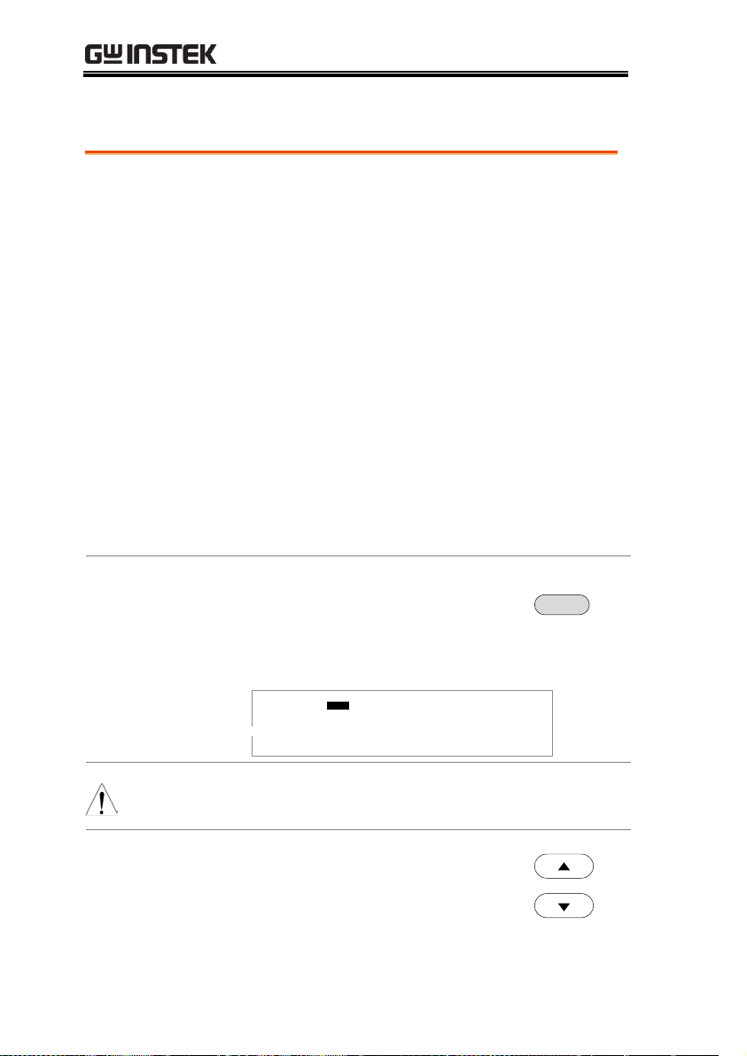
1. Check the line voltage and the fuse
in the fuse holder.
Page 157
The desired line voltage
should line up with the
arrow on the fuse holder.
2
2
0
1
0
0
120
230
2. Connect the power cord to
the AC voltage input.
2
2
0
1
0
0
120
230
3. If the power cord does not
have an earth ground,
ensure the ground
terminal is connected to an
earth ground.
GND
Warning
Ensure the power cord is connected to an earth
ground. Failure could be harmful to the operator
and instrument.
4. Press the Power button.
POWER
Set Up
Line Voltage Connection and Power Up
22
Page 23

GETTING STARTED
5. When the unit is powering up, all the LED
indicators will light. Check to make sure all 5
LED indicators are working.
6. Check to make sure the System Self Test passes
without errors.
S y s e m t
H a r w a rd
e C
h
C h e c i g . .n .
F i r w a rm
e C h
SYS T E S M E L F T E S T
k
e c i g . .n .k
e c i g . .n .k
After the System Self Test completes, the tester will
go into VIEW status and be ready to operate.
I R G B A CW D CW
E
F R E Q = 0 H z 6
0
100
k V
EIV
MT I E = 0 0 1 . 0 SR
0 0 m AER F =# 0 .0
1 . 0 0 m AIH ES = 0T
0 0 . 1 S0AM P =R
W
VIEW status
MM A UN N A_2M A NU = * * * - 0 0
m A
WARNING
See the Appendix on page 158 for details if a selftest error is detected.
23
Page 24

GPT-9000 Series User Manual
Background
The optional GPIB is a user-installable option.
Follow the instructions below to install the
GPIB card.
WARNING
Before installing the optional GPIB card ensure the
GPT-9000 turned is off and disconnected from
power.
Steps
1. Remove the screws from the rear panel cover
plate.
2. Insert the GPIB card into the two slots on either
side of the opening. Push the card gently until it
is fully inserted.
Installing the Optional GPIB Card
24
Page 25

GETTING STARTED
Background
The GPT-9000 is a high voltage instrument that
outputs dangerous voltages. The following
section describes precautions and procedures
that must be followed to ensure a safe work
environment.
WARNING
The GPT-9000 generates voltages in excess of
5kVAC or 6kVDC. Follow all safety precautions,
warnings and directions given in the following
section when using the GPT-9000.
1. Only technically qualified personnel should be
allowed to operate the safety tester.
2. The operating workplace must be fully isolated,
especially when the instrument is in operation.
The instrument should be clearly labeled with
appropriate warning signage.
3. The operator should not wear any conductive
materials, jewelry, badges, or other items, such
wrist watches.
4. The operator should wear insulation gloves for
high voltage protection.
5. Ensure the earth ground of the line voltage is
properly grounded.
6. Ensure any devices that are adversely affected
by magnetic fields are not placed near the
tester.
Workplace Precautions
25
Page 26

GPT-9000 Series User Manual
Background
The GPT-9000 is a high voltage instrument that
outputs dangerous voltages. The following
section describes precautions and procedures
that must be followed to ensure that the tester
is operated in a safe manner.
WARNING
The GPT-9000 generates voltages of up to 5kVAC
or 6kVDC. Follow all safety precautions, warnings
and directions given in the following section when
using the GPT-9000.
1. Never touch the safety tester, lead wires,
terminals, probes and other connected
equipment when the tester is testing.
2. Do not turn the safety tester on and off quickly
or repeatedly. When turning the power off,
please allow a few moments before turning the
power back on. This will allow the protection
circuits to properly initialize.
Do not turn the power off when a test is
running, unless in an emergency.
3. Only use those test leads supplied with the
instrument. Leads with inappropriate gauges
can be dangerous to both the operator and the
instrument.
For GB testing, never use the Sense leads on the
SOURCE terminals.
4. Do not short the HIGH VOLTAGE terminal
with ground. Doing so could charge the chassis
to dangerously high voltages.
Operating Precautions
26
Page 27

GETTING STARTED
5. Ensure the earth ground of the line voltage is
properly grounded.
6. Only connect the test leads to the HIGH
VOLTAGE/SOURCE H/SENSE H terminals
before the start of a test. Keep the test leads
disconnected at all other times.
7. Always press the STOP button when pausing
testing.
8. Do not leave the safety tester unattended.
Always turn the power off when leaving the
testing area.
9. When remotely controlling the safety tester,
ensure adequate safety measures are in place to
prevent:
Inadvertent output of the test voltage.
Accidental contact with the instrument during
testing. Ensure that the instrument and DUT are
fully isolated when the instrument is remotely
controlled.
10. Ensure an adequate discharge time for the
DUT.
When DCW or IR tests are performed, the DUT,
test leads and probes become highly charged.
The GPT-9000 has discharge circuitry to
discharge the DUT after each test. The time
required for a DUT to discharge depends on the
DUT and test voltage.
Never disconnect the safety tester before a
discharge is completed.
27
Page 28
GPT-9000 Series User Manual
Background
The GPT-9000 is a high voltage device and as
such, daily safety checks should be made to
ensure safe operation.
1. Ensure all test leads are not broken and are free
from defects such as cracks or splitting.
2. Ensure the safety tester is always connected to
an earth ground.
3. Test the safety tester operation with a low
voltage/current output:
Ensure the safety tester generates a FAIL
judgment when the HIGH VOLTAGE and
RETURN terminals are shorted (using the
lowest voltage/current as the testing
parameters).
WARNING
Do not use high voltages/currents when the HIGH
VOLTAGE and RETURN terminals are shorted. It
may result in damage to the instrument.
Basic Safety Checks
28
Page 29

OPERATION
Menu Tree...................................................................... 31
Menu Tree Overview ................................................................................... 32
Test Lead Connection ..................................................... 35
ACW, DCW, IR Connection ....................................................................... 35
GB Connection .............................................................................................. 36
ACW, DCW and GB Manual Testing ................................. 37
Choose/Recall a Manual Test Number ................................................... 38
Edit Manual Test Settings ........................................................................... 39
Setting the Test Function ............................................................................ 40
Setting the Test Voltage or Test Current ................................................. 40
Setting the Test Frequency ......................................................................... 41
Setting the Upper and Lower Limits ........................................................ 42
Setting a Reference Value ........................................................................... 44
Setting the Test Time (Timer) .................................................................... 46
Setting the Ramp Up Time ......................................................................... 48
Creating a MANU Test File Name ........................................................... 49
Setting the ARC Mode ................................................................................. 50
Setting PASS HOLD ..................................................................................... 53
Setting FAIL MODE ..................................................................................... 54
Setting MAX HOLD ..................................................................................... 55
Setting the Grounding Mode ..................................................................... 56
Saving and Exiting EDIT Status ................................................................ 61
Running a MANU Test ............................................................................... 62
PASS / FAIL MANU Test .......................................................................... 66
Zeroing of the Test Leads (GB only) ........................................................ 71
Special MANU Test Mode (000) ...................................... 74
Automatic Tests ............................................................. 79
OPERATION
29
Page 30

GPT-9000 Series User Manual
Choose/Recall an Automatic Test ........................................................... 79
Edit Automatic Test Settings ..................................................................... 81
Adding a Step to the Automatic Test ...................................................... 82
Creating an AUTO Test File Name .......................................................... 83
Saving and Exiting EDIT Status ............................................................... 84
Automatic Test Page View ........................................................................ 85
Running an Automatic Test ...................................................................... 88
Automatic Test Results ............................................................................... 92
30
Page 31

OPERATION
status
SET
T
PASS/FAIL result
status
OTS
P
status
YAER
D
status
EIV
W
status
IDE
T
Press
START
Press
STOP
Press
MANU/
AUTO
Save the MANU
test or AUTO test
Press
STOP
Press
STOP
Press
EDIT/
SAVE
Press
STOP
2
Common Utility
Settings
1
PAGE View
(AUTO mode
only)*
Press
PAGE
Press
ESC
Press
EDIT/
SAVE
Switch to AUTO
mode
MANU UTILITY
menu (MANU
mode only)
1
Press
UTILITY
1 Press EDIT/SAVE to save settings, or ESC to cancel and return to the previous screen.
2 Press the STOP key twice for a FAIL result.
3 When in MANU mode, selecting MANU number 000 will enter the special manual mode.
4 The Sweep mode function is only accessible in the special manual mode.
PAGE View
(AUTO mode
only)*
PAGE View
(AUTO mode
only)
1
Switch to MANU
mode
Special manual
mode
Press
UTILITY
Hold
MANU/
AUTO
MANU
no.
# 000
3
Menu Tree
This section describes the overall structure of the operation statuses
and modes for the GPT-9000 safety testers. The testers have two
main testing modes (MANU, AUTO) and 5 main operation statuses
(VIEW, EDIT, READY, TEST and STOP).
31
Page 32
GPT-9000 Series User Manual
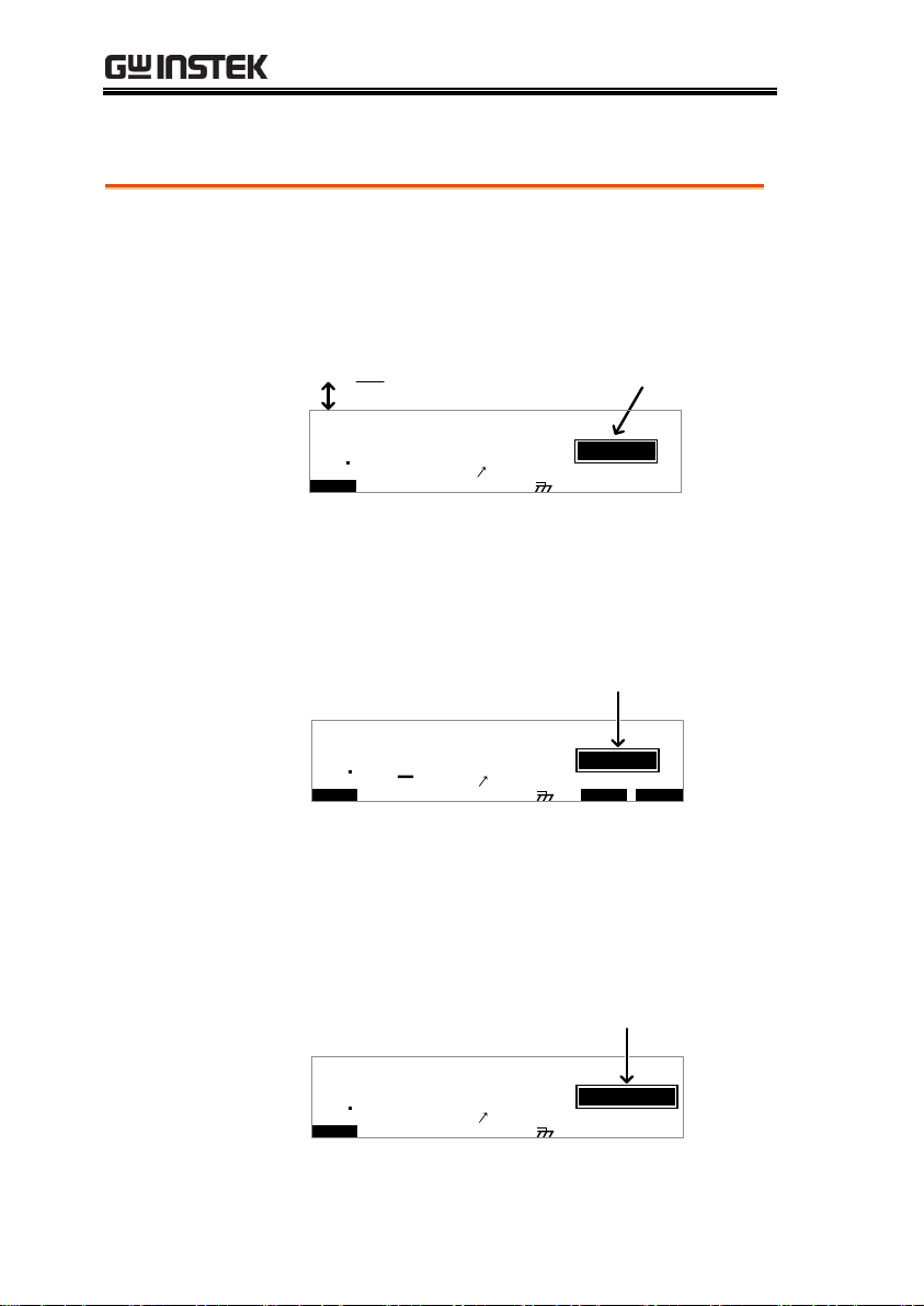
VIEW status
VIEW status is used to view the parameters of
the selected manual test/automatic test. The
VIEW status is also used to put the tester into
MANU or AUTO mode.
I R G B A CW D CW
E
F R E Q = 0 H z 6
0
100
k V
EIV
MT I E = 0 0 1 . 0 SR
0 0 m AER F =# 0 .0
1 . 0 0 m AIH ES = 0T
0 0 . 1 S0AM P =R
A U T O = 0 0 1 - 0 0 2
W
VIEW status
MM A UN N A_2M A NU = * * * - 0 0
MA U OT NA_
m A
E
EDIT status
EDIT status is used to edit the manual test or
automatic test parameters. Pressing the
EDIT/SAVE key will save any changes.
Pressing the ESC key will cancel any changes.
I R G B A CW D CW I / LH O I M ET R
E
F R EQ = 0 H z 6
0
100
k V
IDE
MT I E = 0 0 1 . 0 SR
0 0 m AER F =# 0 .0MMA UN N A_
1 . 0 0 m AIH ES = 0T
0 0 . 1 S0AM P =R
T2M A NU = * * * - 0 0
EDIT status
m A
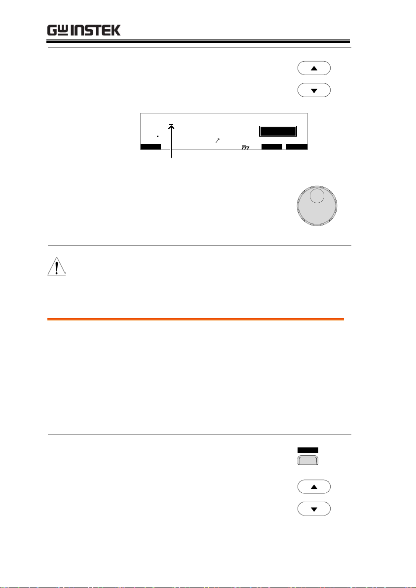
READY status
When the tester is in READY status, it is ready
to begin testing. Pressing the START button
will begin testing and put the tester into TEST
status. Pressing the MANU/AUTO key will
return the tester to VIEW status.
I R G B A CW D CW
E
F R EQ = 0 H z 6
0
100
k V
AER
MT I E = 0 0 1 . 0 SR
0 0 m AER F =# 0 .0
1 . 0 0 m AIH ES = 0T
0 0 . 1 S0AM P =R
D
MM A UN N A_2M A NU = * * * - 0 0
READY status
Y
m A
Menu Tree Overview
32
Page 33

OPERATION
TEST status
TEST status is active when a MANU test or
AUTO test is running. Pressing STOP will
cancel the MANU test or the remaining steps in
an AUTO test.
I R G B A CW D CW
E
F R E Q = 0 H z 6
0
100
k V
SET
MT I E = 0 0 1 . 0 SR
0 0 m AER F =# 0 .0
1 . 0 0 m AIH ES = 0T
0 0 . 1 S0AM P =R
MM A UN N A_2M A NU = * * * - 0 0
TEST status
T
m A
00 33
STOP status
STOP status is shown when a manual test or
automatic test did not finish running and has
been stopped by the operator. Pressing STOP
will return the tester to READY status.
I R G B A CW D CW
E
F R E Q = 0 H z 6
0
100
k V
OTS
MT I E = 0 0 1 . 0 SR
0 0 m AER F =# 0 .0
1 . 0 0 m AIH ES = 0T
0 0 . 1 S0AM P =R
MM A UN N A_2M A N U = * * * - 0 0
STOP status
P
m A
00 33
Page View
Up to 16 tests can be used to create an
automatic test. Page View is used to see which
manual tests (steps) an automatic test is
composed of. The steps can be re-arranged and
deleted in Page View.
O V EM W A PS K I PS D E L
E MA U OT N A_ 0A U T O = 0 0 1 - 0 1
M A NU _ N M E A VA C W= 0 . 0 0 k1
# 0 1 : 0 1 0 # 0 2 : 0 0 1 # 0 3 : 0 0 3 # 0 4 : 0 0 4
# 0 5 : 0 0 7 # 0 6 : 0 0 3 # 0 7 : 0 3 8 # 0 8 : 0 0 5
# 0 9 : # 1 0 : # 1 1 : # 1 2 :
# 1 3 : # 1 4 : # 1 5 : # 1 6 :
*
1 . 0 0 m AH I ES = 0T_
33
Page 34

GPT-9000 Series User Manual
AUTO mode
AUTO indicates that the tester is in AUTO
mode. AUTO mode is for creating/running a
sequence of up to 16 MANU tests.
I R G B A C W D CW A D D
E
F R E Q = 0 H z 6
0
100
k V
IDE
MT I E = 0 0 1 . 0 SR
0 0 m AER F =# 0 .0MA U OT N A_
1 . 0 0 m AIH ES = 0T
0 0 . 1 S0A MP =R
T2AU T O = 0 0 3 - 0 0
AUTO mode
m A
MANU mode
MANU mode is used to create and/or execute a
single test. MANU indicates that the manual
test mode is active.
I R G B A C W D CW I / LH O I M ET R
E
F R E Q = 0 H z 6
0
100
k V
IDE
MT I E = 0 0 1 . 0 SR
0 0 m AER F =# 0 .0MMA UN N A_
1 . 0 0 m AIH ES = 0T
0 0 . 1 S0A MP =R
T2M A N U = * * * - 0 0
MANU mode
m A
Common Utility
Settings
This utility controls the LCD, buzzer, interface
and control settings. These settings are system
wide.
K e y L o k : Oc
F F
S t a r t t r lC
D o u b l e A c t
i no
L C D B U Z Z N T EI R C T R L
:
: F R ON T P A N
MOC MO U N T I L I T Y
E L
FO F
I N T E R L C K :O
O FF
MANU Utility
Settings
The Manu Utility settings are configured for
each MANU test separately. The settings
include: ARC MODE, PASS HOLD, FAIL
MODE, MAX HOLD and GROUND MODE.
L I T Y IM A UN U T 2M A NU = * * * - 0 0
A R C M D E : OO FF
G RO U N D MO D E : NO
P A S S H L D :O O FF
F A I L M D E :O
PS T O
M A X H O L D : O F F
34
Page 35

OPERATION
Background
ACW, DCW and IR tests use the HIGH
VOLTAGE terminal and RETURN terminal
with the GHT-114 test leads.
ACW, DCW, IR Connection
High Voltage terminal
DUT
GPT-9000
Return terminal
Steps
1. Turn the power off on the safety tester.
2. Connect the high voltage test lead(red) to the
HIGH VOLTAGE terminal and screw firmly
into place.
3. Connect the return test lead(white) into the
RETURN terminal and screw the protector bar
into place, as shown below.
HIGH VOLTAGE
Terminal
RETURN
Terminal
Test Lead Connection
This section describes how to connect the GPT-9000 to a DUT for
withstanding, insulation resistance or ground bond testing.
ACW, DCW, IR Connection
35
Page 36

GB Connection
Background
GB tests use the SENSE H/L and SOURCE H/L
terminals with the GTL-115 test leads.
GB Connection
Source H
DUT
GPT-9000
Sense L
Sense H
Source L
Steps
1. Turn the power off on the safety tester.
2. Connect the Sense H lead to the SENSE H
terminal.
3. Connect the Sense L lead to the SENSE L
terminal.
4. Connect the Source H lead to the SOURCE H
terminal.
5. Connect the Source L lead to the SOURCE L
terminal.
SOURCE H
SENSE H
SOURCE L
SENSE L
GB Rx
RETURN
HI-POT
IR
Sense H lead Sense L lead
Source L leadSource H lead
GPT-9000 Series User Manual
36
Page 37

OPERATION
ACW, DCW and GB Manual Testing
This section describes how to create, edit and run a single ACW,
DCW, IR or GB safety test. Each Manual setting described in this
chapter only applies to the selected manual test – no other manual tests
are affected.
Each manual test can be stored/recalled to/from one of 100
memory locations. Each stored manual test can be used as a test
step when creating an AUTO test (page 79).
Choose/Recall a Manual Test number → from page 38.
Edit Manual Test Settings → from page 39.
Setting the Test Function→ from page 40.
Setting the Test Voltage or Test Current→ from page 40.
Setting the Test Frequency → from page 41.
Setting the Upper and Lower Limits → from page 42.
Setting a Reference Value → from page 44.
Setting the Test Time (Timer) → from page 46.
Setting the Ramp Up Time → from page 48.
Creating a MANU Test File Name→ from page 49.
Setting the ARC Mode → from page 50.
Setting PASS HOLD→ from page 53.
Setting FAIL MODE→ from page 54.
Setting MAX HOLD→ from page 55.
Setting the Grounding Mode → from page 56.
Saving and Exiting EDIT Status→ from page 61.
Running a MANU Test → from page 62.
PASS / FAIL MANU Test → from page 66.
Zeroing of the Test Leads (GB only) → from page 71
Special MANU Test Mode (000) → from page 74
Before operating the GPT-9000 please read the safety precautions as
outlined in the Set Up chapter on page 22.
37
Page 38

GPT-9000 Series User Manual
Background
ACW, DCW, IR and GB tests can only be
created in the MANU (manual) mode. MANU
number 001 to 100 can be saved and thus be
loaded when editing/creating a MANU test or
AUTO test. MANU number 000 is a special
mode. See page 71 for details on the special
mode.
Steps
1. If the tester is in AUTO mode,
press and hold the MANU/AUTO
key for three seconds to switch to
MANU mode.
The tester can only switch between
AUTO and MANU mode when in
the VIEW status.
MANU/AUTO
I R G B A CW D CW
E
F R E Q = 0 H z 6
0
100
k V
EIV
MT I E = 0 0 1 . 0 SR
0 0 m AER F =# 0 .0
1 . 0 0 m AIH ES = 0T
0 0 . 1 S0AM P =R
A U T O = 0 0 1 - 0 0 2
W
VIEW status
MM A UN N A_2M A N U = * * * - 0 0
MA U OT N A_
m A
E
2. Use the scroll wheel to choose the
MANU number.
MANU #
001~100
(MANU# 000 is a special mode)
I R G B A CW D CW
E
F R E Q = 0 H z 6
0
100
k V
EIV
MT I E = 0 0 1 . 0 SR
0 0 m AER F =# 0 .0MM A UN N A_
1 . 0 0 m AIH ES = 0T
0 0 . 1 S0AM P =R
W2M A NU = * * * - 0 0
MANU number
m A
Choose/Recall a Manual Test Number
38
Page 39

OPERATION
Note
The MANU number can only be chosen in VIEW
status. If in the EDIT status, switch to the VIEW
status by pressing the EDIT/SAVE or ESC key.
Background
To edit any of the manual test settings, the
tester must be in EDIT status.
Any settings or parameters that are edited only
apply to the currently selected MANU number.
Steps
1. Press the EDIT/SAVE key when in
VIEW status to enter the EDIT
status. This will enter the EDIT
status for the chosen test number.
EDIT/SAVE
I R G B A CW D CW I / LH O I M ET R
E
F R E Q = 0 H z 6
0
100
k V
IDE
MT I E = 0 0 1 . 0 SR
0 0 m AER F =# 0 .0MM A UN N A_
1 . 0 0 m AIH ES = 0T
0 0 . 1 S0AM P =R
T2M A NU = * * * - 0 0
EIV
W
m A
2. The Status changes from VIEW to EDIT.
Note
Pressing the EDIT/SAVE key again will save the
settings for the current test and return back to
VIEW status.
Edit Manual Test Settings
39
Page 40

GPT-9000 Series User Manual
Background
After a MANU number has been chosen and
the tester is in EDIT status, a test function can
be set.
There are four test functions, AC Withstand,
DC Withstand, Insulation Resistance and
Ground Bond.
Steps
1. To choose the test function, press the ACW,
DCW, IR or GB soft-keys.
A CW D C W I R
G B
2. The test function soft-key is highlighted.
I R G B A CW D CW I / LH O I M ET R
E
F R E Q= 0 H z 6
0
100
k V
IDE
MT I E = 0 0 1 . 0 SR
0 0 m AER F =# 0 .0MMA UN N A_
1 . 0 0 m AIH ES = 0T
0 0 . 1 S0AM P =R
T2M A NU = * * * - 0 0
test function
m A
Note
The chosen test function only applies to the
current test.
Background
The test voltage can be set from 0.100kV to 5kV
for ACW, 0.100kV to 6kV for DCW and 0.050 to
1kV for IR (50V steps). For GB tests the test
current can be set from 3A to 30A (GPT-98XX)
or 3A to 32A (GPT-99XX).
Setting the Test Function
Setting the Test Voltage or Test Current
40
Page 41

OPERATION
Steps
1. Press the UP / DOWN arrow keys
to bring the cursor to the voltage
setting.
I R G B A CW D CW I / LH O I M ET R
E
F R E Q= 0 H z 6
0
100
k V
IDE
MT I E = 0 0 1 . 0 SR
0 0 m AER F =# 0 .0MMA UN N A_
1 . 0 0 m AIH ES = 0T
0 0 . 1 S0AM P =R
T2M A NU = * * * - 0 0
cursor
m A
2. Use the scroll wheel to set the
voltage level.
ACW
DCW
IR
GB
0.100kV ~ 5kV
0.100kV ~ 6kV
0.05kV ~ 1kV (50V steps)
3.00A ~ 30.00A (GPT-98XX)
3.00A~ 32.00A (GPT-99XX)
Note
When setting the voltage, be aware that a
maximum of 200VA can be set for ACW and 50W
for DCW (GPT-98XX) or 500VA and 100W,
respectively for GPT-9900.
The ground bond voltage (GBV) is calculated as
the HI SET limit x Test Current.
Background
A test frequency of 60Hz or 50Hz can be set,
regardless of the input line voltage. The test
frequency setting only applies to ACW and GB
tests.
Setting the Test Frequency
41
Page 42
GPT-9000 Series User Manual
Steps
1. Press the UP / DOWN arrow keys
to bring the cursor to the FREQ
setting.
I R G B
m A
A CW D CW I / LH O I M ET R
E
F R E Q = 0 H z 6
0
100
k V
IDE
MT I E = 0 0 1 . 0 SR
0 0 m AER F =# 0 .0MM A UN N A_
1 . 0 0 m AIH ES = 0T
0 0 . 1 S0AM P =R
T2M A NU = * * * - 0 0
cursor
2. Use the scroll wheel to set the test
frequency.
ACW, GB
50Hz, 60Hz
Note
The test frequency can only be set for ACW or GB
tests.
Background
There is both a LO and HI judgment setting.
When the measured value is below the LO SET
setting, the test will be judged as FAIL. When
the value exceeds the HI SET setting the test
will be judged as FAIL. Any measurement
between the LO SET and HI SET setting is
judged as PASS. The LO SET limit cannot be
made greater than the HI SET limit.
Steps
1. Press the HI/LO soft-key or use
the UP / DOWN arrow keys to
bring the cursor to the HI SET
(ACW/DCW/GB) setting or the
LO SET(IR) setting.
I / LH O
OR
Setting the Upper and Lower Limits
42
Page 43

OPERATION
I R G B A CW D CW I / LH O I M ET R
E
F R E Q = 0 H z 6
0
100
k V
IDE
MT I E = 0 0 1 . 0 SR
0 0 m AER F =# 0 .0MM A UN N A_
1 . 0 0 m AIH ES = 0T
0 0 . 1 S0AM P =R
T2M A NU = * * * - 0 0
cursor
m A
2. Use the scroll wheel to set the HI
SET/LO SET limit.
ACW (HI)
DCW (HI)
IR (LO)
GB (HI)
0.001mA~042.0mA (GPT-98XX)
0.001mA~110.0mA (GPT-99XX)
0.001mA~011.0mA (GPT-98XX)
0.001mA~021.0mA (GPT-99XX)
0001MΩ ~ 9999MΩ (GPT-98XX)
0.001GΩ ~ 50.00GΩ (GPT-99XX)
000.1mΩ ~ 650.0mΩ
3. Press the HI/LO soft-key again or
press the DOWN arrow key to
switch between HI SET and LO
SET.
I / LH O
OR
I R G B A CW D CW I / LH O I M ET R
E
F R E Q= 0 H z 6
0
100
k V
IDE
MT I E = 0 0 1 . 0 SR
0 0 m AER F =# 0 .0MMA UN N A_
1 . 0 0 m A0L ES = 0T
0 0 . 1 S0AM P =R
T2M A NU = * * * - 0 0
cursor
1 . 0 0 m AIH ES = 0T
m A
4. Use the scroll wheel to set the HI
SET/LO SET limit.
43
Page 44
GPT-9000 Series User Manual
ACW (LO)
DCW (LO)
IR (HI)
GB (LO)
0.000mA~041.9mA (GPT-98XX)
0.000mA~109.9mA (GPT-99XX)
0.000mA~010.9mA (GPT-98XX)
0.000mA~020.9mA (GPT-99XX)
0001MΩ~9999MΩ, ∞ (GPT-98XX)
0.001GΩ~50.00GΩ, ∞ (GPT-99XX)
000.0mΩ ~ 649.9mΩ
Note
The LO SET setting is limited by the HI SET
setting. The LO SET limit cannot be greater than
the HI SET limit.
When setting the current, be aware that a
maximum of 200VA can be set for ACW and 50W
for DCW (GPT-98XX) or 500VA and 100W,
respectively for GPT-99XX.
Background
The REF# acts as an offset. The REF# value is
subtracted from the measured current (ACW,
DCW) or measured resistance (IR, GB).
Steps
1. Press the UP / DOWN arrow keys
to bring the cursor to the
REF# setting.
I R G B
m A
A CW D CW I / LH O I M ET R
E
F R EQ = 0 H z 6
0
100
k V
IDE
MT I E = 0 0 1 . 0 SR
0 0 m AER F =# 0 .0MM A UN N A_
1 . 0 0 m A0L ES = 0T
0 0 . 1 S0AM P =R
T2M AN U = * * * - 0 0
cursor
2. Use the scroll wheel to set the
REF# value.
Setting a Reference Value
44
Page 45

OPERATION
ACW
DCW
IR
GB
0.000mA~HI SET current-0.1mA
0.000mA~HI SET current-0.1mA
0000MΩ~HI SETΩ-1MΩ
000.0mΩ~HI SETΩ-0.1mΩ
Note
For GB tests, a reference offset can be
automatically created using the zeroing function.
See page 71 for details.
45
Page 46
GPT-9000 Series User Manual
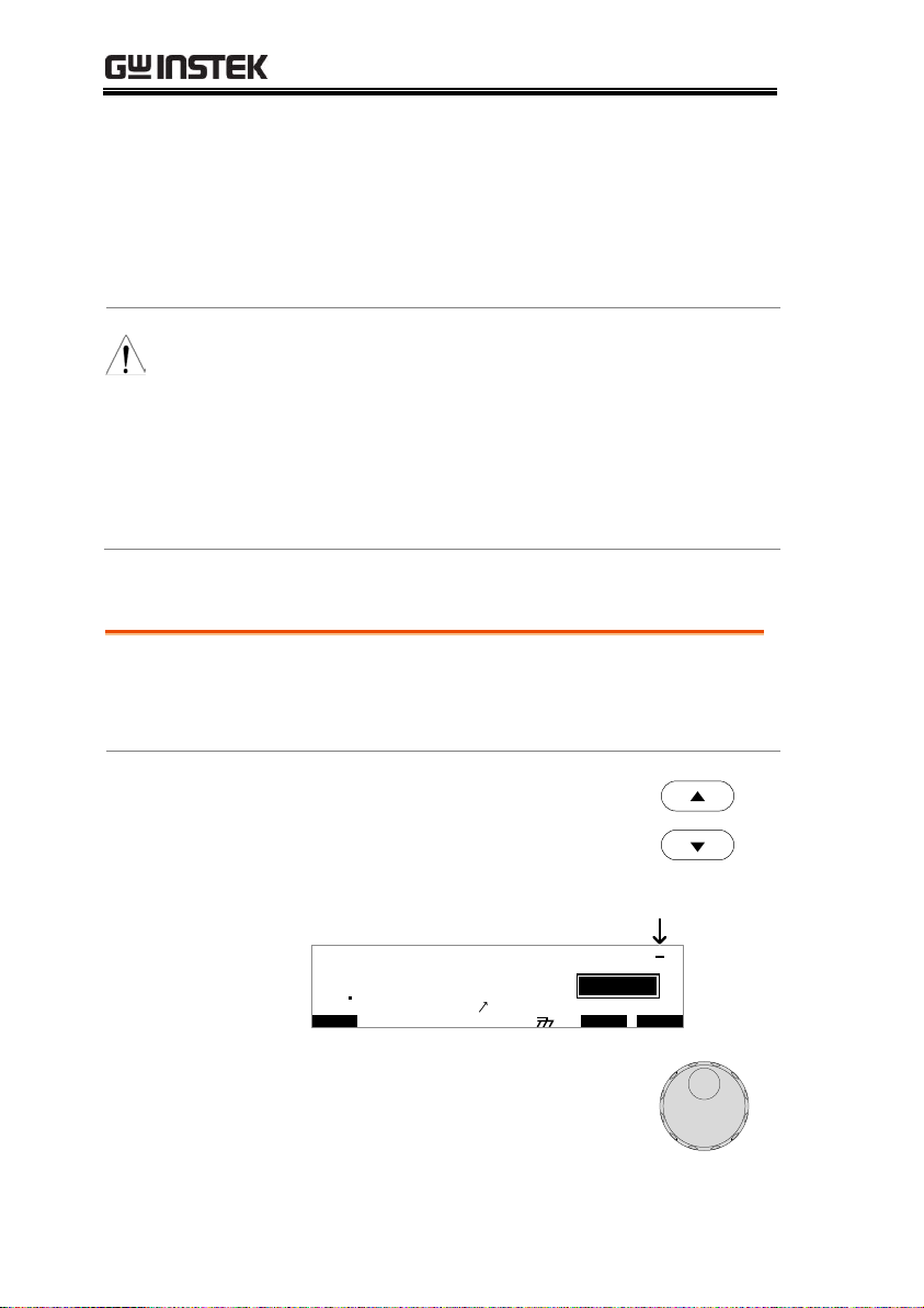
Background
The TIMER setting is used to set the test time
for the current test. The test time determines
how long the test voltage or current is applied
to the DUT. This test time does not include
Ramp , initial start time or discharge time
(note: GB does not have Ramp or discharge
times). The test time can be set from 0.5 seconds
to 999.9 seconds for ACW, DCW and GB and
1.0 second to 999.9 seconds for IR, with a
resolution of 0.1 seconds for all modes. The
timer can be turned off when in the special
MANU test mode when using the ACW or
DCW test functions.
Each test has an initial test time of 100ms and a
discharge time (except GB). The total discharge
time depends on the DUT and test voltage.
Discharge time
Test V
time
Start V
Initial time
(100ms)
TEST TIMERAMP
Steps
1. Press the TIMER soft-key or use
the UP/DOWN arrow keys to
bring the cursor to the TIMER
setting.
I M ET R
OR
Setting the Test Time (Timer)
46
Page 47

OPERATION
I R G B
m A
A CW D CW I / LH O I M ET R
E
F R E Q = 0 H z 6
0
100
k V
IDE
MT I E = 0 0 1 . 0 SR
0 0 m AER F =# 0 .0MM A UN N A_
1 . 0 0 m A0L ES = 0T
0 0 . 1 S0AM P =R
T2M A NU = * * * - 0 0
cursor
2. Use the scroll wheel to set the
TIMER value.
ACW
DCW
IR
GB
000.5s~999.9s
000.5s~999.9s
001.0s~999.9s
000.5s~999.9s
Note
With the ACW test function, when the test current
is between 30mA and 40mA (GPT-98XX) or 80mA
and 100mA (GPT-99XX), the ramp time + test time
cannot exceed 240 seconds. At this current level,
the tester also needs to pause after a test for a
time equal to or greater than the output time. See
the specifications on page 161 for details.
Special Manual
Mode
When in special MANU test mode (page 71) the
Timer can be turned off when using the DCW
or ACW test function.
Hold the TIMER soft-key for 3
seconds to turn the timer off.
I M ET R
Note
The timer can only be turned off under special
MANU test mode, however there is a limitation:
The timer cannot be turned off (limited to 240s) if
the test current is between 30mA and 40mA (GPT98XX) or 80mA and 100mA (GPT-99XX) in ACW
mode.
The discharge time and initial test time cannot be
edited.
47
Page 48
GPT-9000 Series User Manual
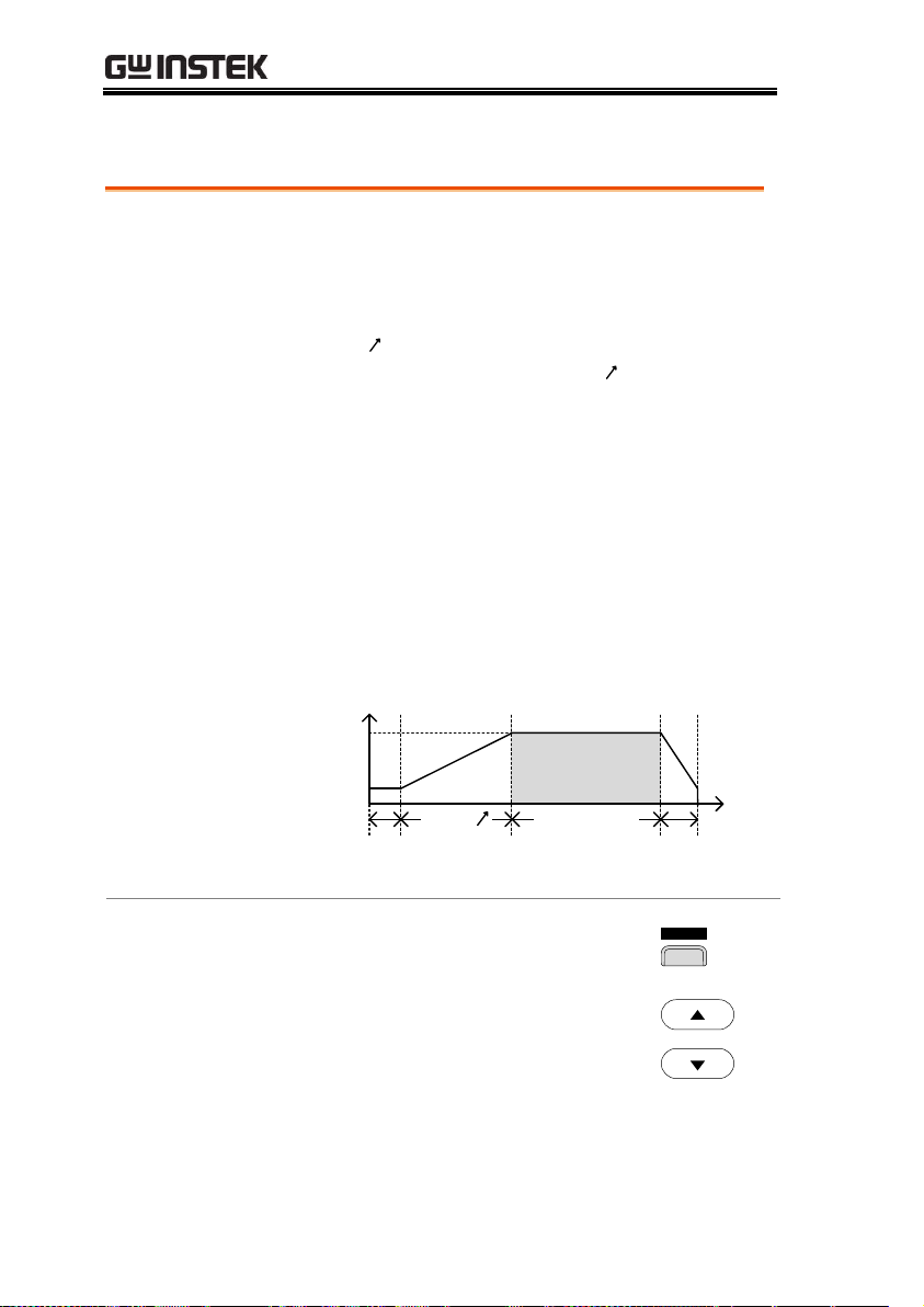
Background
The Ramp Up time is the total time taken for
the tester to reach the test voltage level. The
Ramp Up time starts after the initial time
(100ms) with a start voltage of 50 volts. The
Ramp Up time can be set from 000.1 to 999.9
seconds. The Ramp Up time is only applicable
for ACW, DCW and IR tests.
Discharge time
Test V
time
Start V
Initial time
(100ms)
TEST TIMERAMP
Steps
1. Use the UP/DOWN arrow keys to
bring the cursor to the RAMP
setting.
I R G B
m A
A CW D CW I / LH O I M ET R
E
F R E Q = 0 H z 6
0
100
k V
IDE
MT I E = 0 0 1 . 0 SR
0 0 m AER F =# 0 .0MM A UN N A_
1 . 0 0 m A0L ES = 0T
0 0 . 1 S0AM P =R
T2M A NU = * * * - 0 0
cursor
2. Use the scroll wheel to set the
RAMP value.
ACW
DCW
IR
000.1s~999.9s
000.1s~999.9s
000.1s~999.9s
Note
The discharge time and initial test time cannot be
edited.
Setting the Ramp Up Time
48
Page 49
OPERATION
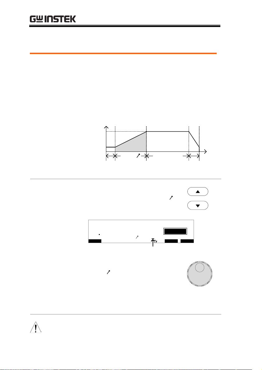
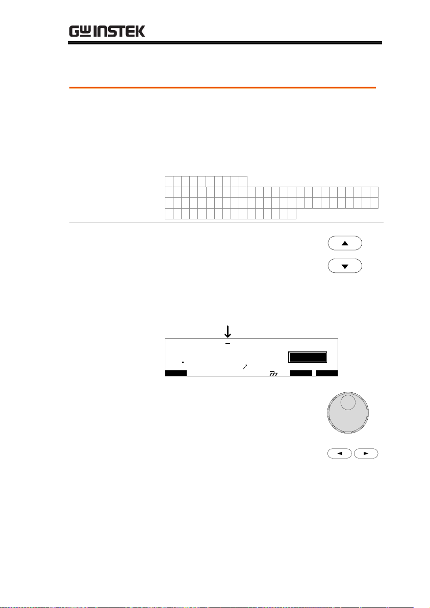
Background
Each manual test can have a user-defined test
file name (default: MANU_NAME) up to 10
characters long. See the character list below for
the allowed characters.
Character List
0 1 2 3 4 5 6 7 8 9
W X Y ZM VO P RQ T USNLA B C D E F G H I J K
w x y zm vo p rq t usnla b c d e f g h i j k
+ - * / _ = : Ω ? ( ) < > [ ]
Steps
1. Use the UP/DOWN arrow keys to
bring the cursor to the MANU test
file name at the top of the screen.
The test file name is initially set as
MANU_NAME.
I R G B
m A
A CW D CW I / LH O I M ET R
E
F R E Q = 0 H z 6
0
100
k V
IDE
MT I E = 0 0 1 . 0 SR
0 0 m AER F =# 0 .0MM A UN N A_
1 . 0 0 m A0L ES = 0T
0 0 . 1 S0AM P =R
T2M A NU = * * * - 0 0
cursor
2. Use the scroll wheel to scroll
through the available characters.
3. Press the Left/Right arrow keys to
go the next character.
4. The MANU test file name is set when the
current test setting is saved or when the cursor
is moved to another setting.
Creating a MANU Test File Name
49
Page 50
GPT-9000 Series User Manual
Background
ARC detection, otherwise known as flashover
detection, detects fast voltage or current
transients that are not normally detected. Arcing
is usually an indicator of poor withstanding
insulation, electrode gaps or other insulating
problems that cause temporary spikes in current
or voltage during ACW and DCW testing.
There are three ARC detection settings: OFF,
ON AND CONTINUE, ON AND STOP.
The ON AND CONTINUE setting will detect
arcs over the ARC current level and continue
the test, the ON AND STOP setting will stop the
test when an arc is detected.
ARC mode settings only apply to ACW and
DCW tests.
Steps
1. Press the UTILITY key on the front
panel when the tester is in EDIT
status. The tester will go to the
MANU Utility for the current test.
UTILITY
L I T Y IM A UN U T 2M A N U = * * * - 0 0
A R C M D E : OO FF
G RO U N D MO D E : NO
P A S S H L D :O O FF
F A I L M D E :O
PS T O
M A X H O L D : O F F
Note
The MANU UTILITY settings only apply to the
selected MANU test.
2. Use the UP/DOWN arrow keys to
move to the ARC MODE setting.
Setting the ARC Mode
50
Page 51

OPERATION
3. Use the scroll wheel to set the ARC
mode.
ARC MODES:
OFF, ON AND CONTINUE,
ON AND STOP
4. Press the EDIT/SAVE key to save
and exit the MANU Utility and go
back to EDIT status.
EDIT/SAVE
Note
The ESC key can be pressed at any time in the
Utility menu to cancel and exit.
5. If the ARC MODE was set to either ON AND
CONTINUE, or ON AND STOP, the ARC
current level can be edited.
6. Use the UP/DOWN arrow keys to
move the cursor to the ARC setting.
7. Use the scroll wheel to edit the
ARC level.
GPT-98XX:
ACW
DCW
1.000mA~080.0mA
1.000mA~020.0mA
GPT-99XX:
ACW
DCW
2.000mA~200.0mA
2.000mA~040.0mA
51
Page 52

GPT-9000 Series User Manual
Note
The ARC setting range is directly related to the HI
SET current limit.
ACW: GPT-98XX
HI SET Limit
ARC Range
0.001mA~0.999mA
1.000mA ~2.000mA
01.00mA~09.99mA
01.00mA ~20.00mA
010.0mA~042.0mA
001.0mA ~080.0mA
ACW: GPT-99XX
HI SET Limit
ARC Range
0.001mA~1.100mA
2.000mA
01.11mA~11.00mA
02.00mA ~20.00mA
011.1mA~110.0mA
002.0mA ~200.0mA
DCW: GPT-98XX
HI SET Limit
ARC Range
0.001mA~0.999mA
1.000mA ~2.000mA
01.00mA~09.99mA
01.00mA ~20.00mA
010.0mA~011.0mA
001.0mA ~020.0mA
DCW: GPT-99XX
HI SET Limit
ARC Range
0.001mA~1.100mA
2.000mA
01.11mA~11.00mA
02.00mA ~20.00mA
011.1mA~021.0mA
002.0mA ~040.0mA
52
Page 53

OPERATION
Background
The PASS HOLD settings only apply to the
selected test in an AUTO test. When the PASS
HOLD setting is set to ON, a PASS judgment is
held until the START button is pressed.
Note
The PASS HOLD setting only applies to AUTO
tests. This setting is ignored when running a
single MANU test.
Steps
1. Press the UTILITY key on the front
panel when the tester is in EDIT
status. The display will go from the
normal EDIT status to the MANU
Utility menu for the current test.
UTILITY
L I T Y IM A UN U T 2M A N U = * * * - 0 0
A R C M D E : OO FF
G RO U N D MO D E : NO
P A S S H L D :O O FF
F A I L M D E :O
PS T O
M A X H O L D : O F F
Note
The MANU UTILITY settings only apply to the
selected MANU test.
2. Use the UP/DOWN arrow keys to
move to the PASS HOLD setting.
3. Use the scroll wheel to set PASS
HOLD.
PASS HOLD
OFF, ON
4. Press the EDIT/SAVE key to save
and exit the MANU Utility menu.
EDIT/SAVE
Setting PASS HOLD
53
Page 54

GPT-9000 Series User Manual
Note
The ESC key can be pressed at any time in the
MANU Utility menu to cancel and exit.
Background
The FAIL MODE settings only apply to the
selected test in AUTO tests.
FAIL MODE has three options, CONTINUE,
HOLD and STOP.
When FAIL MODE is set to CONTINUE the
tester will continue testing after a FAIL
judgment.
When set to HOLD, the tester will hold the test
on a FAIL judgment, and then continue testing
after the START key is pressed.
The STOP mode will completely stop the test
after a FAIL judgment.
Note
The FAIL MODE setting only applies to AUTO
tests. This setting is ignored when running
MANU tests.
Steps
1. Press the UTILITY key on the front
panel when the tester is in
MANU/EDIT status. The display
will go from the normal EDIT
status to the MANU Utility menu
for the current test.
UTILITY
L I T Y IM A UN U T 2M A N U = * * * - 0 0
A R C M D E : OO FF
G RO U N D M OD E : NO
P A S S H L D :O O FF
F A I L M D E :O
PS T O
M A X H O L D : O F F
Setting FAIL MODE
54
Page 55

OPERATION
2. Use the UP/DOWN arrow keys to
move to the FAIL MODE setting.
3. Use the scroll wheel to set FAIL
MODE.
FAIL MODE
CONTINUE, HOLD, STOP
4. Press the EDIT/SAVE key to save
and exit the MANU Utility menu.
EDIT/SAVE
Note
The ESC key can be pressed at any time in the
MANU Utility menu to cancel and exit.
Background
The MAX HOLD setting will hold the
maximum current measured in the ACW and
DCW tests or the maximum resistance
measured in IR and GB tests.
Steps
1. Press the UTILITY key on the front
panel when the tester is in EDIT
status. The display will go from the
normal EDIT status to the MANU
Utility menu for the current test.
UTILITY
L I T Y IM A UN U T 2M A N U = * * * - 0 0
A R C M D E : OO FF
G RO U N D MO
P A S S H L D :O O FF
F A I L M D E :O
PS T O
M A X H O L D : O F F
D E : NO
Note
The MANU UTILITY settings only apply to the
selected MANU test.
Setting MAX HOLD
55
Page 56

GPT-9000 Series User Manual
2. Use the UP/DOWN arrow keys to
move to the MAX HOLD setting.
3. Use the scroll wheel to set MAX
HOLD.
MAX HOLD
OFF, ON
4. Press the EDIT/SAVE key to save
and exit the MANU Utility menu.
EDIT/SAVE
Note
The ESC key can be pressed at any time in the
MANU Utility menu to cancel and exit.
Background
When GROUND MODE is set to ON, the GPT9000 grounds the return terminal to the ground.
This mode is best for DUTs that are grounded
to an earth ground by their chassis, fixtures or
operation environment. This mode measures
the potential of the HIGH VOLTAGE terminal
with respect to earth ground. This means that
any stray capacitance/resistance that leaks to
earth ground will also be measured. This is the
safest testing mode, though potentially not as
accurate.
When GROUND MODE is set to OFF, the
return terminal is floating with respect to the
earth ground. This mode is for DUTs that are
floating and not directly connected to an earth
ground. This is more accurate than when
GROUND MODE is set to ON as any stray
capacitance/resistance that leaks to the earth
Setting the Grounding Mode
56
Page 57

OPERATION
ground from the DUT side of the testing circuit
will not be measured. For this reason, this
testing mode is able to measure to a higher
resolution.
The GROUND MODE is always set to OFF for
IR and GB tests.
GROUND MODE = ON, DUT grounded
High Voltage terminal
Return terminal
DUT
GPT-9000
stray
resistance,
capacitance
GROUND MODE = ON, DUT floating
High Voltage terminal
DUT
GPT-9000
stray
resistance,
capacitance
Return terminal
57
Page 58

GPT-9000 Series User Manual
GROUND MODE = OFF, DUT floating
High Voltage terminal
DUT
GPT-9000
stray
resistance,
capacitance
Return terminal
GPT-9804 (GB testing)
DUT
Source H
Source L
Sense H
Sense L
stray
resistance,
capacitance
GROUND MODE = OFF, DUT grounded
High Voltage terminal
DUT
GPT-9000
stray
resistance,
capacitance
Return terminal
GPT-9804 (GB testing)
DUT
Source H
Source L
Sense H
Sense L
stray
resistance,
capacitance
58
Page 59

OPERATION
Warning
When GROUND MODE is set to OFF, the DUT,
fixtures or connected instrumentation cannot be
grounded. This will short circuit the internal
circuitry during a test.
For ACW and DCW tests, if it is not known whether
the DUT test setup is grounded or not, always set
GROUND MODE to ON.
Only set GROUND MODE to OFF when the DUT
is floating electrically.
Steps
1. Press the UTILITY key on the front
panel when the tester is in EDIT
status. The display will go from the
normal EDIT status to the MANU
Utility menu for the current test.
UTILITY
L I T Y IM A UN U T 2M A N U = * * * - 0 0
A R C M D E : OO FF
G RO U N D MO D E :
P A S S H L D :O O FF
F A I L M D E :O
PS T O
M A X H O L D : O F F
NO
Note
The MANU UTILITY settings only apply to the
selected MANU test.
2. Use the UP/DOWN arrow keys to
move the cursor to the GROUND
MODE setting.
3. Use the scroll wheel to set the
GROUND MODE.
GROUND MODE
OFF, ON
4. Press the EDIT/SAVE key to save
and exit the MANU Utility menu.
EDIT/SAVE
59
Page 60
GPT-9000 Series User Manual
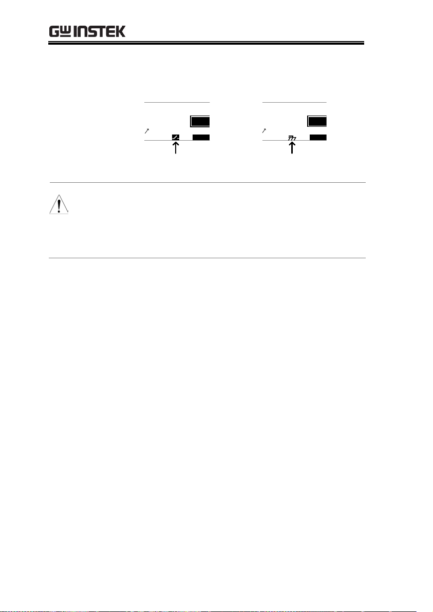
5. The GROUND MODE icon on the display
changes accordingly.
E
F R EQ = 0 H z 6
IDE
0 0 m AER F =# 0 .0MM A UN N A_
1 . 0 0 m A0L ES = 0T
0 0 . 1 S0A M P =R
T
GROUND
MODE = OFF
m A
E
F R E Q = 0 H z 6
IDE
0 0 m AER F =# 0 .0MM A UN N A_
1 . 0 0 m A0L ES = 0T
0 0 . 1 S0AM P =R
T
GROUND
MODE = ON
m A
Note
The ESC key can be pressed at any time in the
MANU Utility menu to cancel and exit.
IR and GB tests can only have GROUND MODE
set to OFF.
60
Page 61
OPERATION
Background
After all test parameters have been set, the test
can be saved. After a test is saved it can be used
when creating an AUTO test.
Warning
The special MANU number, 000, can be saved,
however it cannot be used for AUTO tests. See
page 71 for details.
Steps
1. When in EDIT status, press the
EDIT/SAVE key to save the
current test. This will enter the
VIEW status for the chosen test
number.
EDIT/SAVE
I R G B A CW D CW
E
F R E Q = 0 H z 6
0
100
k V
EIV
MT I E = 0 0 1 . 0 SR
0 0 m AER F =# 0 .0MM A UN N A_
1 . 0 0 m AIH ES = 0T
0 0 . 1 S0AM P =R
W2M A NU = * * * - 0 0
IDE
T
m A
2. The Status changes from EDIT to VIEW.
Note
Pressing the EDIT/SAVE key again will return the
tester back to EDIT status for the current test.
Saving and Exiting EDIT Status
61
Page 62

GPT-9000 Series User Manual
Background
A test can be run when the tester is in READY
status.
Note
The tester cannot start to run a test under the
following conditions:
A protection setting has been tripped; when a
protection setting has been tripped the
corresponding error message is displayed on
the screen. See page 159 for a comprehensive
list of the all the setting errors.
The INTERLOCK function is ON and the
Interlock key is not inserted in the signal I/O
port (page 100).
The STOP signal has been received remotely.
If Double Action is ON, ensure the START
button is pressed immediately after the STOP
button (<0.5s).
Note
When a test is running the voltage output
cannot be changed, unless the test is under the
special manual mode. See page 71 for details.
Steps
1. Ensure the tester is in VIEW status
for the current test. Save the
current test if necessary.
Page 61
I R G B
m A
A CW D CW
E
F R EQ = 0 H z 6
0
100
k V
EIV
MT I E = 0 0 1 . 0 SR
0 0 m AER F =# 0 .0
1 . 0 0 m AIH ES = 0T
0 0 . 1 S0A M P =R
W
VIEW status
MM A UN N A_2M A NU = * * * - 0 0
Running a MANU Test
62
Page 63

OPERATION
2. Press the STOP button to put the
tester into the READY status.
STOP
I R G B
m A
A CW D CW
E
F R EQ = 0 H z 6
0
100
k V
AER
MT I E = 0 0 1 . 0 SR
0 0 m AER F =# 0 .0
1 . 0 0 m AIH ES = 0T
0 0 . 1 S0A M P =R
D
MM A UN N A_2M A NU = * * * - 0 0
READY status
Y
3. The READY indicator will be lit
blue when in the READY status.
READY
4. Press the START button when the
tester is in the READY status. The
manual test starts automatically
and the tester goes into the TEST
status.
START
5. The TEST indicator will be lit
orange when in the TEST status.
TEST
I R G B A CW D C W
E
F R EQ = 0 H z 6
0
100
k V
SET
MT I E = 0 0 1 . 0 SR
0 0 m AER F =# 0 .0
1 . 0 0 m AIH ES = 0T
0 0 . 1 S0A M P =R
MM A UN N A_2M A NU = * * * - 0 0
TEST status
T
m A
00 00
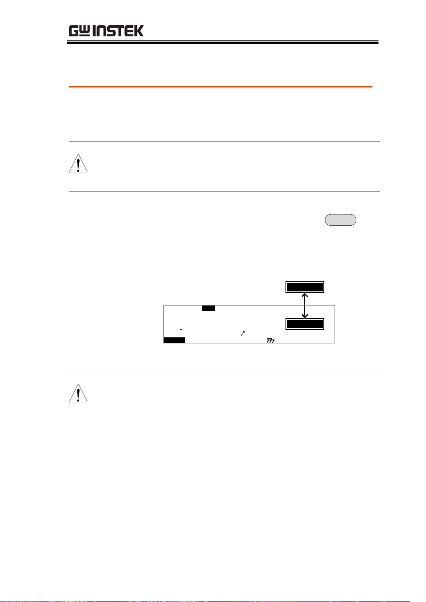
6. The test will start by showing the remaining
ramp up time, followed by the remaining test
time. The test will continue unit the test is
finished or the test is stopped.
63
Page 64
GPT-9000 Series User Manual
I R G B A CW D CW
E
F R EQ = 0 H z 6
0
100
k V
SET
MT I E = 0 0 3 . 2 SR
0 0 m AER F =# 0 .0
1 . 0 0 m AIH ES = 0T
0 0 . 1 S0A M P =R
MM A UN N A_2M AN U = * * * - 0 0
T
remaining TIMER time
00 37
m A
remaining RAMP time
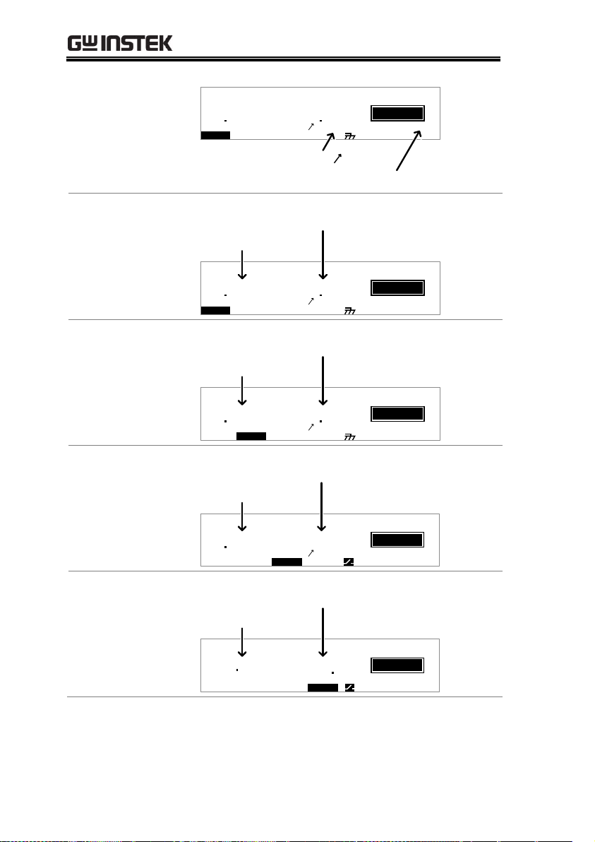
ACW Example
I R G B A CW D CW
E
F R E Q = 0 H z 6
0
100
k V
SET
MT I E = 0 0 3 . 2 SR
0 0 m AER F =# 0 .0
1 . 0 0 m AIH ES = 0T
0 0 . 1 S0AM P =R
MM A UN N A_2M A NU = * * * - 0 0
T
Test Voltage
Measured Current
00 37
m A
DCW Example
I R G B A CW D CW
E
0
100
k V
SET
MT I E = 0 0 3 . 2 SR
0 0 m AER F =# 0 .0
1 . 0 0 m AIH ES = 0T
0 0 . 1 S0AM P =R
MM A UN N A_2M A NU = * * * - 0 0
T
Test Voltage
Measured Current
00 56
m A
IR Example
I R G B A CW D CW
E
0
050
k V
SET
MT I E = 0 0 3 . 2 SR
0 0 M ΩER F =# 0 0
1 1 0 0 M ΩIH ES = T
0 0 . 1 S0AM P =R
MM A UN N A_2M A NU = * * * - 0 0
T
Test Voltage
Measured Resistance
1056
MΩ
GB Example
I R G B A CW D CW
E
F R E Q = 0 H z 6
0
3 01
A
SET
G B V = 0 . 6 2 2 V MT I E = 0 0 3 . 2 SR
. 0 m ΩER F =# 0 00
0 0 . 0 mΩIH ES = 3T
MM A UN N A_2M A N U = * * * - 0 0
T
Test Current
Measured Resistance
200 7
mΩ
64
Page 65

OPERATION
Stop the Test
1. To stop the test at any time when it
is running, press the STOP button.
The test will stop immediately.
When the STOP button is pressed,
a judgment is not made on the test.
All panel keys except the STOP
button are locked when the tester
is in STOP status.
STOP
I R G B A CW D CW
E
F R E Q = 0 H z 6
0
100
k V
OTS
MT I E = 0 0 1 . 0 SR
0 0 m AER F =# 0 .0
1 . 0 0 m AIH ES = 0T
0 0 . 1 S0AM P =R
MM A UN N A_2M A N U = * * * - 0 0
STOP status
P
m A
00 00
2. To put the tester back into READY
status, press the STOP button
again.
STOP
Exit TEST Status
To exit testing, press the
MANU/AUTO key when the
tester is in the READY status. The
tester will revert to the VIEW
status for the current test.
MANU/AUTO
I R G B
m A
A CW D CW
E
F R E Q = 0 H z 6
0
100
k V
EIV
MT I E = 0 0 1 . 0 SR
0 0 m AER F =# 0 .0
1 . 0 0 m AIH ES = 0T
0 0 . 1 S0A MP =R
W
MM A UN N A_2M A N U = * * * - 0 0
Note
Do not touch any terminals, test leads or any other
connections when the test is on.
65
Page 66
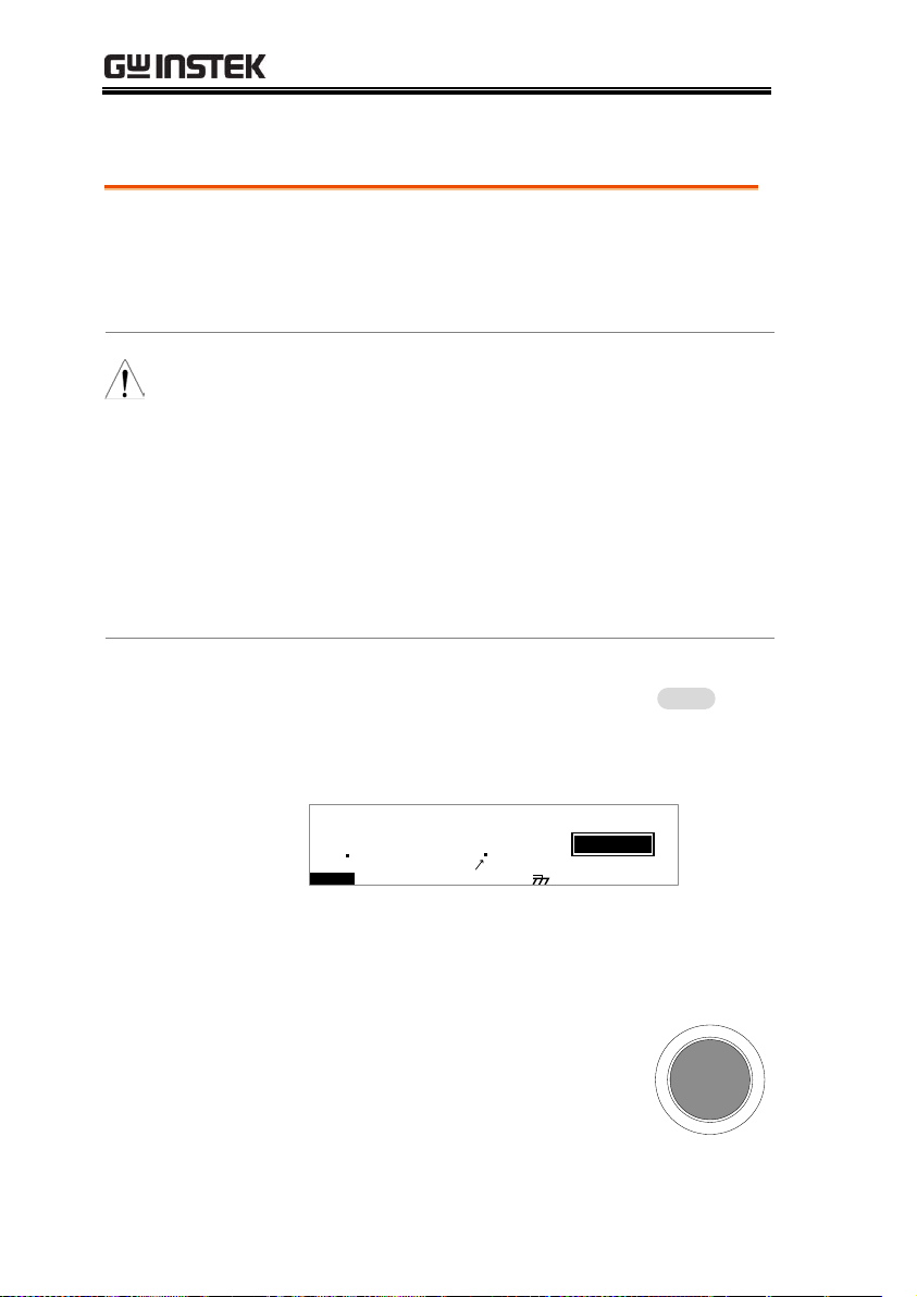
GPT-9000 Series User Manual
Background
If the test is allowed to run to completion (the
test is not stopped or a protection setting is not
tripped) then the tester will judge the test as
either PASS or FAIL.
Note
The test will be judged PASS when:
The HI SET and LO SET limits have not been
tripped during the test time.
The test will be judged FAIL when:
Either the HI SET or LO SET limit has been
tripped during the test time.
A protection setting has been tripped during
the test time. See page 159 for a list of error
messages.
PASS Judgment
1. When the test is judged as PASS,
PASS will be displayed, the buzzer
will sound and the PASS indicator
will be lit green.
PASS
I R G B A C W D CW
E
F R E Q = 0 H z 6
0
100
k V
SAP
MT I E = 0 0 1 . 0 SR
0 0 m AER F =# 0 .0
1 . 0 0 m AIH ES = 0T
0 0 . 1 S0A MP =R
MM A UN N A_2M A N U = * * * - 0 0
S
m A
00 37
2. The PASS judgment will be held on the display
until the STOP or START button is pressed.
Pressing the STOP button will
return the tester to the READY
status.
STOP
PASS / FAIL MANU Test
66
Page 67
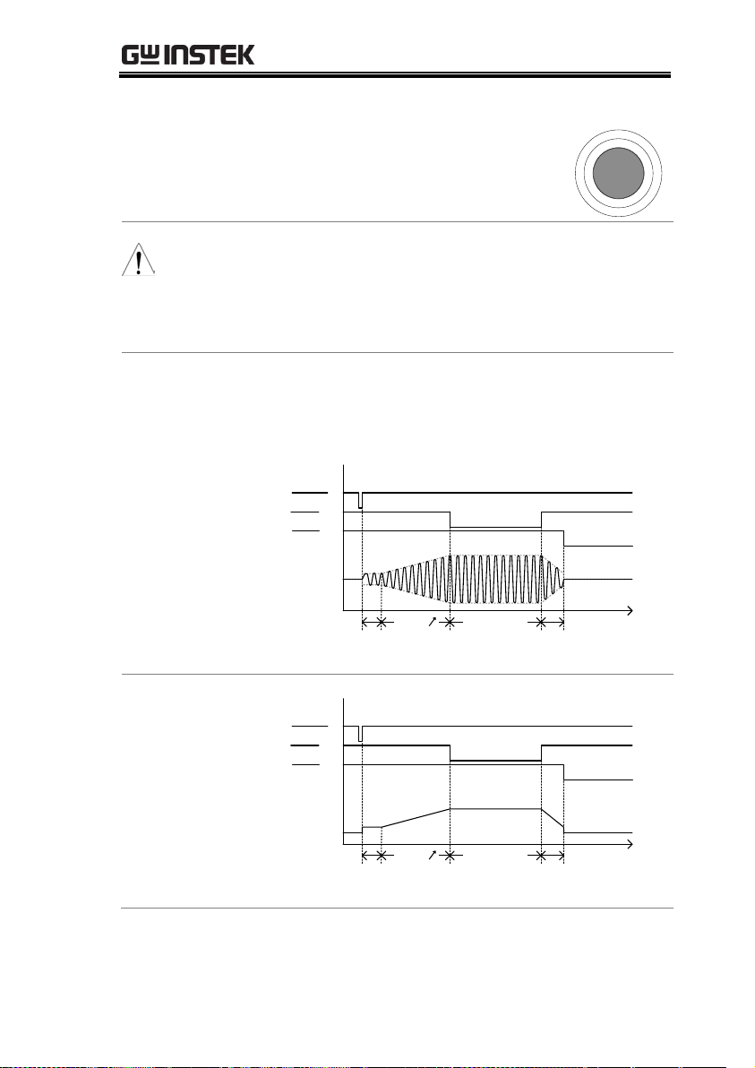
OPERATION
Pressing the START button will
restart the test.
START
Note
The buzzer will only sound if the Pass Sound is set
to ON. See page 97 for details.
The START button is disabled when the buzzer is
beeping.
PASS Timing
Diagrams
The timing diagrams below show the ACW, DCW,
IR and GB timing for the START status, TEST
status and PASS judgment.
ACW PASS
Timing
Discharge time
Output V
time
Initial time
(100ms)
START
TEST
PASS
RAMP TEST TIME
DCW PASS
Timing
Discharge time
Output V
time
Initial time
(100ms)
START
TEST
PASS
RAMP TEST TIME
67
Page 68
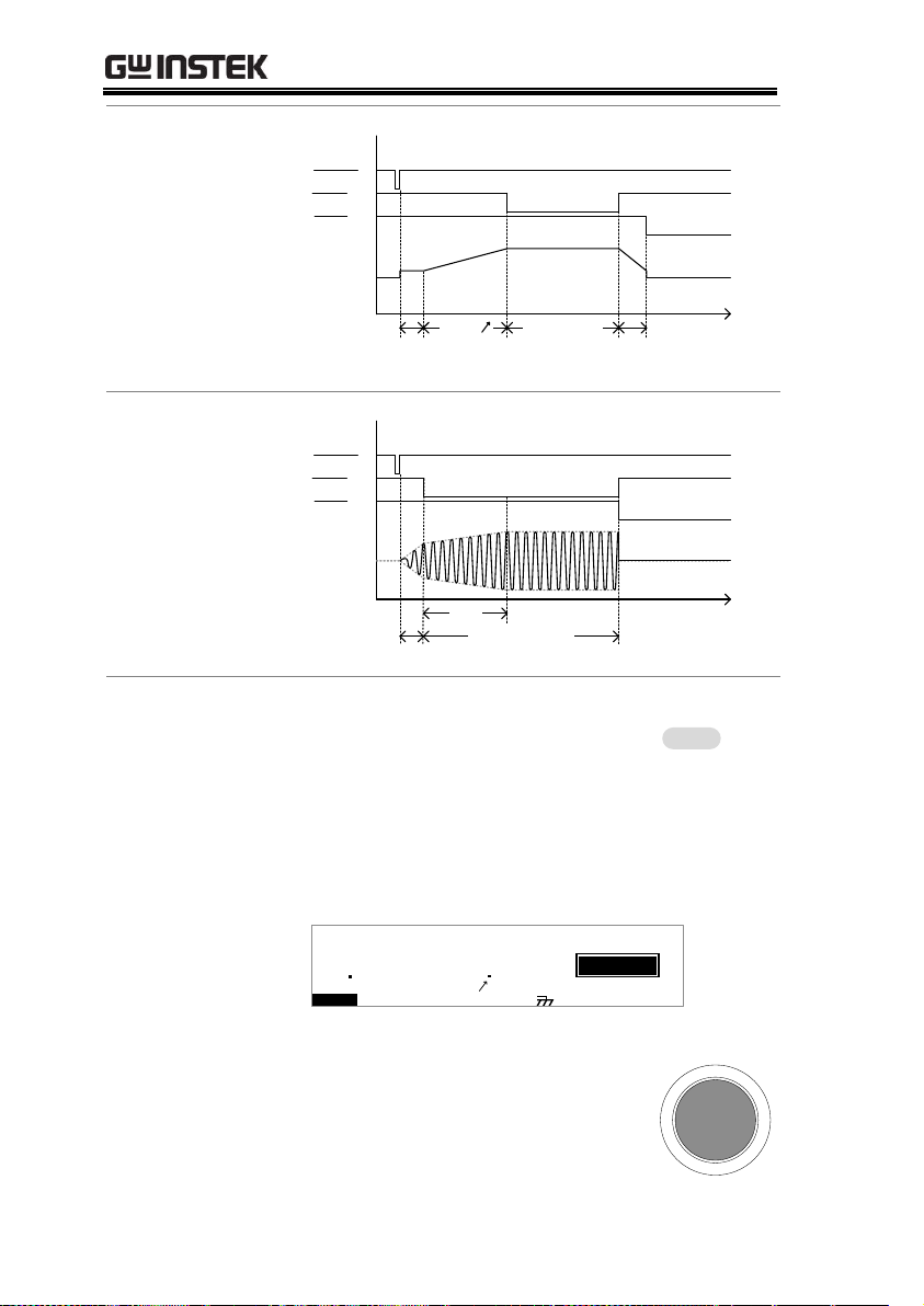
GPT-9000 Series User Manual
IR PASS Timing
Discharge time
Output V
time
Initial time
(100ms)
START
TEST
PASS
RAMP TEST TIME
GB PASS Timing
Output I
time
START
TEST
PASS
0.5s
Initial time
(100ms)
Total Test Time
FAIL Judgment
1. When the test is judged as FAIL,
FAIL will be displayed, the buzzer
will sound and the FAIL indicator
will be lit red.
As soon as a test is judged FAIL,
power is cut from the terminals.
FAIL
I R G B A C W D CW
F R E Q = 0 H z 6
0
100
k V
IAF
MT I E = 0 0 1 . 0 SR
0 0 m AER F =# 0 .0
1 . 0 0 m AIH ES = 0T
0 0 . 1 S0A MP =R
2MA UN 0 0_2MA N U = * * * - 0 0
L
m A
01 37
2. The FAIL judgment will be held on
the display until the STOP button
is pressed. Pressing the STOP
button twice will return the tester
to the READY status.
STOP
68
Page 69

OPERATION
3. The READY indicator will be lit
blue in the READY status.
READY
I R G B
m A
A CW D CW
E
F R EQ = 0 H z 6
0
100
k V
AER
MT I E = 0 0 1 . 0 SR
0 0 m AER F =# 0 .0
1 . 0 0 m AIH ES = 0T
0 0 . 1 S0A M P =R
D
MM A UN N A_2M A NU = * * * - 0 0
READY status
Y
Note
The buzzer will only sound if Fail Sound is set to
ON. See page 97 for details.
FAIL Timing
Diagrams
The timing diagrams below show the ACW, DCW,
IR and GB timing for the START status, TEST
status and FAIL judgment.
ACW FAIL Timing
START
TEST
FAIL
Discharge time
Output V
time
Initial time
(100ms)
RAMP
TEST TIME
DCW FAIL Timing
FAIL
Discharge time
Output V
time
Initial time
(100ms)
RAMP
START
TEST
TEST TIME
69
Page 70

GPT-9000 Series User Manual
IR FAIL Timing
START
TEST
FAIL
Discharge time
Output V
time
Initial time
(100ms)
RAMP TEST TIME
GB FAIL Timing
Output I
time
START
TEST
FAIL
0.5s
Initial time
(100ms)
Total Test Time
70
Page 71

OPERATION
Background
The Zeroing function is used to determine the
resistance of the test leads for GB tests. When a
zero check is performed, the reference is
automatically set to the measured resistance of
the test leads.
This function is only available for GB testing.
Steps
1. Ensure the tester is in VIEW status
for the current GB test. Save the
current test if necessary.
Page 61
I R GB A CW D C W
E
F R E Q = 0 H z 6
EIV
G B V = V MT I E = 0 0 3 . 2 SR
. 0 m ΩER F =# 0 00
0 0 . 0 mΩIH ES = 3T
MM A UN N A_2M A N U = * * * - 0 0
W
mΩ
0
3 01
A
2. Short the positive and negative alligator clips as
shown below.
3. Press the STOP button to put the
tester into the READY status.
STOP
Zeroing of the Test Leads (GB only)
71
Page 72
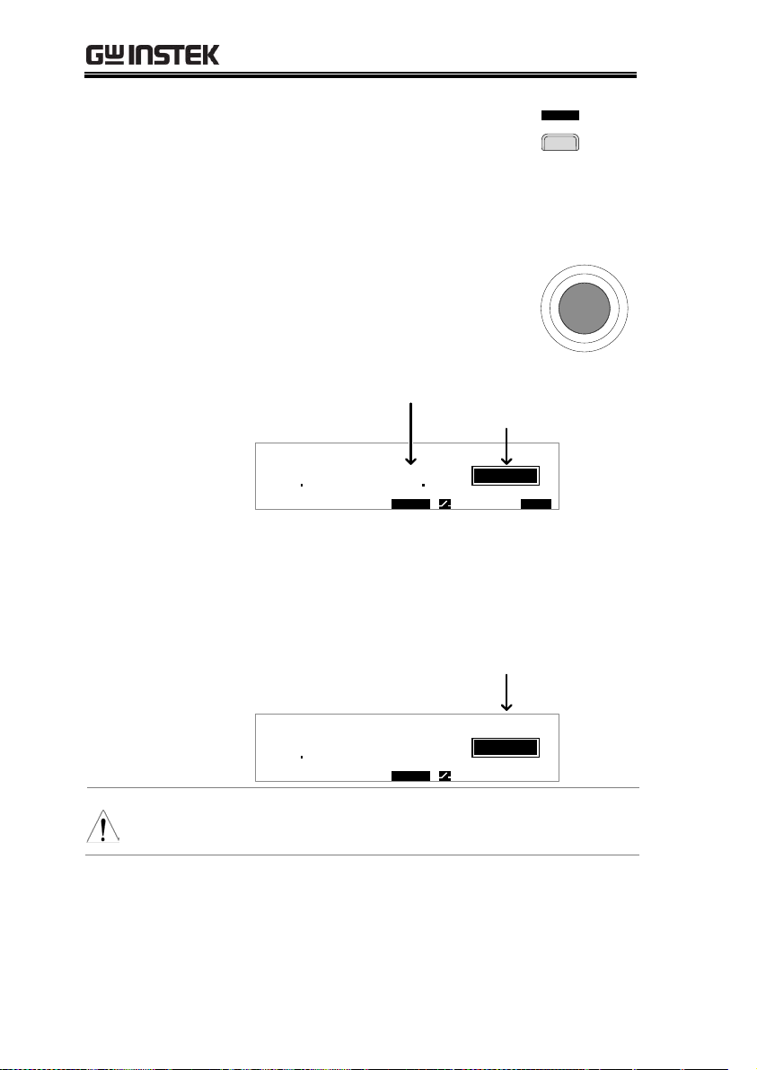
GPT-9000 Series User Manual
4. The ZERO function can be
activated by pressing the
corresponding soft-key in the
READY status. The ZERO soft-key
will be highlighted.
E R OZ
5. Press the START button to perform
the zero check. The tester will go
into the ZERO status.
START
0
3 01
A
Z E R 0 I R G B A CW D CW
E
F R E Q = 0 H z 6
REZ
G B V = 0 . 6 2 2 V MT I E = 0 0 3 . 2 SR
. 0 m ΩER F =# 0 00
0 0 . 0 mΩIH ES = 3T
MM A UN N A_2M A N U = * * * - 0 0
O
Measured Resistance
200 7
mΩ
ZERO status
6. When the zero check has finished, the tester
will return back to the VIEW status. The
resistance of the test leads will be automatically
set as the Reference value.
0
3 01
A
I R G B A CW D CW
E
F R E Q = 0 H z 6
EIV
G B V = V MT I E = 0 0 3 . 2 SR
. 7 m ΩER F =# 0 02
0 0 . 0 mΩIH ES = 3T
MM A UN N A_2M A N U = * * * - 0 0
W
mΩ
Reference value
Note
Remember to replace the test leads to the proper
position on the DUT before testing.
72
Page 73

OPERATION
I<SET
If SOURCE H/L terminals are open or poorly
connected, then an I<SET error will appear on the
screen. Stop the test and re-check the connection
again and try again.
Z E R 0 I R G B A CW D CW
E
F R E Q = 0 H z 6
IAF
G B V = 5 . 6 2 2 V MT I E = 0 0 3 . 2 SR
. 0 m ΩER F =# 0 00
0 0 . 0 mΩIH ES = 3T
MM A UN N A_2M A N U = * * * - 0 0
L
I<SET error message
FAIL status
< I S E T
R = 0
Stop the test and perform the zero check again.
Z E R 0 I R G B A CW D CW
E
F R E Q = 0 H z 6
IAF
G B V = 5 . 6 2 2 V MT I E = 0 0 3 . 2 SR
. 0 m ΩER F =# 0 00
0 0 . 0 mΩIH ES = 3T
MM A UN N A_2M A N U = * * * - 0 0
L
R = 0 error message
FAIL status
= R 0
73
Page 74

GPT-9000 Series User Manual
Special Test
Mode Overview
When MANU number 000 is selected, the
special test mode is activated. Under the special
test mode, the voltage can be changed during a
test, in real time (ACW, DCW only). The test
function can also be changed when in READY
or VIEW status, unlike under normal operation.
Separate settings can be saved under the special
test mode for each of the testing functions:
ACW, DCW, IR and GB. This means a different
ACW, DCW, IR and GB test setup can be saved
for MANU number 000.
Sweep Function
Overview
The GPT-9903 and 9904 also has access to the
sweep mode function. The sweep function
creates a graph of one of the ACW, DCW, IR or
GB tests in the special manual mode. The graph
will plot the output voltage, current or
resistance versus time. After the test has been
completed, the test current, voltage or
resistance at any point in time can be viewed in
the graph.
Below is an example of the resultant sweep plot
of a DCW test where a DC voltage is ramped
up to a user-defined level until the HI SET
current level has been tripped or the test time
runs out.
Special MANU Test Mode (000)
74
Page 75

OPERATION
Test V
Test I
time
Start time
RAMP TIME
Legend: Voltage: Current
TEST time
Voltage
Current
The test items that are plotted on the sweep
graph depend on the type of test that is
performed.
TEST
Graph Test Items
ACW
Test voltage, test current (V, I)
DCW
Test voltage, test current (V, I)
IR
Test current, test resistance (I, R)
GB
Test voltage, test resistance (V, R)
Steps
1. Choose MANU number 000 to
enter the special test mode.
Page 38
2. The settings of a previous test can
be loaded by pressing the
corresponding soft-key in the
VIEW or READY status.
For example, if you are currently in
DCW mode, pressing the ACW
key will load the ACW settings
that were previously used in the
special manual mode.
A CW
Example:
ACW
75
Page 76
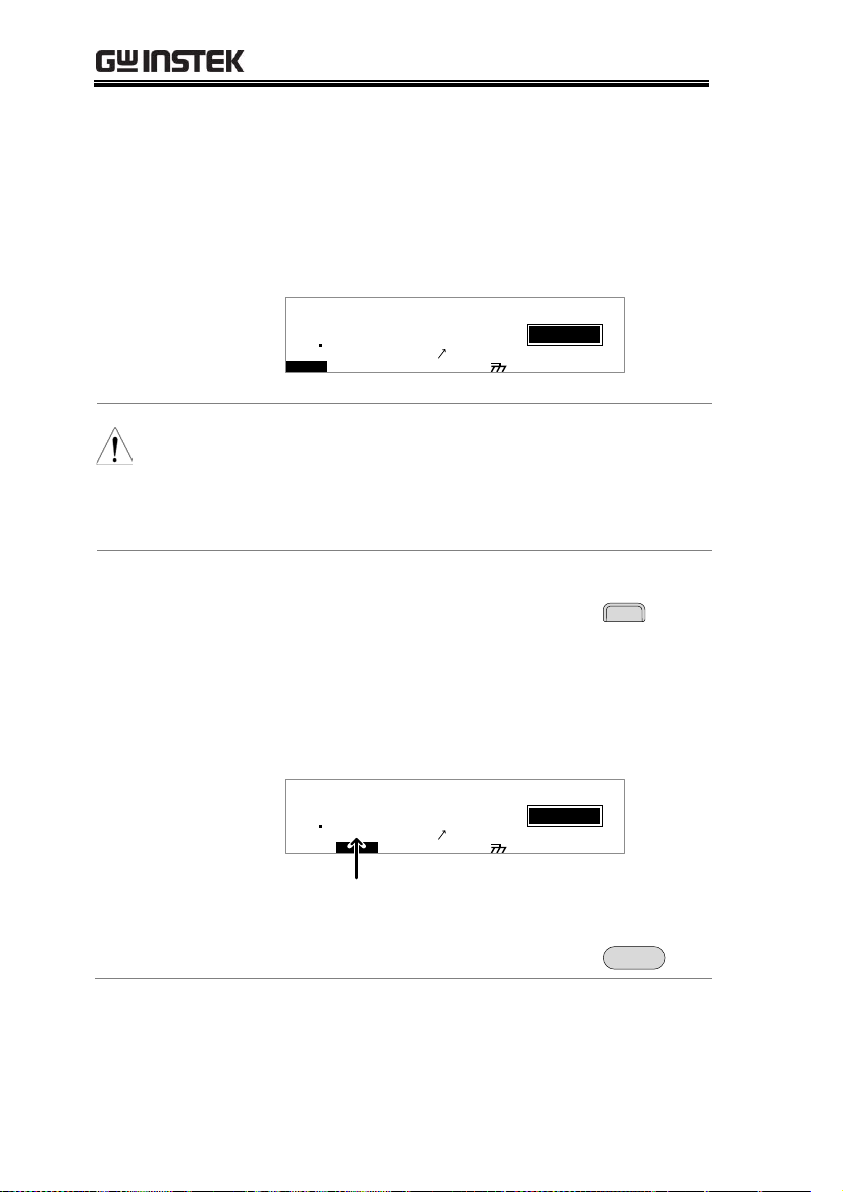
GPT-9000 Series User Manual
3. Set all the necessary parameters for
a test and save.
Note: A different test setup can be
saved for each test function (ACW,
DCW, IR and GB).
Pages 39~61
I R G B A CW D CW
E
F R E Q = 0 H z 6
0
100
k V
EIV
S T A . t = 0 0 0 0 . 1 S MT I E = 0 0 1 . 0 SR
0 0 m AER F =# 0 .0
1 . 0 0 m AIH ES = 0T
0 0 . 1 S0AM P =R
W
MM A UN N A_0M A N U = * * * - 0 0
m A
ES W E S T A . tP
GPT-99XX shown.
Note
The TIMER settings can be set OFF when in the
special test mode for ACW and DCW tests.
If the TIMER settings are set to OFF, the sweep
function will not produce a graph.
Setting the Sweep
Start Time
1. When in the VIEW status, press the
STA.t key and set the starting time
for the sweep graph. Make sure
that the sweep start time is
significantly less than the test time.
This setting is only applicable for
the GPT-9903 and GPT-9904.
T A .S t
I R G B A CW D CW
E
0
100
k V
EIV
S T A . t = 0 0 0 0 . 1 S MT I E = 0 0 1 . 0 SR
0 0 m AER F =# 0 .0
1 . 0 0 m AIH ES = 0T
0 0 . 1 S0AM P =R
W
MM A UN N A_0M A N U = * * * - 0 0
m A
ES W E S T A . tP
Start time
2. Press the EDIT/SAVE key to save
the Start time.
EDIT/SAVE
76
Page 77

OPERATION
Running the Test
1. In special test mode (000), tests are
started and stopped in the same
way as for the normal manual test
mode. See page 62 for details.
Page 62
2. If required, the scroll wheel can be
used to set the voltage level in realtime as the test is running (this
does not apply to IR or GB tests).
ACW
DCW
0.100kV ~ 5kV
0.100kV ~ 6kV
Results
Test judgments are the same as
those for the normal manual tests.
Please see the PASS/FAIL MANU
Test section for details.
Page 66
View Sweep
Graph
Unlike normal manual tests, the special test
mode also has an option to view the resultant
test as a sweep graph.
This option is only available for the GPT-9903
and GPT-9904.
Steps
1. When the test has finished, press
the SWEEP key to view the results
of the sweep in a graph.
WE ES P
Graph Test Items:
TEST
Primary
Secondary
ACW
Test voltage
test current
DCW
Test voltage
test current
IR
Test current
test resistance
GB
Test voltage
test resistance
77
Page 78

GPT-9000 Series User Manual
DCW Example
D CW
Primary item
Secondary item
I ( m A ) :
V ( k V ) :
0 . 2 0 0
0 0 . 5 1
T ( S ) :
0 0 0 4 . 5
V
I
Test Time CursorSTA.t time
2. Use the scroll wheel to move the
cursor on the time axis (x-axis).
The measured values for the
primary and secondary items at
that particular point in time are
shown on the left-hand side.
Remove Lines
from the Graph
1. Pressing the F5 key
will toggle the
primary test item
on/off.
2. Pressing the F6 key
will toggle the
secondary test item
on/off.
V
I
Toggle
voltage line
Toggle
current line
Example: DCW test
Exit the Results
Graph
To exit the graph, press the ESC
key. You will be returned back to
MANU mode/VIEW status.
ESC
78
Page 79

OPERATION
Background
The tester must first be put into AUTO mode to
create or run automatic tests.
Up to 100 automatic tests can saved/recalled.
Steps
1. If the tester is in MANU mode,
press and hold the MANU/AUTO
key for three seconds. This will put
the tester into Auto mode.
The tester can only switch between
AUTO and MANU mode when in
the VIEW status.
MANU/AUTO
Automatic Tests
This section describes how to create, edit and run automatic tests.
Automatic tests allow you to link together up to 16 different
MANU tests and run them sequentially. Each stored MANU test is
used as a test step when creating an AUTO test.
Choose/Recall an Automatic Test→ from page 79
Edit Automatic Test Settings → from page 81
Adding a Step to the Automatic Test → from page 82
Creating an AUTO Test File Name → from page 83
Saving and Exiting EDIT Status → from page 84
Automatic Test Page View → from page 85
Running an Automatic Test → from page 88
Automatic Test Results → from page 92
Before operating the GPT-9000 please read the safety precautions as
outlined in the Set Up chapter on page 22.
Choose/Recall an Automatic Test
79
Page 80

GPT-9000 Series User Manual
I R G B A CW D CW
E
F R E Q = 0 H z 6
0
100
k V
EIV
MT I E = 0 0 1 . 0 SR
0 0 m AER F =# 0 .0
1 . 0 0 m AIH ES = 0T
0 0 . 1 S0AM P =R
M A NU = * * * - 0 0 1
W
MA U OT N A_0A U T O = 0 0 1 - 1 0
VIEW status
MM A UN N A_ E
m A
Note
If the chosen automatic test has not yet been
setup, then the screen will be blank except for the
status and mode.
E
EIV
M A NU = * * * - 0 0 1
W
MA U OT N A_*A U T O = 0 0 1 - * *
VIEW status
MM A UN N A_ E
2. Use the scroll wheel to choose the
AUTO number.
AUTO #
001~100
I R G B A CW D CW
E
F R E Q = 0 H z 6
0
100
k V
EIV
MT I E = 0 0 1 . 0 SR
0 0 m AER F =# 0 .0
1 . 0 0 m AIH ES = 0T
0 0 . 1 S0AM P =R
W
MA U OT N A_0A U T O = 0 0 1 - 1 0
AUTO number
m A
Note
The AUTO number can only be chosen in VIEW
status. If in the EDIT status, switch to the VIEW
status by pressing the EDIT/SAVE or ESC key.
80
Page 81

OPERATION
Background
To edit an automatic test, the tester must be in
EDIT status.
Any settings or parameters that are edited only
apply to the currently selected AUTO number.
Steps
1. Press the EDIT/SAVE key when in
VIEW status to enter the EDIT
status. This will enter the EDIT
status for the chosen AUTO
number.
EDIT/SAVE
I R G B
m A
A CW D CW A D D
E
F R E Q = 0 H z 6
0
100
k V
IDE
MT I E = 0 0 1 . 0 SR
0 0 m AER F =# 0 .0MA U OT N A_
1 . 0 0 m AIH ES = 0T
0 0 . 1 S0AM P =R
T1A U T O = 0 0 1 - 0 0
EIV
W
2. The Status changes from VIEW to EDIT. The
tester is now ready to edit the current AUTO
test.
Note
Pressing the EDIT/SAVE key again will save the
settings or pressing the ESC will cancel the
settings for the current AUTO test and return back
to VIEW status.
Edit Automatic Test Settings
81
Page 82

GPT-9000 Series User Manual
Background
Up to 16 MANU tests (steps) can be added to
an automatic (AUTO) test. Each step is added
in a sequential order.
Steps
1. Press the DOWN arrow keys to
bring the cursor to the MANU
number.
I R G B
cursor
MANU number
m A
A CW D CW A D D
E
F R E Q = 0 H z 6
0
100
k V
IDE
MT I E = 0 0 1 . 0 SR
0 0 m AER F =# 0 .0MM A UN N A_
1 . 0 0 m AIH ES = 0T
0 0 . 1 S0AM P =R
T1A U T O = 0 0 1 - 0 0
2. Use the scroll wheel to choose a
MANU number to add to the
automatic test.
MANU number
001~100
3. Press the ADD soft-key to add the
selected manual test to the
automatic test as another step.
A D D
4. Repeat steps 2 and 3 for any other tests that you
wish to add to the automatic test.
Note
After 16 steps have been added to an AUTO test,
FULL will be shown on the display when you
attempt to add another step to the AUTO test.
I R G B
m A
A CW D CW A D D
E
F R E Q = 0 H z 6
0
100
k V
LUF
MT I E = 0 0 1 . 0 SR
0 0 m AER F =# 0 .0MM A UN N A_
1 . 0 0 m AIH ES = 0T
0 0 . 1 S0A MP =R
L1A U T O = 0 0 1 - 0 0
Adding a Step to the Automatic Test
82
Page 83

OPERATION
Note
The test order can be edited in the Page View
menu after the AUTO test is saved. See page 85 for
details.
Background
Each automatic test can have a user-defined test
file name (Default: AUTO_NAME) up to 10
characters long. See the character list below for
the allowed characters.
Character List
0 1 2 3 4 5 6 7 8 9
W X Y ZM VO P RQ T USNLA B C D E F GH I J K
w x y zm vo p rq t usnla b c d e f g h i j k
+ - * / _ = : Ω ? ( ) < > [ ]
Steps
1. Use the UP/DOWN arrow keys to
bring the cursor to the AUTO
number. A small cursor will also
appear under the first character of
the AUTO test file name. This is
initially set as AUTO_NAME
I R G B
m A
A CW D CW A D D
E
F R E Q = 0 H z 6
0
100
k V
IDE
MT I E = 0 0 1 . 0 SR
0 0 m AER F =# 0 .0MA U OT N A_
1 . 0 0 m AIH ES = 0T
0 0 . 1 S0AM P =R
T1A U T O = 0 0 1 - 0 0
cursor AUTO test file name
2. Use the scroll wheel to scroll
through the available characters.
3. Press the LEFT/RIGHT arrow keys
to go to the next character.
Creating an AUTO Test File Name
83
Page 84

GPT-9000 Series User Manual
4. The AUTO test file name is set when the
current AUTO test is saved or when the cursor
is moved to another setting.
Note
To cancel the name changes, press the ESC key
before the cursor is moved to another setting or
the name is saved.
Background
After all test steps have been added to an
automatic test, the automatic test can be saved.
Steps
1. When in EDIT status, press the
EDIT/SAVE key to save the
automatic test. After the test is
saved the tester will revert back to
VIEW status.
EDIT/SAVE
I R G B
m A
A CW D CW A D D
E
F R E Q = 0 H z 6
0
100
k V
EIV
MT I E = 0 0 1 . 0 SR
0 0 m AER F =# 0 .0MA U OT N A_
1 . 0 0 m AIH ES = 0T
0 0 . 1 S0AM P =R
W1A U T O = 0 0 1 - 0 0
IDE
T
2. The status changes from EDIT to VIEW.
Note
Pressing the EDIT/SAVE key again will return the
tester back to EDIT status for the selected AUTO
test.
Saving and Exiting EDIT Status
84
Page 85

OPERATION
Background
Pressing the PAGE key will show an overview
of the tests for the currently selected automatic
test when in the VIEW status. The Page View
will show the order of the AUTO test steps as
well as the manual file name, function, test
voltage/current and HI/LO SET limits.
Steps
1. Ensure the tester has had an
automatic test saved and the tester
is in AUTO mode/VIEW status.
Page 79
I R G B A CW D CW
E
F R E Q = 0 H z 6
0
100
k V
EIV
MT I E = 0 0 1 . 0 SR
0 0 m AER F =# 0 .0
1 . 0 0 m AIH ES = 0T
0 0 . 1 S0AM P =R
W
VIEW status
MA U OT N A_0A U T O = 0 0 1 - 1 0
AUTO mode
m A
2. Press the PAGE key to bring up the
Page view of the AUTO test.
All the test steps are shown on the
bottom of the screen along with the
corresponding MANU numbers.
The top of the screen shows the
selected MANU test file name and
the settings (test function, test
voltage, HI/LO SET).
PAGE
Automatic Test Page View
85
Page 86

GPT-9000 Series User Manual
A CW = 0 . 0 0 k1
O V EM W A PS K I PS
cursor
D E L
E MA U OT N A_ 0A U T O = 0 0 1 - 0 1
M A NU _ N M E A V H
# 0 1 : 0 1 0 # 0 2 : 0 0 1 # 0 3 : 0 0 3 # 0 4 : 0 0 4
# 0 5 : 0 0 7 # 0 6 : 0 0 3 # 0 7 : 0 3 8 # 0 8 : 0 0 5
# 0 9 : # 1 0 : # 1 1 : # 1 2 :
# 1 3 : # 1 4 : # 1 5 : # 1 6 :
Selected
MANU test
file name
Test step
AUTO test file name
MANU test for the
corresponding step
1 . 0 0 m AES = 0T_I
Editing
When in the Page View, the automatic test steps
can be edited. Steps can be deleted, skipped,
moved or swapped.
Moving a Step
1. Use the UP/DOWN and
LEFT/RIGHT arrow keys to move
the cursor to the test step you wish
to move.
2. Press the MOVE soft-key.
O V EM
3. Use the UP/DOWN and
LEFT/RIGHT arrow keys to move
the cursor to the destination step.
4. Press the MOVE soft-key again.
The manual test will be moved to
the destination step. The remaining
steps will move up/down to fill
the empty step.
O V EM
A CW = 0 . 0 0 k1
O V EM W A PS K I PS D E L
E MA U OT N A_ 0A U TO = 0 0 1 - 0 1
M A NU _ N M E A
# 0 1 : 0 1 0 # 0 2 : 0 0 1 # 0 3 : 0 0 3 # 0 4 : 0 0 4
# 0 5 : 0 0 7 # 0 6 : 0 0 3 # 0 7 : 0 3 8 # 0 8 : 0 0 5
# 0 9 : # 1 0 : # 1 1 : # 1 2 :
# 1 3 : # 1 4 : # 1 5 : # 1 6 :
1 . 0 0 m AH I ES = 0T_V
86
Page 87

OPERATION
Swapping Two
Steps
1. Use the UP/DOWN and
LEFT/RIGHT arrow keys to move
the cursor to the test step you wish
to swap.
2. Press the SWAP soft-key.
WA PS
3. Use the UP/DOWN and
LEFT/RIGHT arrow keys to move
the cursor to the second step.
4. Press the SWAP soft-key again.
The tests will be swapped with
each other.
WA PS
A CW = 0 . 0 0 k1 1 . 0 0 m AH I ES = 0T_V
O V EM W A PS K I PS D E L
E MA U OT N A_ 0A U T O = 0 0 1 - 0 1
M A NU _ N M E A
# 0 1 : 0 1 0 # 0 2 : 0 0 1 # 0 3 : 0 0 3 # 0 4 : 0 0 4
# 0 5 : 0 0 7 # 0 6 : 0 0 3 # 0 7 : 0 3 8 # 0 8 : 0 0 5
# 0 9 : # 1 0 : # 1 1 : # 1 2 :
# 1 3 : # 1 4 : # 1 5 : # 1 6 :
Skip a Test Step
1. Use the UP/DOWN and
LEFT/RIGHT arrow keys to move
the cursor to the test step you wish
to skip.
2. Press the SKIP soft-key.
K I PS
3. The step will have an asterisk
beside the MANU number.
A CW = 0 . 0 0 k1 1 . 0 0 m AH I ES = 0T_V
O V EM W A PS K I PS D E L
E MA U OT N A_ 0A U T O = 0 0 1 - 0 1
M A NU _ N M E A
# 0 1 : 0 1 0 # 0 2 : 0 0 1 # 0 3 : 0 0 3 # 0 4 : 0 0 4
# 0 5 : 0 0 7 # 0 6 : 0 0 3 # 0 7 : 0 3 8 # 0 8 : 0 0 5
# 0 9 : # 1 0 : # 1 1 : # 1 2 :
# 1 3 : # 1 4 : # 1 5 : # 1 6 :
*
Note
The next time the automatic test is run, the
steps with asterisks will be skipped.
87
Page 88

GPT-9000 Series User Manual
Delete a Test Step
1. Use the UP/DOWN and
LEFT/RIGHT arrow keys to move
the cursor to the test step you wish
to delete.
2. Press the DEL soft-key.
D E L
3. The step will be deleted.
Save Changes
and Exit
To save the changes made in Page
View, press the EDIT/SAVE key.
You will be returned back to
AUTO mode/VIEW status.
EDIT/SAVE
Cancel and Exit
Page View
To cancel any changes and to exit
the Page View, press the ESC key.
You will be returned back to
AUTO mode/VIEW status.
ESC
Background
An automatic test can be run when the tester is
in READY status.
Note
The tester cannot start to run an AUTO test
under the following conditions:
Any protection modes have been tripped.
The INTERLOCK function is ON and the
Interlock key is not inserted in the signal I/O
port (page 108).
The STOP signal has been received remotely.
If Double Action is ON, ensure the START
Running an Automatic Test
88
Page 89

OPERATION
button is pressed immediately after the STOP
button (<0.5s).
Warning
Do not touch any terminals, test leads or the DUT
when a test is running.
Steps
1. Ensure the tester is in VIEW status.
Save the automatic test if
necessary.
Page 79
I R G B A CW D CW
E
F R E Q = 0 H z 6
0
100
k V
EIV
MT I E = 0 0 1 . 0 SR
0 0 m AER F =# 0 .0
1 . 0 0 m AIH ES = 0T
0 0 . 1 S0AM P =R
W
MA U OT N A_0A U T O = 0 0 1 - 1 0
VIEW status
m A
2. Press the STOP button to put the
tester into the READY status.
STOP
I R G B A CW D CW
E
F R E Q = 0 H z 6
0
100
k V
AER
MT I E = 0 0 1 . 0 SR
0 0 m AER F =# 0 .0
1 . 0 0 m AIH ES = 0T
0 0 . 1 S0AM P =R
Y
READY status
MA U OT N A_0A U T O = 0 0 1 - 1 0
D
m A
3. The READY indicator will be lit
blue when in the READY status.
READY
4. Press the START button when the
tester is in the READY status. The
AUTO test starts automatically and
the display changes to TEST status.
START
89
Page 90

GPT-9000 Series User Manual
5. The TEST indicator will be lit
orange when in the TEST status.
TEST
6. Each test will start by showing the remaining
ramp up time, followed by the remaining test
time. Each test will be tested in sequence until
the last test has finished or the test is stopped.
I R G B A CW D C W
F R EQ = 0 H z 6
0
100
k V
SET
MT I E = 0 0 3 . 2 SR
0 0 m AER F =# 0 .0
1 . 0 0 m AIH ES = 0T
0 0 . 1 S0A M P =R
T
remaining TIMER time
00 37
m A
remaining RAMP time
E MA U OT N A_ 1A U T O = 0 0 1 - 0 0
PASS/FAIL HOLD
1. If Pass Hold is set to ON or Fail Mode is set to
HOLD for a manual test, then the tester will
“hold” the testing after a Pass/Fail result for
that particular test. See page 52, 54 for details.
I R G B A CW D CW
F R E Q = 0 H z 6
0
100
k V
LOH
MT I E = 0 0 3 . 2 SR
0 0 m AER F =# 0 .0
1 . 0 0 m AIH ES = 0T
0 0 . 1 S0AM P =R
D
00 37
m A
E MA U OT N A_ 1A U T O = 0 0 1 - 0 0
HOLD status
2. The PASS or FAIL indicator will
also be lit. The buzzer will NOT
sound.
PASS
FAIL
3. To continue to the next test after
HOLD is displayed on-screen,
press the START button.
START
90
Page 91

OPERATION
4. To stop the test when HOLD is
displayed on-screen, press the
STOP button.
STOP
Note
When in HOLD status, only the START and STOP
buttons can be pressed, all other keys are disabled.
Stop a Running
Test
1. To stop the AUTO test at any time
when it is running, press the STOP
button. The AUTO test will stop
immediately. When the STOP
button is pressed, a judgment is
not made on the current test and
any remaining tests are aborted.
All panel keys except the STOP
and START buttons are locked
when the tester has been stopped.
All the results up until when the
AUTO test was stopped are shown
on-screen. See page 92 for more
details on automatic test results.
STOP
E MA U OT N A_ *A U TO = 0 0 1 - * *
# 0 1 : F A I # 0 2 : P A S # 0 3 : S T O # 0 4 : - - # 0 5 : - - - # 0 6 : - - - # 0 7 : - - - # 0 8 : - - # 0 9 : # 1 0 : # 1 1 : # 1 2 :
# 1 3 : # 1 4 : # 1 5 : # 1 6 :
L
-
S
-
P
-
-
-
Example of an automatic test that has been
stopped. Dashes (-) indicate aborted test steps.
2. To put the tester back into READY
status, press the STOP button
again.
STOP
91
Page 92
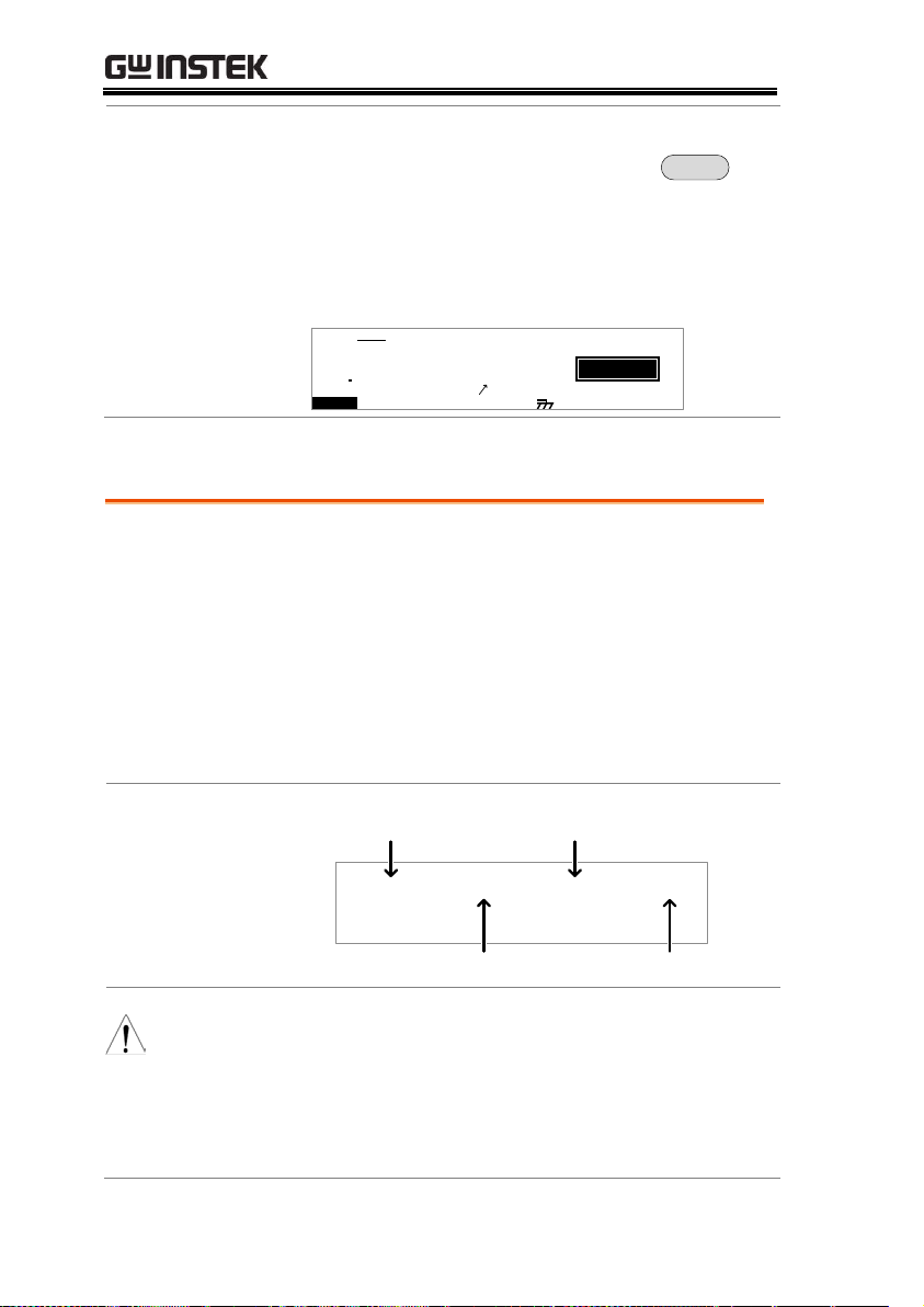
GPT-9000 Series User Manual
Exit Testing
To exit testing, press the
MANU/AUTO key when the
tester is in the READY status. The
tester will revert to the VIEW
status for the current automatic
test.
MANU/AUTO
I R G B A CW D CW
E
F R E Q = 0 H z 6
0
100
k V
EIV
MT I E = 0 0 1 . 0 SR
0 0 m AER F =# 0 .0
1 . 0 0 m AIH ES = 0T
0 0 . 1 S0A MP =R
W
MA U OT N A_0AU T O = 0 0 1 - 1 0
m A
Background
If all the test steps are allowed to run to
completion (the AUTO test is not stopped or a
protection setting is not tripped) then the tester
will judge each step as either PASS or FAIL.
This is shown as a table after the automatic test
has finished running. If the test has been
stopped, then any remaining tests will not be
run and thus the AUTO test will not finish
running.
Overview
P A S
P A SSS
P A S
S K ISP
E MA U OT N A_ 1A U T O = 0 0 1 - 0 0
# 0 1 : # 0 2 : # 0 3 : # 0 4 : P A S
# 0 5 : # 0 6 : # 0 7 : # 0 8 : S T O
# 0 9 : # 1 0 : # 1 1 : # 1 2 :
# 1 3 : # 1 4 : # 1 5 : # 1 6 :
S
P
F A I
F A ILL
FAIL judgmentPASS judgment
skipped step step stopped
Note
The PASS/FAIL judgment for an automatic test
as a whole depends on the results of all the
steps (manual tests) that compose the automatic
test:
Each step must be passed for a PASS judgment
Automatic Test Results
92
Page 93

OPERATION
(excluding skipped tests).
A FAIL result for a single step will result in
FAIL for the whole automatic test.
A STOP. No step can be stopped for a
PASS/FAIL judgment to be made. In other
words, if a test is stopped, it is judged as neither
PASS nor FAIL.
No step can contain an ERROR or ILOCK
message.
E R R
O
P A S
S
E MA U OT N A_ 1A U T O = 0 0 1 - 0 0
# 0 1 : # 0 2 : # 0 3 : # 0 4 : P A S
S
I L O
C
ILOCK messageERROR message
R K
ERROR: Indicates that V, I or R is not correct.
This usually occurs if the testing leads are not
properly connected.
ILOCK: Indicates that the interlock key is
disconnected (if configured to be used).
PASS Judgment
When all the tests have been
judged as PASS, the PASS
indicator will be lit green and the
buzzer will sound.
PASS
P A S
P A SSS
P A S
P A SSS
E MA U OT N A_ *A U TO = 0 0 1 - * *
# 0 1 : # 0 2 : # 0 3 : # 0 4 : P A S
# 0 5 : # 0 6 : # 0 7 : # 0 8 : P A S
# 0 9 : # 1 0 : # 1 1 : # 1 2 :
# 1 3 : # 1 4 : # 1 5 : # 1 6 :
S
S
P A S
P A SSS
Note
The Pass Sound setting must to set to ON for the
buzzer to sound (page 97).
FAIL Judgment
When any of the tests have been
judged as FAIL, the FAIL indicator
will be lit red and the buzzer will
sound.
FAIL
93
Page 94

GPT-9000 Series User Manual
P A S
P A SSS
P A S
F A ISL
E MA U OT N A_ *A U TO = 0 0 1 - * *
# 0 1 : # 0 2 : # 0 3 : # 0 4 : P A S
# 0 5 : # 0 6 : # 0 7 : # 0 8 : P A S
# 0 9 : # 1 0 : # 1 1 : # 1 2 :
# 1 3 : # 1 4 : # 1 5 : # 1 6 :
S
S
P A S
F A ISL
Note
The Fail Sound setting must to set to ON for the
buzzer to sound (page 97).
View Results
1. When the PASS or FAIL overview
table is shown on the screen, turn
the scroll wheel right to scroll
through each test step.
I R G B A CW D C W
F R EQ = 0 H z 6
0
100
k V
SAP
MT I E = 0 0 3 . 2 SR
0 0 m AER F =# 0 .0
1 . 0 0 m AIH ES = 0T
0 0 . 0 S0A M P =R
S
00 37
m A
E MM A UN N A_ 3S T E P : 0 2 - 0 0
PASS/FAIL result
step number
MANU number for
current step
2. Turn the scroll wheel left to return
back to the overview table.
Return to Ready
Status
1. The PASS/FAIL results will be
held on the screen until the STOP
button is pressed.
2. To put the tester back into READY
status, press the STOP button
(twice for a fail result).
STOP
3. The READY indicator will be lit
blue in the READY status.
READY
94
Page 95

OPERATION
I R G B A CW D CW
E
F R E Q = 0 H z 6
0
100
k V
AER
MT I E = 0 0 1 . 0 SR
0 0 m AER F =# 0 .0
1 . 0 0 m AIH ES = 0T
0 0 . 1 S0AM P =R
Y
READY status
MA U OT N A_0A U T O = 0 0 1 - 1 0
D
m A
Exit Testing
To exit testing, press the
MANU/AUTO key when the
tester is in the READY status. The
tester will revert to The VIEW
status.
MANU/AUTO
I R G B A CW D CW
E
F R E Q = 0 H z 6
0
100
k V
EIV
MT I E = 0 0 1 . 0 SR
0 0 m AER F =# 0 .0
1 . 0 0 m AIH ES = 0T
0 0 . 1 S0A MP =R
W
MA U OT N A_0AU T O = 0 0 1 - 1 0
m A
PASS Timing
Diagram
Output V
time
START
TEST
PASS
step 1 ~ step 16
FAIL Timing
Diagram
Output V
time
START
TEST
FAIL
step 1 ~ step 16
95
Page 96

GPT-9000 Series User Manual
Description
The LCD settings include contrast and
brightness controls.
Steps
1. Ensure the tester is in VIEW status.
Save the current test if necessary.
Page 61
I R G B
E
A CW D CW
F R E Q = 0 H z 6
0
100
k V
EIV
MT I E = 0 0 1 . 0 SR
0 0 m AER F =# 0 .0
1 . 0 0 m AIH ES = 0T
0 0 . 1 S0AM P =R
W
MM A UN N A_0M A N U = * * * - 0 0
m A
VIEW status
2. Press the UTILITY key.
UTILITY
3. Press the LCD soft-key to bring up
the LCD Common Utility menu.
L C D
L C D C o t r an
L C D B r g h ti
n se
L C D B U Z Z N T EI R C T R L
s : B R I G H T
s t : 5
MOC MO U N T I L I T Y
Common Utility Settings
The Common Utility settings are system-wide settings that apply to
both MANU tests and AUTO tests.
The Common Utility menu includes the following settings:
LCD settings → from page 96.
Buzzer Settings → from page 97.
Interface Settings → from page 98.
Control settings → from page 100.
LCD Settings
96
Page 97

4. Use the UP/DOWN arrow keys to
choose a menu item: LCD
Contrast, LCD Brightness.
5. Use the scroll wheel to select a
parameter for the chosen menu
item.
LCD Contrast
LCD Brightness
1(low) ~ 8(high)
BRIGHT, DARK
6. Press EDIT/SAVE to save the
settings and exit to VIEW status.
EDIT/SAVE
Note
The ESC key can be pressed at any time to cancel
and exit back to VIEW status.
Buzzer Settings
Description
The Buzzer settings allow you to set whether
the buzzer will sound for PASS/FAIL
judgments. The buzzer time can also be set for
the PASS/FAIL judgments. The buzzer settings
are system-wide.
Steps
1. Ensure the tester is in VIEW status.
Save the current test if necessary.
Page 61
I R G B
E
A CW D CW
F R E Q = 0 H z 6
0
100
k V
EIV
MT I E = 0 0 1 . 0 SR
0 0 m AER F =# 0 .0
1 . 0 0 m AIH ES = 0T
0 0 . 1 S0AM P =R
W
MM A UN N A_0M A NU = * * * - 0 0
m A
VIEW status
2. Press the UTILITY key.
UTILITY
OPERATION
97
Page 98

GPT-9000 Series User Manual
3. Press the BUZZ soft-key to bring
up the Buzzer Common Utility
menu.
B U Z Z
L C D B U Z Z N T EI R C T R L
MOC MO U N T I L I T Y
P a s s S u n do
: NO
F a i l S u n do
: FO F
T I M E : 0 0 . 50
S
4. Use the UP/DOWN arrow keys to
choose a menu item: Pass Sound or
Fail Sound.
5. Use the scroll wheel to select a
parameter for the chosen menu
item.
Pass Sound
Fail Sound
ON (000.2s~999.9s), OFF
ON (000.2s~999.9s), OFF
6. Press EDIT/SAVE to save the
settings and exit to the VIEW
status.
EDIT/SAVE
Note
When in automatic tests, the Pass Sound and Fail
Sound settings only apply to the overall PASS/FAIL
of the
overall automatic test
, not each test step
that make up the automatic tests.
Note
The ESC key can be pressed at any time to cancel
and exit back to VIEW status.
Description
The interface settings choose the remote
interface configuration. USB, RS232 and GPIB
(optional) can be selected.
Interface Settings
98
Page 99

OPERATION
Steps
1. Ensure the tester is in VIEW status.
Save the current test if necessary.
Page 61
I R G B
E
A CW D CW
F R E Q = 0 H z 6
0
100
k V
EIV
MT I E = 0 0 1 . 0 SR
0 0 m AER F =# 0 .0
1 . 0 0 m AIH ES = 0T
0 0 . 1 S0AM P =R
W
MM A UN N A_0M A NU = * * * - 0 0
m A
VIEW status
2. Press the UTILITY key.
UTILITY
3. Press the INTER soft-key to bring
up the Interface Common Utility
menu.
N T EI R
I n t
L C D B U Z Z N T EI R C T R L
MOC MO U N T I L I T Y
B u d :a 1 1 5 2 0 0
R S 2 3 2f a c :e
e r
4. Use the scroll wheel to select USB,
RS232 or GPIB.
5. For RS232 or GPIB, use the
UP/DOWN arrow keys to choose
Baud or Address.
6. Use the scroll wheel to select the
baud rate or GPIB address.
Baud
GPIB address
9600, 19200, 38400, 57600,
115200
0~30
99
Page 100

GPT-9000 Series User Manual
7. Press EDIT/SAVE to save the
settings and exit to VIEW status.
EDIT/SAVE
Note
Ensure the baud rate settings or GPIB address
matches the host machine.
Note
The ESC key can be pressed at any time to cancel
and exit back to VIEW status.
Description
The Control settings are accessed in the
COMMON UTILITY menu. The Control
settings include: Start Control, Double Action,
Key Lock and Interlock.
Start Control is used to determine how a test is
started. Tests can be started via the front panel
(START/STOP buttons), from a remote
controller or via the SIGNAL I/O port.
The Double Action function is a safety feature
used to prevent accidentally starting a test.
Normally to start a test, the START button is
pressed when the tester is in the READY status.
To start a test when Double Action is ON, the
STOP button must first be pressed, followed by
the START button within 500ms.
Key Lock disables the front panel keys from
changing the test number, mode or testing
parameters. Only the Utility menu and any
keys required for testing are not disabled.
Control Settings
100
 Loading...