

Page 1
99 Washington Street
Melrose, MA 02176
Phone 781-665-1400
Toll Free 1-800-517-8431
Visit us at www.TestEquipmentDepot.com
Page 2
Please read this instruction manual before using the
meterandkeepitproperlyforcontingentuse.
PRECAUTION:
Toavoiddangeranddamagehappenedduringoperation,
thefollowingsymbolsareusedaspointsforattention.
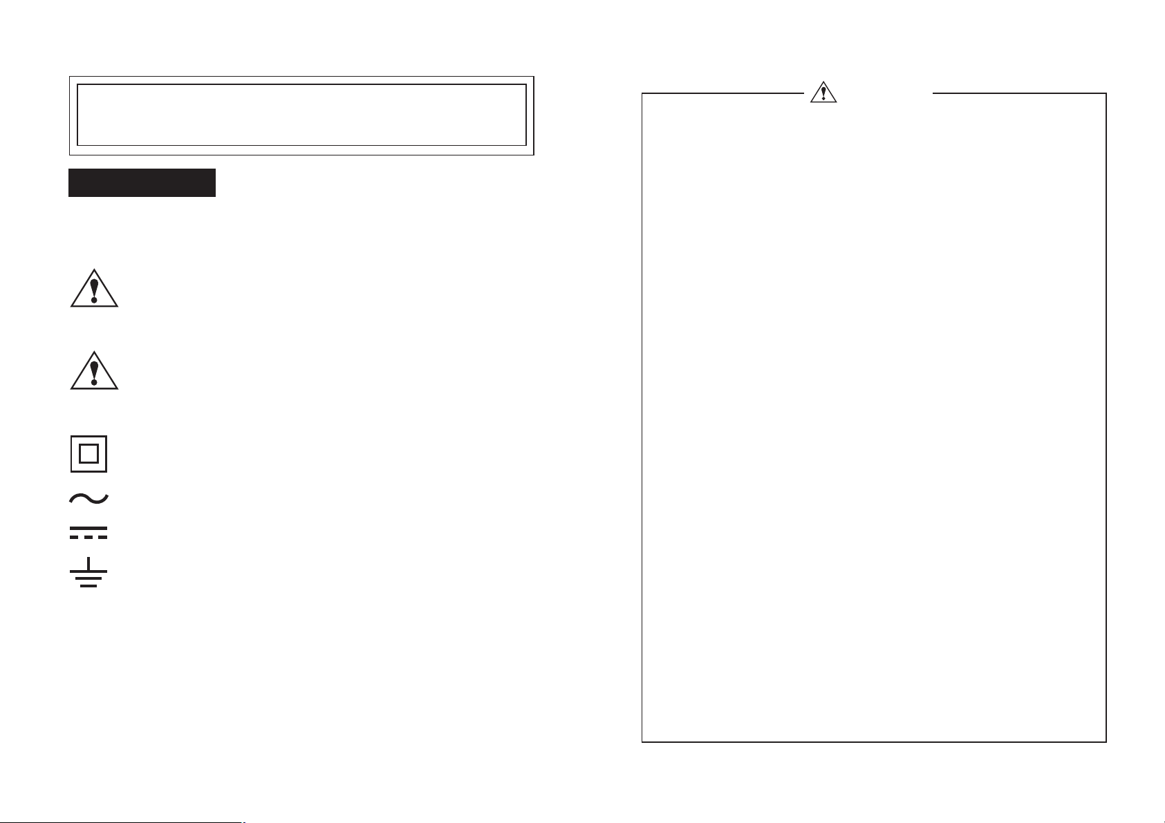
:Warning:
Improper use of the meter may bring
hurt or even death to body. Please
readtheoperationcarefully.
:Caution:
Improper use of the meter may bring
hurt or even death to body. Please
readtheoperationcarefully.
:Dual insulation
:AC - (Alternating Current) voltage / current
:DC - (Direct Current) voltage
:Grounding - Earth Terminal
Warning
To prevent electricalshock or fire!
4
Beforemeasurement, makesurethatthetestleads
1
andfunctionswitchhasbeensetproperly.
Beforeswitchingamong functions, remove the test
1
leadsoffthemeasuredobject.
Beforemeasurement,makesure the circuit current
1
ofobjectwon'texceedthemaximummeasurement
range.
1
Do not use this meter if any crack or damage
occurredinthecaseortestleads.
1
Do not open the case of meter or the battery lib
duringmeasurement.
1
Please keep your hands behind the guard ring of
testleadswhilemeasuringwithtestleads.
1
Pleasekeepyourhands below the guard ringofthe
meterwhilemeasuringwithsensoringjaw.
1
Before proceeding resistance measurement, turn
offthepowertothecircuitundertestfirst.
1
Never use the meter in rainyor humid environment
orwithwethands.
1
Before proceeding current measurement, make
sure to remove the test leads from the input
terminals.
-1- -2-
Page 3
Warning
To prevent damage to the meter or electrical
4
shock!
According to the safety standard, the maximum voltage
input power is classified as follows to protect the users
against transient impulse voltage in power lines.
Over-voltageCategory (CAT.) Maximuminputvoltage
CATII 600V
Caution
1
Do not use the meter near equipment emitting noise or
under an environment with sudden temperature
change; otherwise, unstable or erroneous reading will
appear.
1
Take the batteries out of the meter ifit will be left idle for
along time.
1
After measurement, switch the function knob back to
OFFposition. Asthere will be slight power consumption
underauto poweroffmode.
1
Please position the conductor in the center of jaw in
order to ensure the accuracy of measurement while
measuring current.
1
Please make sure to keep out of high current to ensure
the accuracy of measurement while measuring
current.
1
Donotuse organic solvent tocleanthe meter but with a
softcloth ifnecessary.
1
Do not expose the meter under direct sunshine or
extreme temperature or in moisture places.
1
When the measurement values appear irregularly
or the symbol displays, replace the batteries
immediately to ensure normal operation.
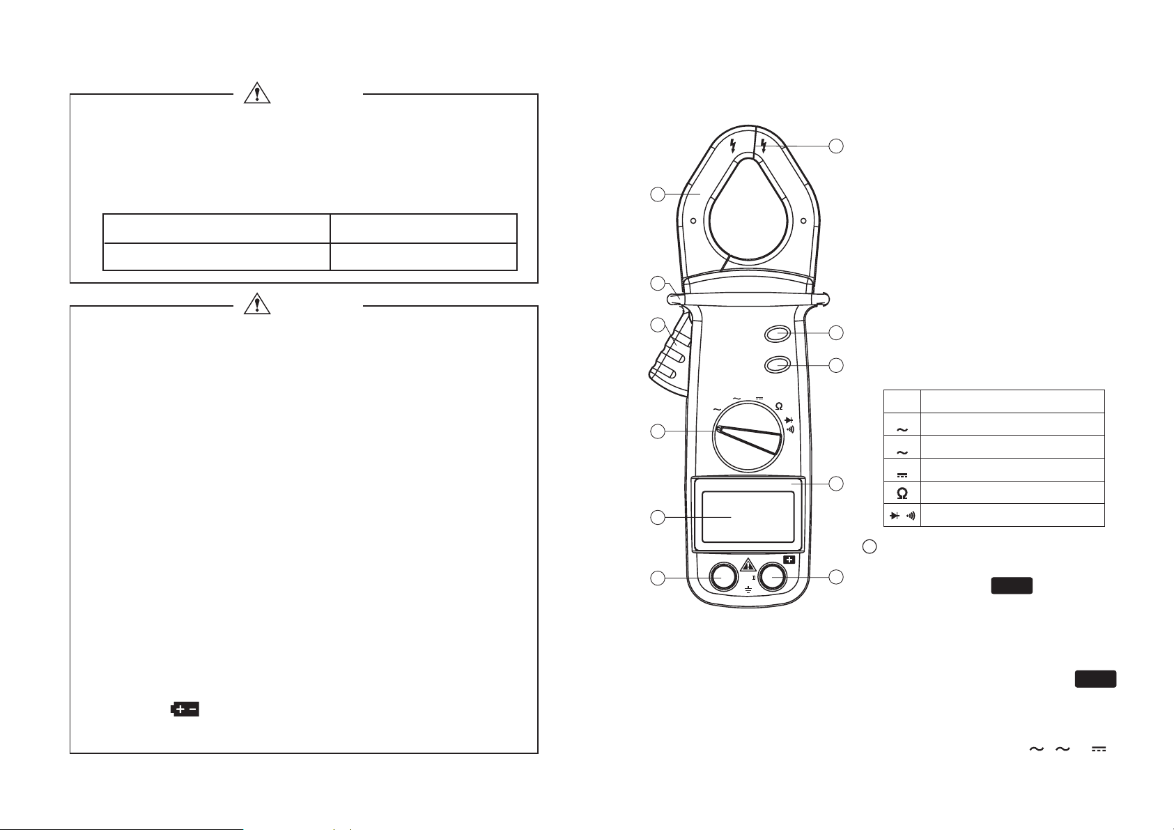
( 1 ) NAME OF PARTS
j
2
1
k
l
3
10
4
AC
CLAMP METER
AUTO RANGE
A
OFF
5
9
COM
MAX
SELECT
V
V
CAT
600V
11
m
6
7
n
8
6
Jaw
Position the conductor in the
center of jaw in order to ensure
the accuracy of reading while
measuringcurrent.
Opening of the jaw
Guard ring
Keep your hands below the
guard ring of the meter while
measuringwith sensoring jaw.
Clamp trigger
Press down the trigger to open
the jaw.
Function switch knob
OFF
Turnoff the power
A
AC current measurement
V
AC voltage measurement
V
DC voltage measurement
Resistance measurement
Diode / Continuity check
/
MAX key
Press MAX key during
measurement, symbol will
MAX
appear on the LCD; and the
maximum value will be locked
and renewed instantaneously.
To cancel this function, just
press MAX key again and
ymbol will disappear.
s
Note:
This function is only
applicable to , &
A V
MAX
V
-3-
-4-
Page 4
7
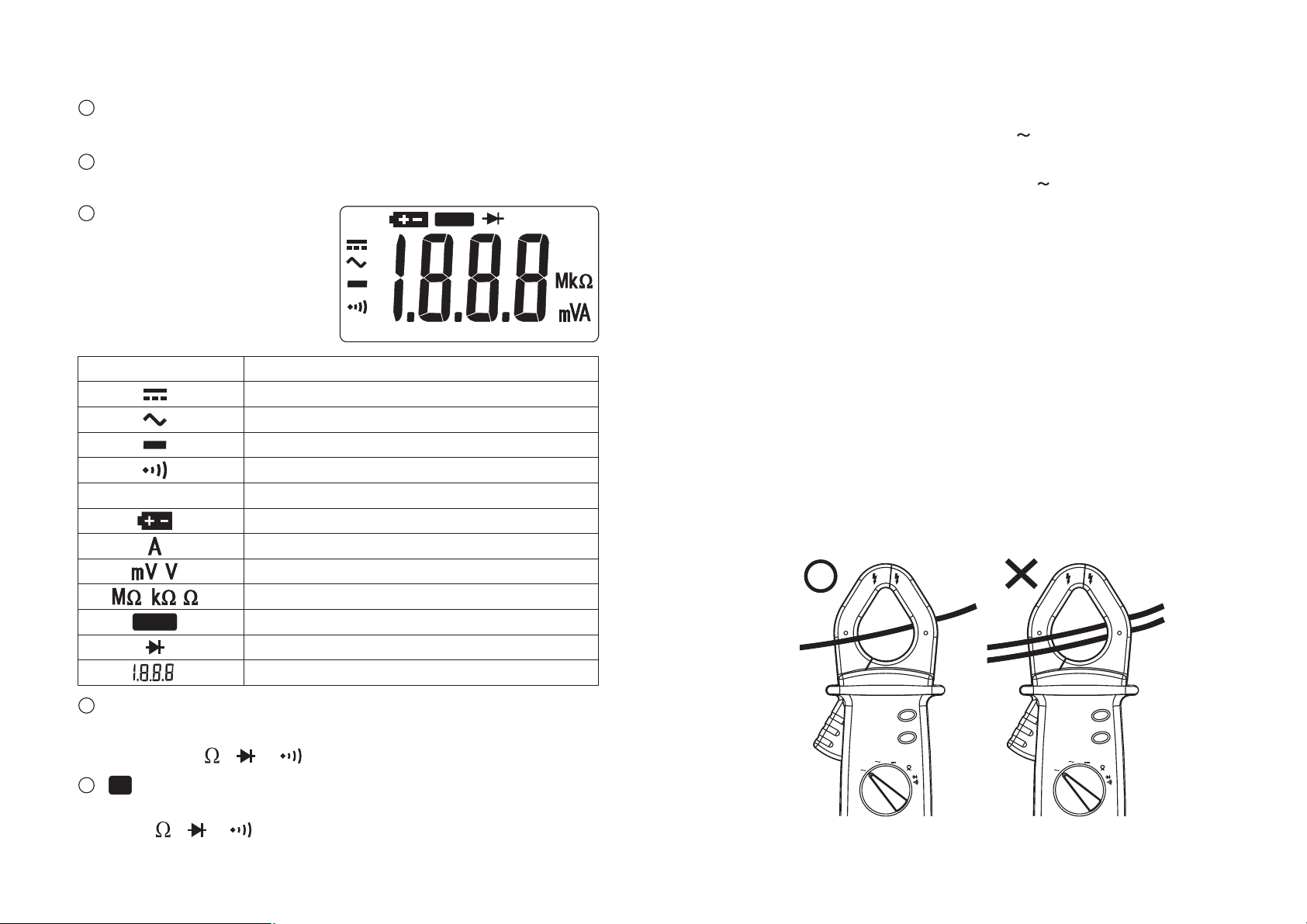
SELECT key
Transform between diode and continuity check.
8
Name plate
Mark product brand and model number
9
LCD Display
MAX
Show measurement
symbols, units and values
AUTO
(2) MEASURING INSTRUCTIONS
n AC Current Measurement ( )
Measuring range: 200A~600A (2 ranges, auto-ranging)
1.Set the function switch knob on
2.Press down the clamp trigger to open the jaw, place one
conductor in the center of the jaw (as below drawing),
then read the value when it stabilizes.
Note:
3.The meter will choose the appropriate range to measure
Please put the conductor in the center of jaw in
order to avoid serious inaccuracy
A
A
Symbols / Units Description
Lit when in DC mode measurement
Lit when in AC mode measurement
Negative polarity indicator
Lit when in continuity check
AUTO
Auto-ranging indicator
Low battery indicator
Unit for current measurement
,
,,
MAX
Unit for voltage measurement
Unit for resistance measurement
Maximum value lock indicator
Lit when in diode measurement
Measured value display
10
COM Terminal
For connecting the negative input end (black test lead) for
DCV, ACV,
11
+
terminal
&
,
measurement
For connecting the positive input end (red test lead) for DCV,
ACV,
&
,
measurement
automatically.
4.When measurement finished, set the function switch
knob OFF position to turn off the meter.
on
Note:
If the measurement is conducted in a place with dim
light, you may press MAX key to lock the value
measured and read it in other places with proper
illumination.
MAX
AC AC
CLAMPMETER
AUTO RANGE
SELECT
V
V
A
OFF
-6--5-
OFF
CLAMPMETER
AUTO RANGE
V
A
SELECT
V
MAX
Page 5
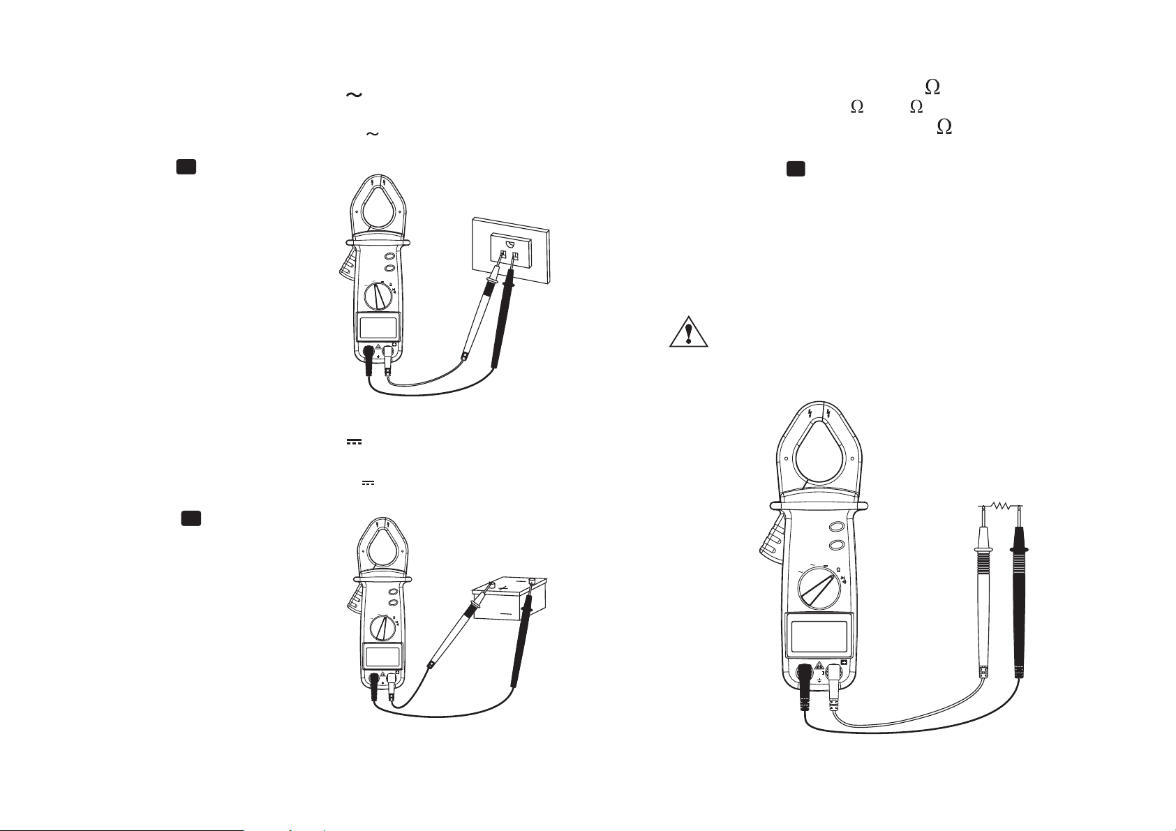
nnAC Voltage Measurement ( )
V
Measuring range: 2V-600V(4 ranges, auto-ranging)
1.Set the function switch knob on
V
2.Plug the black test lead into COM terminal and the red
one into terminal
+
3.Connect the test leads to the
cir uitunder test and then
c
read the value when
it stabilizes
4.The meter will choose
the appropriate range to
AC
CLAMPMETER
AUTO RANGE
OFF
MAX
SELECT
V
V
A
measure automatically
5.When measurement finished,
set the function switch knob
n OFF position to turn off
o
he meter.
t
COM
600V
n Resistance Measurement ( )
Measuring range: 200 -20M (6ranges, auto-ranging)
1.Set the function switch knob on
2.Plug the black test lead into COM terminal and the
red one into terminal
3.Connect the test leads to the circuit under test and
then read the value when it stabilizes
4.The meter will choose the appropriate range to
measure automatically
5.When measurement finished, set the function switch
knob on OFF position to turn off the meter.
: Before undergoing resistance measurement,
firstly switch offthe power to the circuit under
test and fully discharge the capacitor.
+
DC Voltage Measurement ( )
V
Measuring range: 200mV-600V(5 ranges, auto-ranging)
1.Set the function switch knob on
V
2.Plug the black test lead into COM terminal and the red
one into terminal
+
3.Connect the test leads to the
circuit under test and then
read the value when it
MAX
AC
stabilizes
4.The meter will choose the
CLAMPMETER
AUTO RANGE
OFF
SELECT
V
V
A
12
V
appropriate range to measure
utomatically
a
6.When measurement finished,
COM
600V
set the function switch knob on
OFF position to turn off the meter.
-7- -8-
AC
CLAMPMETER
AUTO RANGE
A
OFF
COM
MAX
SELECT
V
V
CAT
600V
Page 6
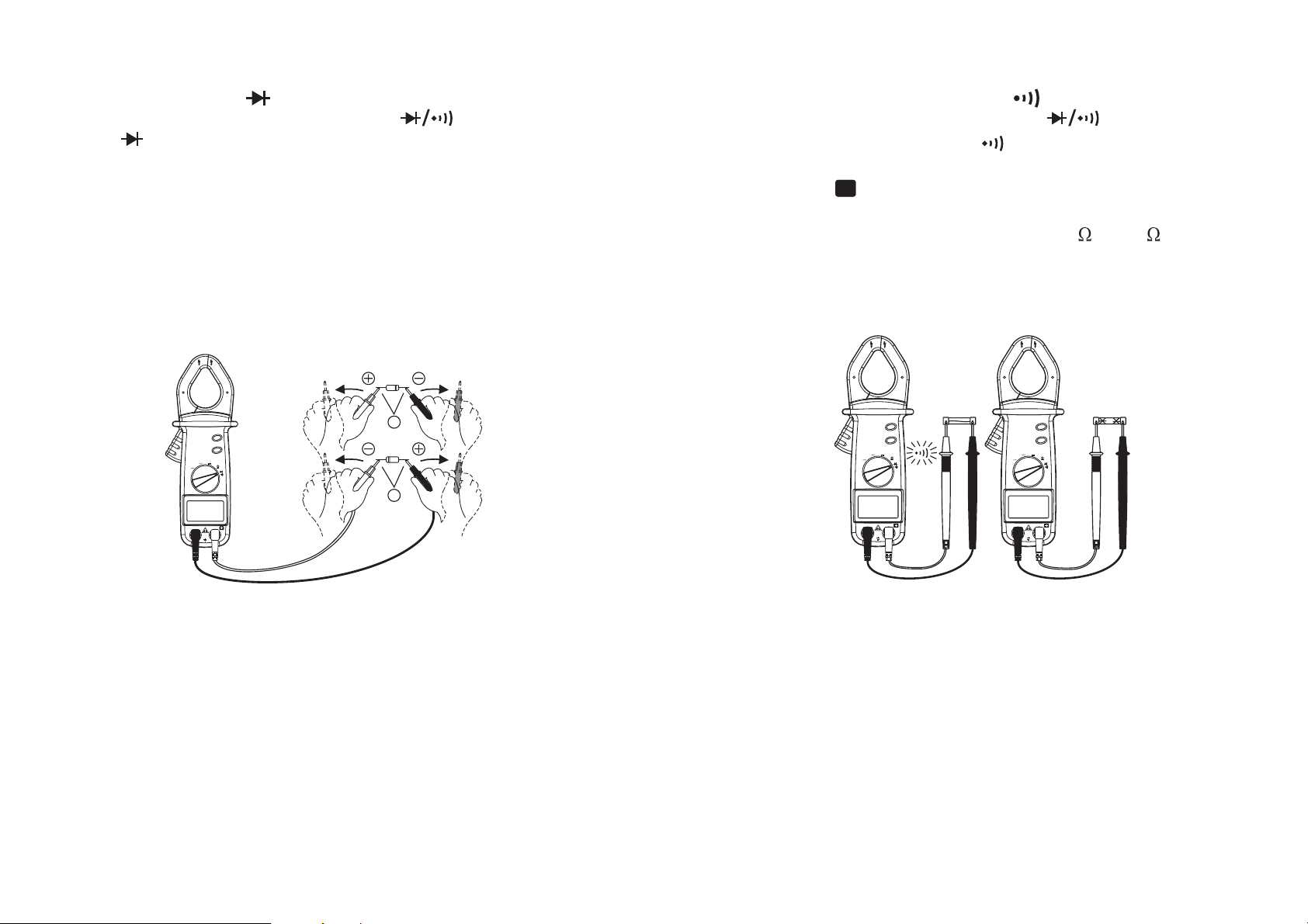
n Diode Check ( )
1.Set the function switch knob on
2. Symbolwillappear on the LCD
3.Connect the test leads to the diode and then read the
value when it stabilizes
(A)Forward-bias Diode Test
Connect black test lead to the cathode and red one to
the anode
Silicon diode value reading approximate 0.5~0.7V
Germanium diode value reading approximate 0.5~0.7V
Note that reading close to 0V represents a shortcircuit and "OL" symbol indicates an open-circuit.
Red testing lead
n Continuity Measurement ( )
1.Set the function switch knob on
2.Press SELECT key until symbolappears on LCD
3.Plug the black test lead into COM terminal and the red
one into terminal
4.Connect the test leads to the circuit under test. If
circuit is continuous or less than 60 (
beeper will sound
5.When measurement finished, set the function switch
knob on OFF position to turn off the meter.
+
_
+
20 ),the
A
MAX
AC
CLAMPMETER
AUTO RANGE
SELECT
V
V
A
OFF
B
COM
600V
Black testing lead
(B)Reverse-biasDiode Test
Connect black test lead to the anode and red one to
the cathode. Normally, it shows OL on display,
indicating that the diode under test is normal. The
diode is defective if the display gives a certain
voltage level.
4.When measurement finished, set the function
knob
on OFF position to turn off the meter.
-9- -10-
switch
AC
CLAMPMETER
AUTO RANGE
A
OFF
COM
MAX
SELECT
V
V
600V
AC
CLAMPMETER
AUTO RANGE
OFF
COM
MAX
SELECT
V
V
A
600V
(3) AUTO POWER OFF (POWER-SAVING)DEVICE
When power on the meter and you don't touch any key
or function switch knob for 15 minutes, the meter will
turn the power off automatically. One minute before
the meter shut down, the alarm sounds to warn the
users. Once the meter turns the power off already,you
can press the MAX key to regenerate the meter again.
Page 7
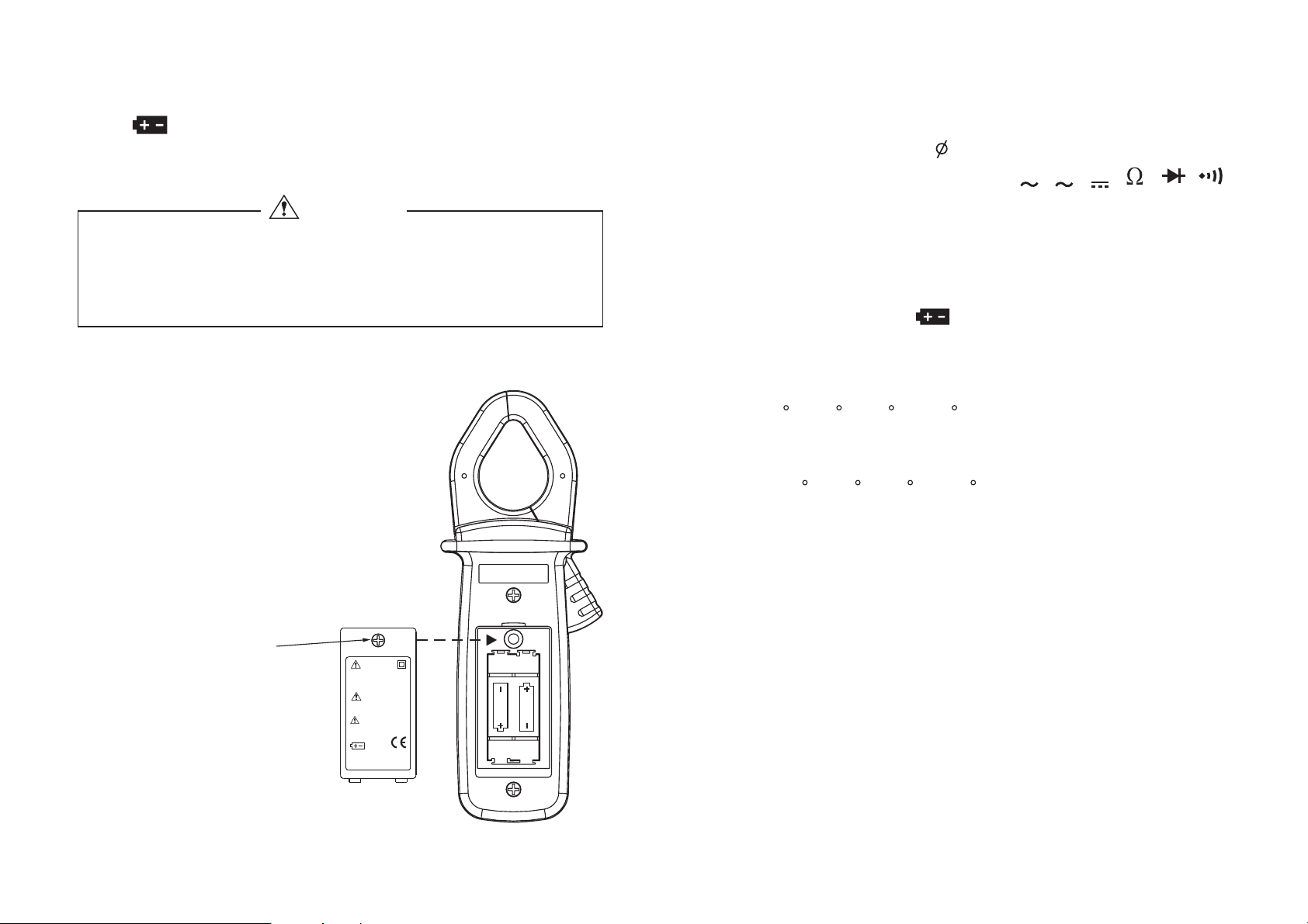
(4) Replacing Batteries
If symbols appears, the batteries fall below the normal
operation voltage. Replace them with 2 new batteries.
(Standard UM-4 or R03 AAA batteries)
CAUTION
l
Before replacing batteries, make sure to disconnect
the clamp meter from the circuit under test.
l
Replace two new batteries at the same time, and make
sure you put the batteries at correct polarities.
(5) Battery Replacement Steps
1.Abort the measuring action
2.Turn the function switch knob
back to OFF
3.Remove the screw on the back of
casing (as drawing)
4.Open the battery lid
5.Load the new batteries
6.Install the battery lid into the casing
a
nd fasten it with the screw
Remove the screw
on the back of casing
WARNING
TOAVOID ELECTRICAL
SHOCK, REMOVETEST
LEADS BEFORE
OPENING CASE.
DANGER
DO NOTUSE ONBARE
CONDUCTORS.
PLEASE READ
MANUAL FOR SAFETY
BEFORE USING.
USE BATTERY 1.5VX2
AAA SIZE
1.5V
SIZE "AAA"
(6) Specification
1. General Specification:
l
Max Clamp Size:
l
Measurement Functions:
l
Additional Functions:
l
LCD Display:
Unit & function indication, 1999 digits as maximum
reading, negative polarity indicator,overload
indicator ( "OL" indicating overload of resistance,
beeper,diode), indicating low battery.
Range:
l
Sampling Rate:
l
Operation Temperature/Humidity:
l
Auto-ranging
0 C~50 C (32 F~122 F) / below 80% R.H.
(no condensation)
Storage Temperature/Humidity:
l
-10 C~60 C (14 F~140 F) / below 70% R.H.
o condensation)
(n
Power Supply:
l
batteries
Battery Life:
l
Alkaline batteries approx. 400 hours
General batteries approx. 240 hours
Dimensions:
l
Weight:
l
1.5V
SIZE "AAA"
approx. 200g (batteries included)
189mm(L) x 71mm(W) x 37mm(H)
30mm or 10x35mm
,,,
,,
V
V
A
Max hold, auto power off
approx. 3 times per second
2 pcs of standard UM-4 or R03AAA
Battery lid
-11- -12-
Page 8
l
Comply
l
Accessories:
with
Safety Standard:
AAA 1.5V ..............2 (inside the case)
Test leads.......................................1
Instruction manual ..........................1
Carrying case.................................1
l
Optional Accessories:
AC Line Splitter
(Direct measuring with nonecessityto
split the wire awaybynegative and positive
independently. Hence, it also can amplify
he small current by10times for easy reading)t
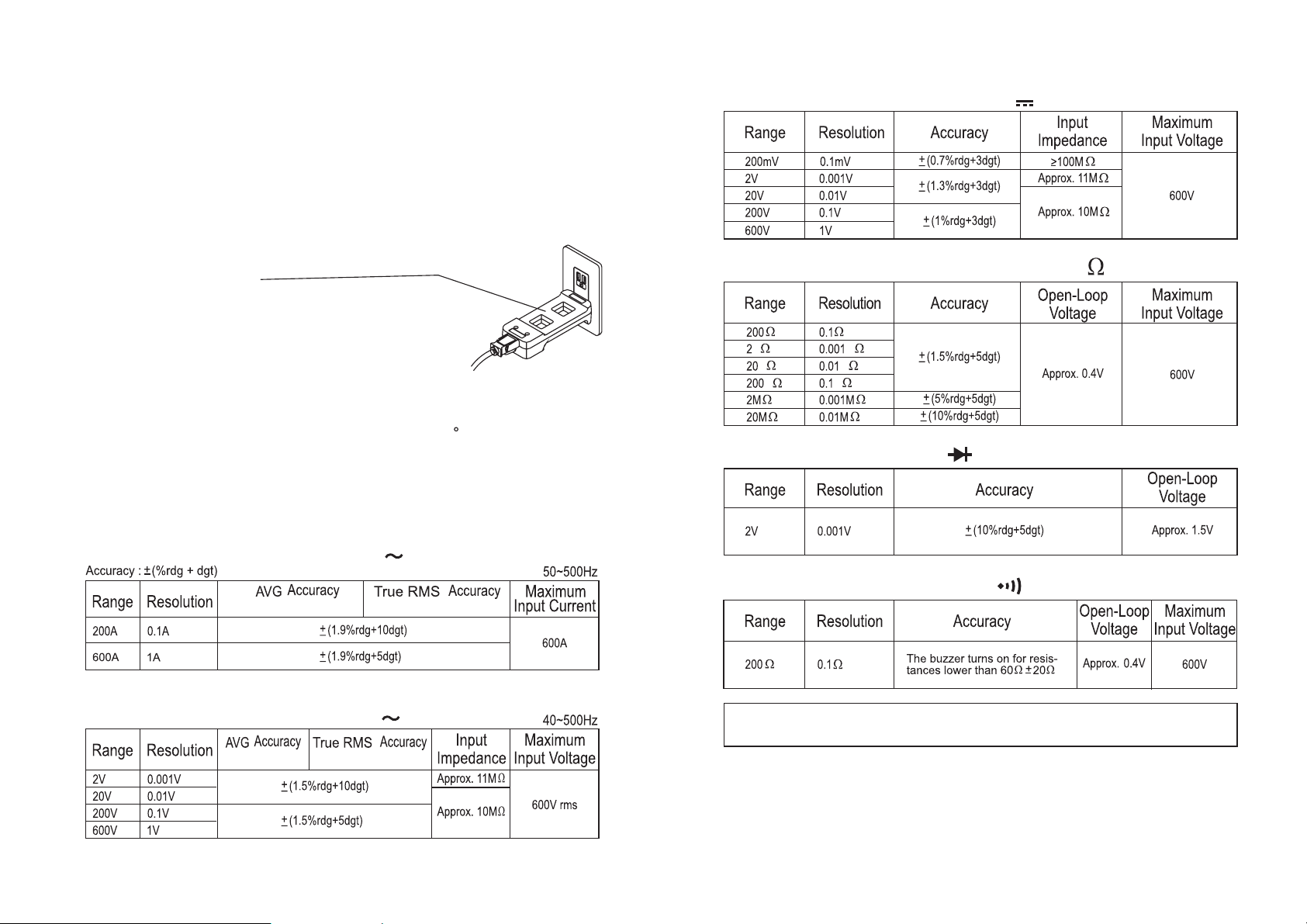
2. Electrical Specification:
Environment temperature/ humidity:
rdg: reading digits
dgt: decimal digits
IEC 61010-1 600V CAT
Pollution degree 2
X1
X10
_
+
23
5 C/ below 80% R.H.
ll
n DCV measurement (set on )
V
n Resistance measurement (set on )
k
k
k
k
k
k
n Diode check (set on )
n
ACA measurement (set on )
GCM-302
n
ACV measurement (set on )
GCM-302
GCM-303
-13- -14-
A
GCM-303
V
n Continuity check (set on )
Specification and outward appearance of the product described above may be
revised for modification without prior notice.
 Loading...