

Page 1
Arbitrary Function Generator
AFG-3021, 3022, 3031 & AFG-3032
USER MANUAL
GW INSTEK PART NO. 82FG-30320E01
ISO-9001 CERTIFIED MANUFACTURER
99 Washington Street
Melrose, MA 02176
Phone 781-665-1400
Toll Free 1-800-517-8431
Visit us at www.TestEquipmentDepot.com
Page 2

February 2016 edition
This manual contains proprietary information, which is protected by
copyright. All rights are reserved. No part of this manual may be
photocopied, reproduced or translated to another language without
prior written consent of Good Will Corporation.
The information in this manual was correct at the time of printing.
However, Good Will continues to improve its products and therefore
reserves the right to change the specifications, equipment, and
maintenance procedures at any time without notice.
Good Will Instrument Co., Ltd.
No. 7-1, Jhongsing Rd., Tucheng City, Taipei County 236, Taiwan.
Page 3

TABLE OF CONTENTS
Table of Contents
SAFETY INSTRUCTIONS .................................. 6
GETTING STARTED ........................................ 12
Main Features ................................................................... 12
Panel Overview .................................................................. 15
Setting up the Function Generator .................................... 24
QUICK REFERENCE ....................................... 26
How to use the Digital Inputs ........................................... 28
How to use the Help Menu ............................................... 29
Selecting a Waveform ........................................................ 32
Modulation ........................................................................ 36
Sweep ................................................................................ 42
Burst ................................................................................. 43
ARB ................................................................................... 44
Utility Menu ...................................................................... 48
Menu Tree ......................................................................... 51
Default Settings ................................................................ 68
OPERATION ................................................... 70
Select a Channel ................................................................ 71
Select a Waveform ............................................................. 72
MODULATION ............................................... 89
Amplitude Modulation (AM) ............................................. 91
Frequency Modulation (FM) ............................................ 100
Frequency Shift Keying (FSK) Modulation ........................ 108
Phase Modulation (PM) .................................................. 115
SUM Modulation ............................................................. 121
Pulse Width Modulation .................................................. 128
Sweep .............................................................................. 135
3
Page 4

AFG-3021/3022/3031/3032 User Manual
Burst Mode ..................................................................... 146
SECONDARY SYSTEM FUNCTION SETTINGS
..................................................................... 158
Save, Recall or Delete ...................................................... 159
Selecting the Remote Interface ........................................ 163
System and Settings ........................................................ 168
DUAL CHANNEL & MULTI-UNIT OPERATION
..................................................................... 177
Dual Channe l Settings ..................................................... 178
Multi-Unit Syncing .......................................................... 186
ARBITRARY WAVEFORMS ............................ 190
Inserting Built-In Waveforms ........................................... 191
Display an Arbitrary Waveform ........................................ 198
Editing an Arbitrary Waveform ......................................... 205
Output an Arbitrary Waveform ......................................... 214
Saving/Loading an Arbitrary Waveform ............................ 221
REMOTE INTERFACE ................................... 229
Establishing a Remote Connection .................................. 230
Web Browser Control Interface ........................................ 237
Command Syntax ............................................................. 240
Command List ................................................................. 245
488.2 Common Commands .............................................. 251
Status Register Commands .............................................. 254
System Commands .......................................................... 260
Apply Commands ............................................................ 263
Output Commands .......................................................... 271
Pulse Configuration Commands ...................................... 281
Harmonic Commands ...................................................... 284
Amplitude Modulation (AM) Commands ......................... 288
AM Overview ................................................................... 288
4
Page 5

TABLE OF CONTENTS
Frequency Modulation (FM) Commands ......................... 293
FM Overview ................................................................... 293
Frequency-Shift Keying (FSK) Commands ........................ 298
FSK Overview .................................................................. 298
Phase Modulation (PM) Commands ................................ 302
PM Overview ................................................................... 302
Additive Modulation (SUM) Commands .......................... 306
SUM Overview ................................................................. 306
Pulse Width Modulation (PWM) Commands ................... 311
PWM Overview ................................................................ 311
Frequency Sweep Commands .......................................... 316
Sweep Overview .............................................................. 316
Burst Mode Commands ................................................... 327
Burst Mode Overview ...................................................... 327
Arbitrary Waveform Commands ....................................... 337
Arbitrary Waveform Overview .......................................... 337
Tracking Commands ........................................................ 378
Reference Commands ...................................................... 383
Save and Recall Commands ............................................. 384
Error Messages ............................................................... 386
SCPI Status Registers ...................................................... 399
APPENDIX .................................................... 405
Fuse Replacement ........................................................... 405
AFG-3021, AFG-3022, AFG-3031 & AFG-3032 Specifications
........................................................................................ 406
EC Declaration of Conformity .......................................... 413
ARB Built-In Waveforms .................................................. 414
INDEX .......................................................... 422
5
Page 6
AFG-3021/3022/3031/3032 User Manual
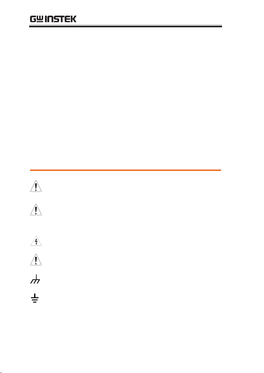
WARNING
Warning: Identifies conditions or practices that
could result in injury or loss of life.
CAUTION
Caution: Identifies conditions or practices that
could result in damage to the function generator or
to other objects or property.
DANGER High Voltage
Attention: Refer to the Manual
Signal ground. Chassis ground
Signal ground. Isolated from other channels and
ground.
SAFETY INSTRUCTIONS
This chapter contains important safety instructions
that should be followed when operating and
storing the function generator. Read the following
before any operation to ensure your safety and to
keep the function generator in the best condition.
Safety Symbols
These safety symbols may appear in this manual or on the
instrument.
6
Page 7

Do not dispose electronic equipment as unsorted
municipal waste. Please use a separate collection
facility or contact the supplier from which this
instrument was purchased.
Safety Guidelines
General
Guideline
CAUTION
Do not place heavy objects on the instrument.
Do not place flammable objects on the
instrument.
Avoid severe impact or rough handling that
may damage the function generator.
Avoid discharges of static electricity on or near
the function generator.
Use only mating connectors, not bare wires, for
the terminals.
The instrument should only be disassembled by
a qualified technician.
Do not apply more than 42Vpk to any
input/output ground or to the chassis ground.
Do not apply voltage to the output terminals to
avoid damage to the instrument.
Do not apply more than ±5V to the trigger or
MOD input terminals to avoid damage to the
instrument.
(Measurement categories) EN 61010-1:2010 specifies the
measurement categories and their requirements as follows. The
AFG-30XX falls under category II.
Measurement category IV is for measurement performed at the
source of a low-voltage installation.
Measurement category III is for measurement performed in a
building installation.
Measurement category II is for measurement performed on
circuits directly connected to a low voltage installation.
Measurement category I is for measurements performed on
circuits not directly connected to Mains.
SAFETY INSTRUCTIONS
7
Page 8
AFG-3021/3022/3031/3032 User Manual
Power Supply
WARNING
AC Input voltage: 100 - 240V AC, 50 - 60Hz.
Connect the protective grounding conductor of
the AC power cord to an earth ground to
prevent electric shock.
Fuse
WARNING
Fuse type:
AFG-3032&3022: T1A/250V
AFG-3031&3021: T0.63A/250V
Only qualified technicians should replace the
fuse.
To ensure fire protection, replace the fuse only
with the specified type and rating.
Disconnect the power cord and all test leads
before replacing the fuse.
Make sure the cause of the fuse blowout is fixed
before replacing the fuse.
Ground
CAUTION
The AFG-30XX is a floating function generator;
the AFG-30XXs’ common ground is electrically
isolated from the chassis ground by a 42Vpk
isolation voltage (DC + peak AC). Exceeding
42Vpp may cause damage to the internal
circuits.
Do not short the chassis ground with
CH1(MAIN)’s or CH2’s common ground if
there is a potential voltage difference between
them. Doing so may damage the unit or
externally connected equipment.
If there is a potential voltage between CH1’s and
CH2’s common ground, do not short them.
Doing so may damage the unit or externally
connected equipment.
WARNING
To avoid electric shock ensure that the output
voltage and floating voltage does not exceed
42Vpk in total.
Do not touch any exposed connectors when the
unit is being operated.
8
Page 9

SAFETY INSTRUCTIONS
Cleaning the
function
generator
Disconnect the power cord before cleaning the
function generator.
Use a soft cloth dampened in a solution of mild
detergent and water. Do not spray any liquid
into the function generator.
Do not use chemicals containing harsh products
such as benzene, toluene, xylene, and acetone.
Operation
Environment
Location: Indoor, no direct sunlight, dust free,
almost non-conductive pollution (Note below)
and avoid strong magnetic fields.
Relative Humidity: < 80%
Altitude: < 2000m
Temperature: 0°C to 40°C
(Pollution Degree) EN 61010-1:2010 specifies pollution degrees and
their requirements as follows. The function generator falls under
degree 2.
Pollution refers to “addition of foreign matter, solid, liquid, or
gaseous (ionized gases), that may produce a reduction of dielectric
strength or surface resistivity”.
Pollution degree 1: No pollution or only dry, non-conductive
pollution occurs. The pollution has no influence.
Pollution degree 2: Normally only non-conductive pollution
occurs. Occasionally, however, a temporary conductivity caused
by condensation must be expected.
Pollution degree 3: Conductive pollution occurs, or dry, non-
conductive pollution occurs which becomes conductive due to
condensation which is expected. In such conditions, equipment
is normally protected against exposure to direct sunlight,
precipitation, and full wind pressure, but neither temperature
nor humidity is controlled.
Storage
environment
Location: Indoor
Relative Humidity: < 70%
Temperature: -10°C to 70°C
9
Page 10

AFG-3021/3022/3031/3032 User Manual
Disposal
Do not dispose this instrument as unsorted
municipal waste. Please use a separate collection
facility or contact the supplier from which this
instrument was purchased. Please make sure
discarded electrical waste is properly recycled to
reduce environmental impact.
Class A Device
WARNING
The AFG-30XX function generators are categorized
as Class A equipment. Class A equipment is
intended for use in an industrial environment.
Class A equipment may have potential difficulties
in ensuring electromagnetic compatibility in other
environments, due to conducted as well as
radiated disturbances.
10
Page 11

SAFETY INSTRUCTIONS
Green/ Yellow:
Earth
Blue:
Neutral
Brown:
Live (Phase)
Power cord for the United Kingdom
When using the function generator in the United Kingdom, make sure the
power cord meets the following safety instructions.
NOTE: This lead/appliance must only be wired by competent persons
WARNING: THIS APPLIANCE MUST BE EARTHED
IMPORTANT: The wires in this lead are coloured in accordance with the
following code:
As the colours of the wires in main leads may not correspond with the
coloured marking identified in your plug/appliance, proceed as follows:
The wire which is coloured Green & Yellow must be connected to the Earth
terminal marked with either the letter E, the earth symbol or coloured
Green/Green & Yellow.
The wire which is coloured Blue must be connected to the terminal which is
marked with the letter N or coloured Blue or Black.
The wire which is coloured Brown must be connected to the terminal
marked with the letter L or P or coloured Brown or Red.
If in doubt, consult the instructions provided with the equipment or contact
the supplier.
This cable/appliance should be protected by a suitably rated and approved
HBC mains fuse: refer to the rating information on the equipment and/or
user instructions for details. As a guide, a cable of 0.75mm2 should be
protected by a 3A or 5A fuse. Larger conductors would normally require
13A types, depending on the connection method used.
Any exposed wiring from a cable, plug or connection that is engaged in a
live socket is extremely hazardous. If a cable or plug is deemed hazardous,
turn off the mains power and remove the cable, any fuses and fuse
assemblies. All hazardous wiring must be immediately destroyed and
replaced in accordance to the above standard.
11
Page 12
AFG-3021/3022/3031/3032 User Manual
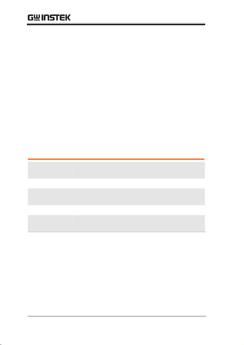
Model name
Frequency
bandwidth
Channels
AFG-3021
20MHz
1(signal ground chassis isolation)
AFG-3022
20MHz
2 (signal ground chassis isolation and
channel isolation)
AFG-3031
30MHz
1(signal ground chassis isolation)
AFG-3032
30MHz
2 (signal ground chassis isolation and
channel isolation)
Performance
DDS Function Generator series
1μHz high frequency resolution maintained at
full range
1ppm frequency stability
Full Function Arbitrary Waveform Capability
-250 MSa/s sample rate
-125 MSa/s repetition rate
-8 M-point waveform length
-16-bit amplitude resolution
GETTING STARTED
The Getting started chapter introduces the
function generator’s main features, appearance, set
up procedure and power-up.
Note: Throughout this manual, “AFG-30XX”
refers to the AFG-3021, AFG-3022, AFG-3031 &
AFG-3032, unless stated otherwise.
Main Features
12
Page 13

-Ten 8 M waveform memories
-True waveform output to display
-User define output section
-D W R (Direct Waveform Reconstruction)
capability
-Waveform editing capability sans PC
-N Cycle and Infinite output mode selectable
-60dBc low distortion sine wave
Features
Sine, Square, Triangle, Pulse, Ramp, Noise, DC
standard waveforms
Int/Ext AM, FM, PWM, FSK, PM, SUM
modulation
Modulation/sweep signal output
Burst function with internal and external
triggers
Store/recall 10 groups of setting memories
Output overload protection
Two channel tracking (AFG-3022/3032 only)
42Vpk signal ground chassis isolation and
42Vpk channel isolation
Multi-unit synchronized control
DSO Link function to transfer captured
waveforms from the DSO to the function
generator
Harmonic waveform function
Pulse waveform with configurable rise times &
fall times
Frequency and amplitude sweep
GETTING STARTED
13
Page 14

AFG-3021/3022/3031/3032 User Manual
Interface
Interface: Standard: LAN, USB Optional: GPIB
4.3 inch color TFT LCD (480 × 272) Graphical
User Interface
AWES (Arbitrary Waveform Editing Software)
PC software
14
Page 15
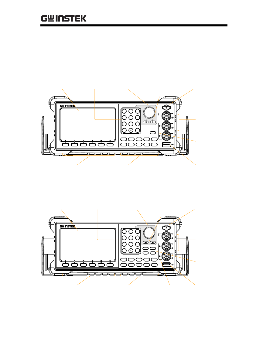
Panel Overview
Arbitrary Function Generator
AFG-3031
OUTPUT
Waveform FREQ/Rate AMPL DC Offset UTIL
Preset
0
7 8 9
4 5 6
1 2 3
/
Output
F 1 F 2
F 3
F 4 F 5 F 6
ARB MOD Sweep Burst
MAIN
50
W
50
W
MOD
SYNC
MAIN
42V
MAX
42V
MAX
42V
MAX
LCD Display Number
pad
Scroll Wheel
Output
Terminals
Function keys USB portOutput
indicators
Output key
Selection
keys
Power Switch
Operation
keys
CH2
CH1
Output
Arbitrary Function Generator
AFG-3032
OUTPUT
Waveform FREQ/Rate AMPL DC Offset UTIL
Preset
0
7 8 9
4 5 6
1 2 3
/
Output
F 1 F 2
F 3
F 4 F 5 F 6
ARB MOD Sweep Burst
CH2
CH1
50
W
50
W
SYNC
CH2
CH1
42V
MAX
W
42V
MAX
42V
MAX
50
LCD Display Number
pad
Scroll Wheel
Output
Terminals
Function keys USB portOutput
indicators
Output
keys
Selection
keys
Power Switch
Operation
keys
CH1/CH2
Front Panel
AFG-3021/3031
AFG-3022/3032
GETTING STARTED
15
Page 16
AFG-3021/3022/3031/3032 User Manual
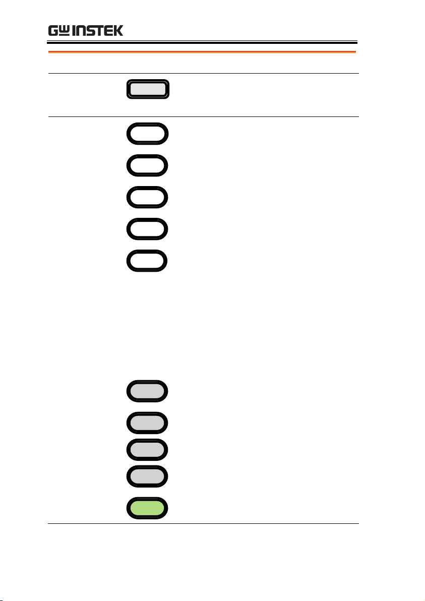
LCD display
TFT color LCD display, 480 x 272 resolution.
Function keys:
F1~F6
F 1
Activates the functions which
appear in the bottom of the LCD
display.
Operation keys
Waveform
Waveform is used to select a
waveform type.
FREQ/Rate
The FREQ/Rate key is used to set
the frequency or sample rate.
AMPL
AMPL sets the waveform
amplitude.
DC Offset
Sets the DC offset.
UTIL
The UTIL key is used to access the
save and recall options, set the
remote interface (USB, GPIB,
LAN), use DSO link (AFG3021/3031), update and view the
firmware version, access the
calibration options, output
impedance settings (AFG3021/3031 only), set the language
and access the help menu.
ARB
ARB is used to set the arbitrary
waveform parameters.
MOD
Sweep
Burst
The MOD, Sweep and Burst keys
are used to set the modulation,
sweep and burst settings and
parameters.
Preset
Preset
The preset key is used to recall a
preset state.
16
Page 17
GETTING STARTED
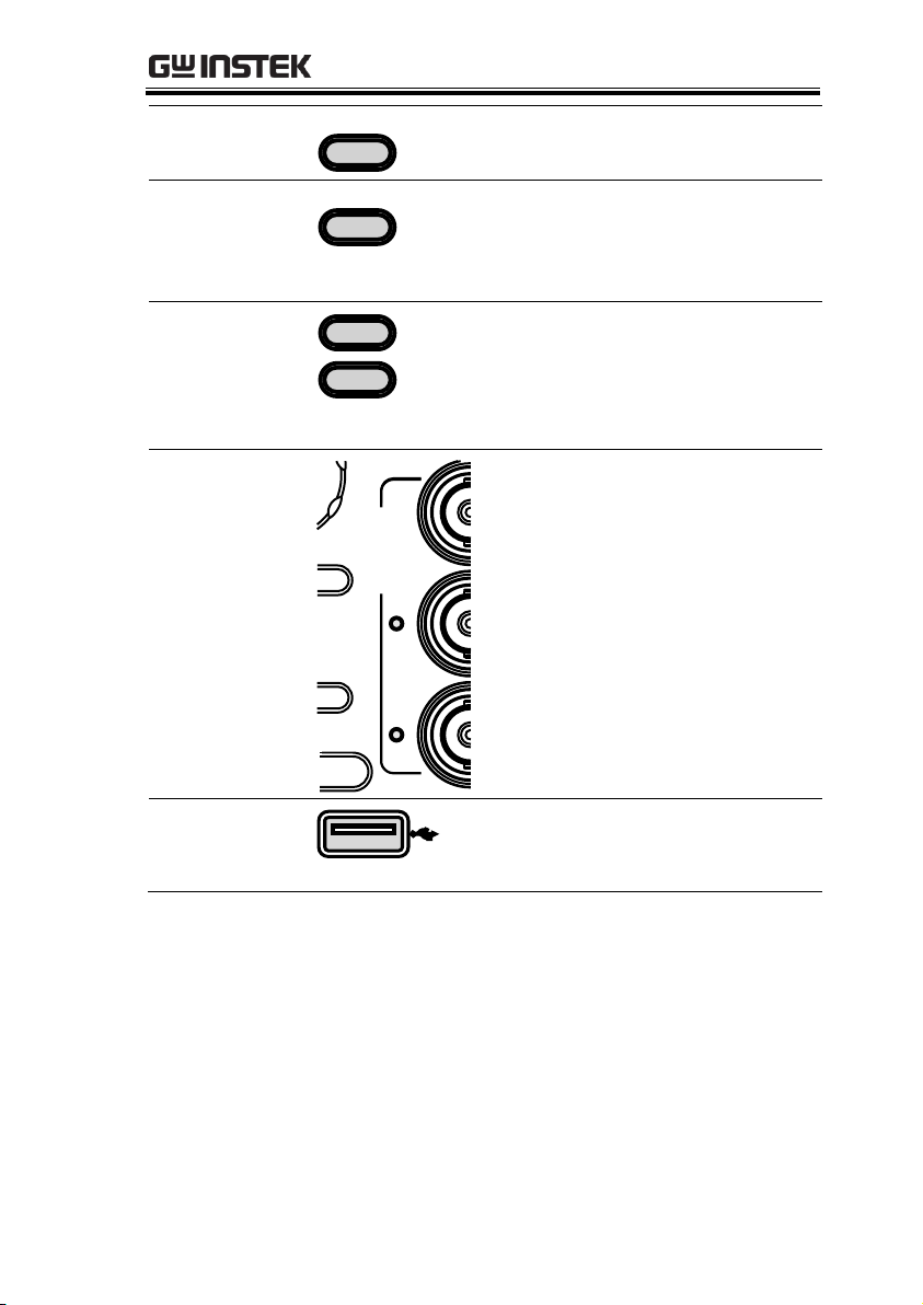
Main Output
(AFG-3021/3031)
Output
MAIN
The Output key is used to turn on
or off the waveform output.
CH1/CH2
Output
(AFG-3022/3032)
Output
CH1
CH1/CH2 Output key. These
keys are used to turn the output
on or off for each individual
channel.
CH1/CH2
(AFG-3022/3032)
CH1
CH2
The CH1/CH2 keys are used to
access the DSO link function,
output impedance settings and
phase settings for the AFG-3022 &
AFG-3032.
Output
indicators
OUTPUT
When an Output indicator is
green, it indicates that the output
is active.
USB host
connector
The USB Host connector is used
to save and restore data as well as
update the firmware.
17
Page 18
AFG-3021/3022/3031/3032 User Manual
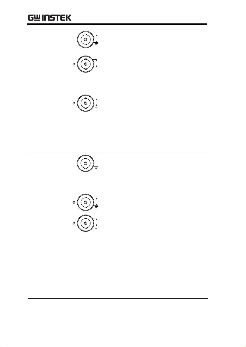
Output terminals
(AFG-3021/3031)
MOD
42V
MAX
Modulation output terminal for
the AM, FM, PWM, PM, SUM or
sweep function.
50
W
SYNC
42V
MAX
The SYNC output terminal
outputs a TTL logic level signal in
phase with the zero phase
position of the main output. 50Ω
output impedance.
50
W
MAIN
42V
MAX
The primary output terminal. 50Ω
output impedance.
Note: The MAIN ground has a common ground
with the MOD output, SYNC and MOD input
terminals. They are also isolated from the chassis
ground and the 10MHz REF IN ground by an
isolation voltage of 42Vpk.
Output terminals
(AFG-3022/3032)
SYNC
42V
MAX
50
W
The SYNC output terminal
outputs a TTL logic level signal in
phase with the zero phase
position of the CH1 output. 50Ω
output impedance.
50
W
CH2
42V
MAX
CH2 output terminal. 50Ω output
impedance.
50
W
CH1
42V
MAX
CH1 output terminal. 50Ω output
impedance.
Note: The CH1, CH2 and 10MHz REF IN ground
are isolated from each other and from the chassis
ground by an isolation voltage of 42Vpk.
The CH1 ground has a common ground with the
MOD output, SYNC and the CH1 MOD input
terminals.
The CH2 ground has a common ground with the
CH2 MOD input terminal.
18
Page 19
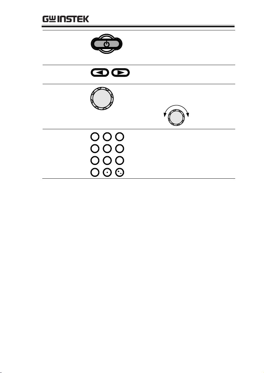
GETTING STARTED
Standby key
The standby key is used to turn
the function generator on (green)
or to put the function generator
into standby mode (red).
Selection keys
Used to select digits when editing
parameters.
Scroll Wheel
The scroll wheel is used to edit
values and parameters.
Decrease Increase
Keypad
0
/
321
4
7 859
6
The digital keypad is used to
enter values and parameters. The
keypad is often used in
conjunction with the selection
keys and variable knob.
19
Page 20
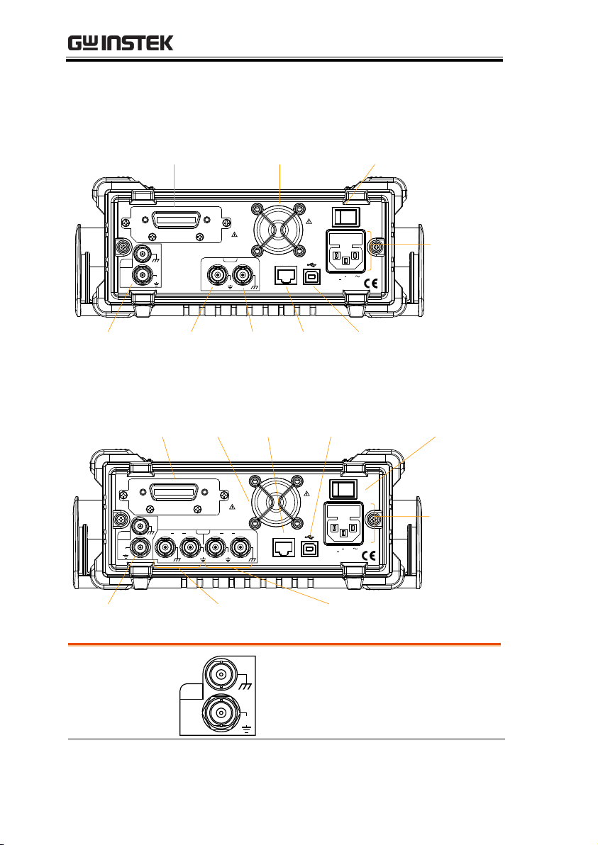
Rear Panel
WARNING
LAN
replacing fuse
Disconnect power
cord and test
leads before
100 240V
50 60Hz 50VA
AC
AC 250V
T 0.63A
FUSE RATING
GPIB
must be connected to ground.
For continued fire protection. Replace only with specified type and rated fuse.
No operator serviceable components inside.
Do not remove covers. Refer servicing to qualified personnel.
To avoid electric shock the power cord protective grounding conductor
OUT
INPUT
42V
MAX
IN
TriggerMOD
42V
MAX
REF
10MHz
GPIB Fan
OUT and IN
10MHz REF
USB portTrigger
Input
Power
socket and
fuse
Power Switch
MOD
Input
LAN
REF
OUT
INPUT
42V
MAX
10MHz
42V
MAX
IN
WARNING
LAN
replacing fuse
Disconnect power
cord and test
leads before
100 240V
50 60Hz 85VA
AC
AC 250V
T 1A
FUSE RATING
GPIB
must be connected to ground.
For continued fire protection. Replace only with specified type and rated fuse.
No operator serviceable components inside.
Do not remove covers. Refer servicing to qualified personnel.
To avoid electric shock the power cord protective grounding conductor
42V
MAX
CH2
Trigger MOD
CH1
TriggerMOD
GPIB Fan
OUT and IN
10MHz REF
CH1 MOD &
Trigger Input
Power
socket and
fuse
USB port Power Switch
CH2 MOD &
Trigger Input
LAN
10MHz REF OUT
OUT
IN
42V
MAX
REF
10 MHz reference output.
10MHz REF IN
10 MHz reference input.
AFG-3021/3031
AFG-3022/3032
AFG-3021/3022/3031/3032 User Manual
20
Page 21
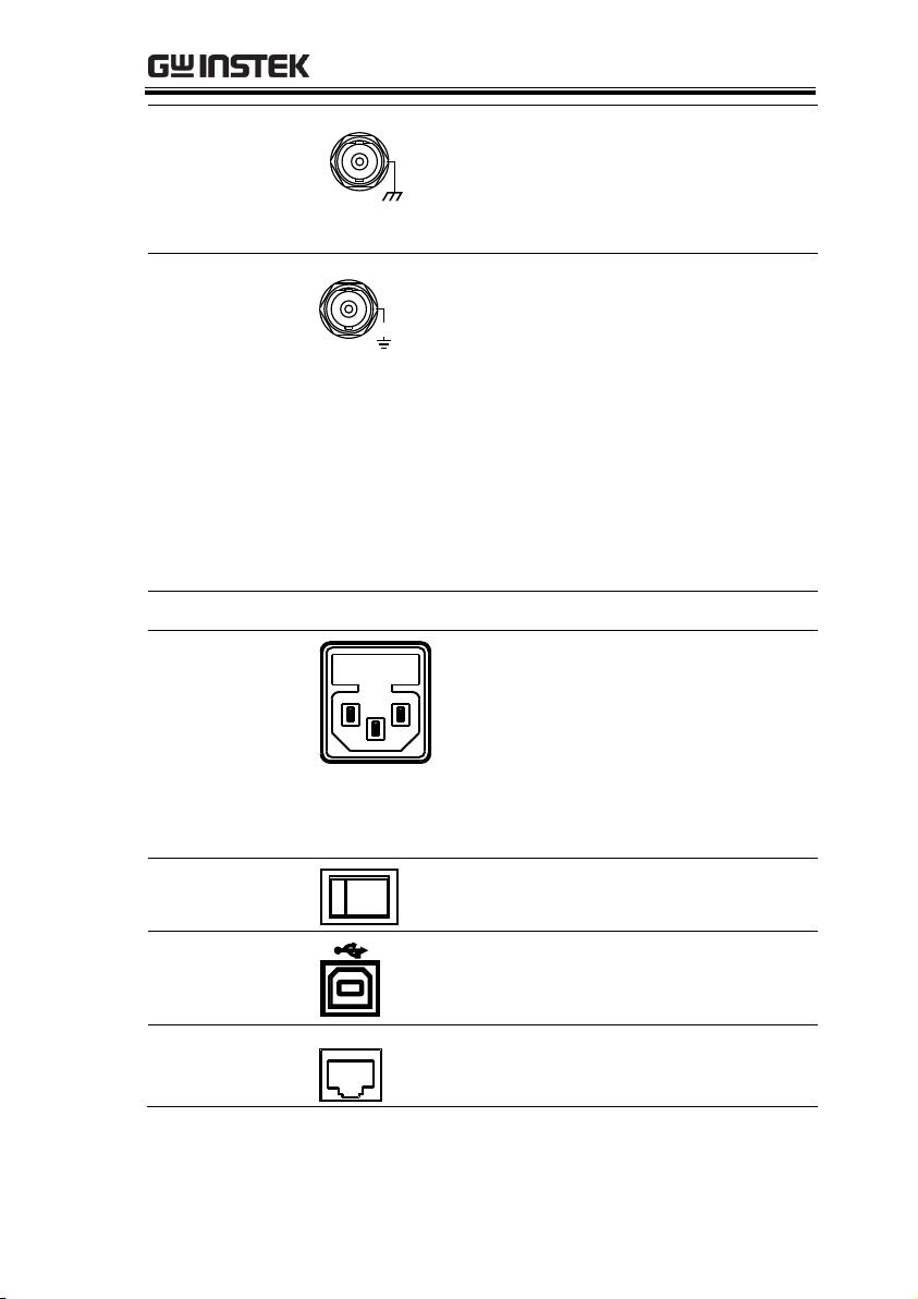
GETTING STARTED
Trigger Input
Trigger
External trigger input. Used to
receive external trigger signals. For
the AFG-3022/3032 there is a
separate trigger input for CH1 and
CH2.
MOD input
42V
MAX
MOD
Modulation input terminal. For the
AFG-3022/3032 there is a separate
modulation input for CH1 and
CH2.
Note: The CH1/CH2 MOD input terminals are
isolated from each other and from the chassis
ground by an isolation voltage of 42Vpk.
The CH1 MOD input shares ground with the CH1
ground.
The CH2 MOD input shares ground with the CH2
ground.
Fan
Power Socket
Input and fuse
Power input: 100-240V AC
50-60Hz.
Fuse:
AFG-3022/3032: T1A/250V
AFG-3021/AFG-3031: T0.63A/250V
For the fuse replacement procedure,
see page 405.
Power Switch
Main power switch.
USB B port
The USB B connector is used to
connect the function generator to a
PC for remote control.
LAN port
LAN
Ethernet port used for remote
control (RJ45 connector).
21
Page 22

AFG-3021/3022/3031/3032 User Manual
GPIB
GPIB
24 pin female GPIB
connector for PC remote
control.
22
Page 23
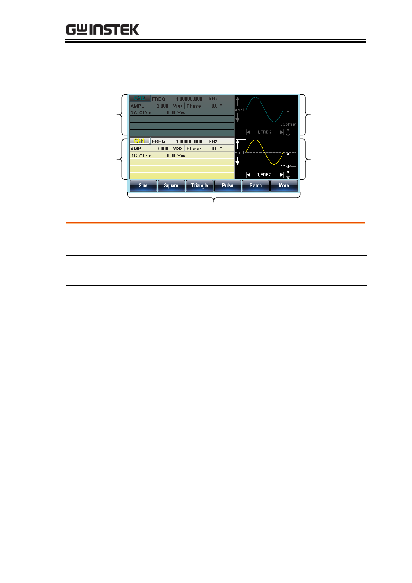
Display
CH1
Waveform
Display
Soft Menu Keys
CH2
Waveform
Display
CH1
Parameter
Window
CH2
Parameter
Window
Parameter
Windows
These windows are used to edit the parameter
values for CH1 and CH2.
Waveform Display
The Waveform Display is used give an indication
of the expected waveform output for each channel.
Soft Menu Keys
The function keys (F1~F6) below the Soft Menu
keys correspond to the soft keys.
GETTING STARTED
23
Page 24
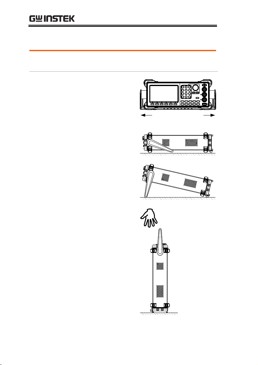
AFG-3021/3022/3031/3032 User Manual
Background
This section describes how to adjust the handle
and power up the function generator.
Adjusting the
stand
Pull out the handle
sideways and rotate
it.
Place the unit
horizontally,
or tilt the stand.
Place the handle
vertically to hand
carry.
Setting up the Function Generator
24
Page 25
GETTING STARTED
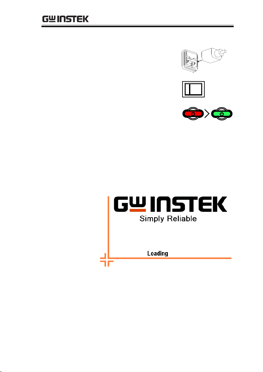
Power Up
1. Connect the power cord to
the socket on the rear panel.
2. Turn on the power switch
on the rear panel.
3. Press and hold the Standby
key on the front panel to
turn the machine on. The
standby key will change
from red (standby) to green
(on).
Standby
On
4. When the standby key turns green, the
instrument will turn on showing a loading
screen.
The function generator is now ready to be used.
25
Page 26

AFG-3021/3022/3031/3032 User Manual
How to use the Digital Inputs ............................................ 28
How to use the Help Menu ................................................ 29
Selecting a Waveform ........................................................ 32
Square Wave ........................................................................ 32
Triangle Wave ....................................................................... 32
Sine Wave ............................................................................. 33
Pulse Wave ........................................................................... 33
Noise Wave .......................................................................... 34
Harmonic Wave ................................................................... 34
Modulation ........................................................................ 36
AM ........................................................................................ 36
FM ........................................................................................ 37
FSK Modulation ................................................................... 38
PM ........................................................................................ 39
SUM Modulation ................................................................. 40
PWM Modulation ................................................................. 41
Sweep ................................................................................ 42
Burst ................................................................................. 43
ARB ................................................................................... 44
ARB – Add Built-In Waveform ............................................. 44
ARB – Add Built-In Waveform - Pulse ................................. 44
ARB - Add Point ................................................................... 45
ARB - Add Line ..................................................................... 45
ARB – Output Section .......................................................... 46
ARB – Output N Cycle ......................................................... 46
ARB – Output Infinite Cycles ............................................... 47
QUICK REFERENCE
This chapter lists operation shortcuts, built-in help coverage, and
default factory settings. Use this chapter as a quick reference for
instrument functions. For detailed explanations on parameters,
settings and limitations, please see the Operation chapter(page 70),
Modulation chapter(page 89), Secondary System Function Settings
chapter (page 158), Dual Channel & Multi-Unit Operation
chapter(page 177) or the Specifications (page 406).
26
Page 27

QUICK REFERENCE
Utility Menu ...................................................................... 48
Save ...................................................................................... 48
Recall .................................................................................... 48
Interface GPIB ...................................................................... 48
Interface LAN ....................................................................... 49
Interface USB ....................................................................... 49
Dual Channel – Frequency Coupling ................................... 49
Dual Channel – Amplitude Coupling ................................... 49
Dual Channel – Tracking ...................................................... 50
Menu Tree ......................................................................... 51
Waveform ............................................................................. 51
Waveform - Pulse ................................................................. 52
Waveform - More ................................................................. 52
ARB-Display .......................................................................... 53
ARB-Edit ............................................................................... 54
ARB-Built-in .......................................................................... 55
ARB-Built in-Basic ................................................................ 56
ARB-Save .............................................................................. 57
ARB-Load .............................................................................. 57
ARB-Output .......................................................................... 58
MOD ..................................................................................... 59
Sweep - Type/MOD = Frequency ......................................... 60
Sweep - More ........................................................................ 60
Sweep - Type/MOD = Amplitude......................................... 61
Burst – N Cycle ..................................................................... 62
Burst - Gate .......................................................................... 62
CH1 / CH2 (AFG-3022/AFG-3032 Only) ............................. 63
UTIL (AFG-3021/3031) ........................................................ 63
UTIL (AFG-3022/AFG-3032) ................................................ 64
UTIL - Interface ..................................................................... 64
UTIL - Interface - LAN .......................................................... 65
UTIL - Interface - LAN - Config - Manual ............................. 66
UTIL - System ....................................................................... 66
UTIL - Dual Channel ............................................................. 67
Default Settings ................................................................ 68
27
Page 28
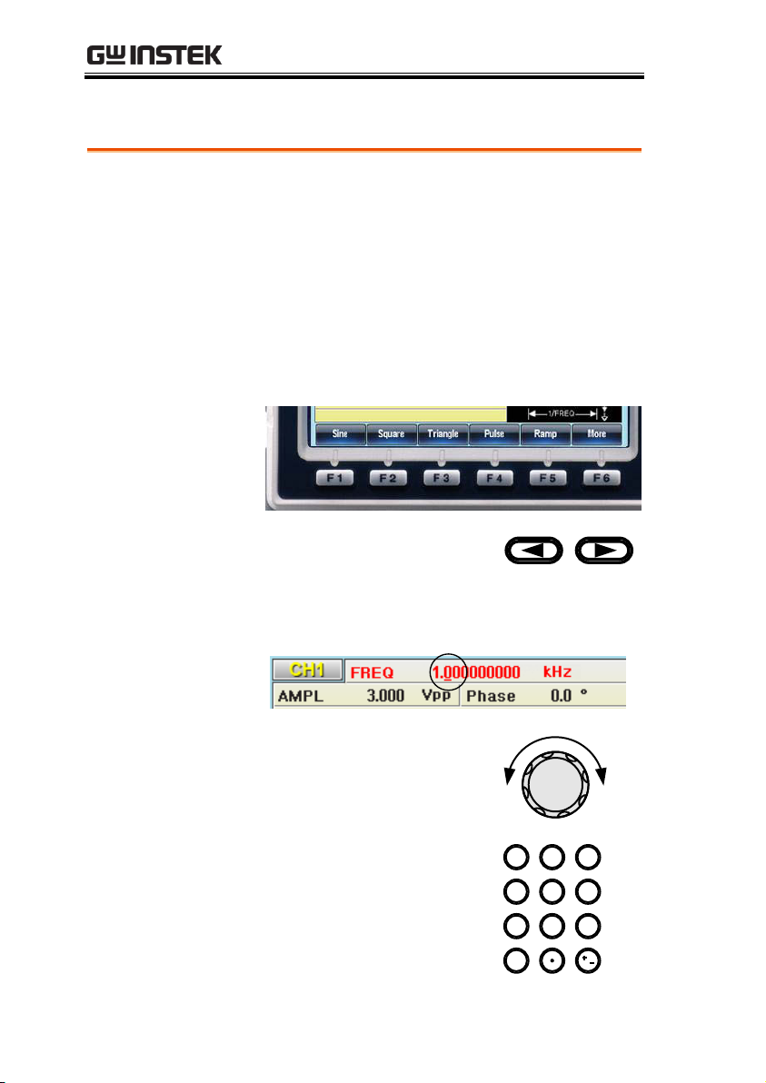
QUICK REFERENCE
Background
The AFG-30XX has three main types of digital
inputs: the number pad, selection keys and scroll
wheel. The following instructions will show you
how to use the digital inputs to edit parameters.
1. To select a menu item, press the corresponding
function keys below (F1~F6). In the example
below, the F1 function key corresponds to the
Soft key “Sine”.
2. To edit a digital value, use
the selector key to move the
cursor to the digit that needs
to be edited.
3. Use the scroll wheel to edit
the digit under the cursor.
Clockwise increases the
value, counterclockwise
decreases the value.
0
/
321
4
7 859
6
4. Alternatively, the number
pad can be used to set the
value of a highlighted
parameter.
How to use the Digital Inputs
28
Page 29
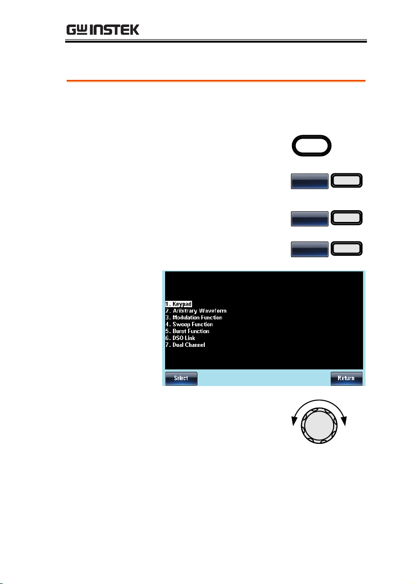
How to use the Help Menu
Background
Every key and function has a detailed description
in the help menu.
1. Press UTIL.
UTIL
2. Press System (F4)[F5 for the
AFG-3021/3031].
System
F 4
3. Press More (F5).
More
F 5
4. Press Help (F2).
Help
F 2
5. Use the scroll wheel to
navigate to a help item. Press
Select to choose the item.
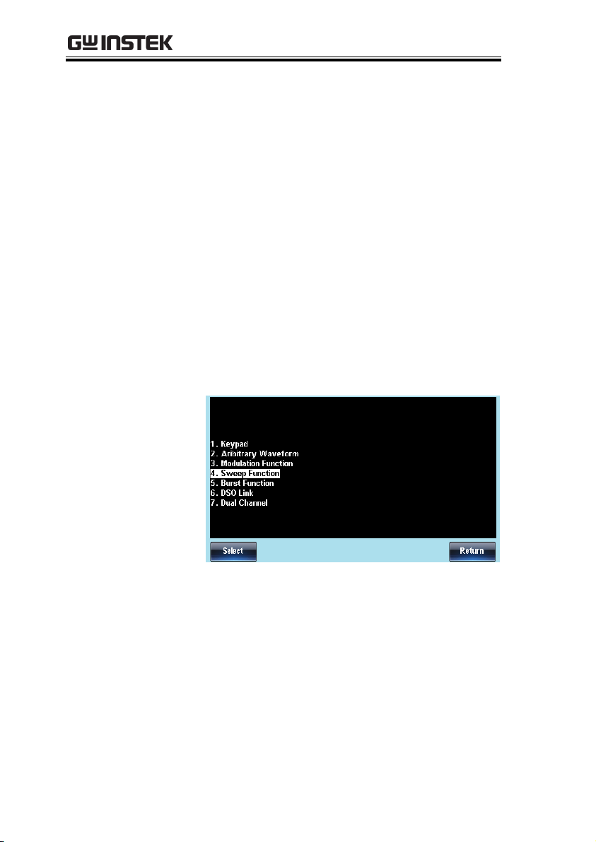
Keypad
Provides help on any front panel
key that is pressed.
Arbitrary
Waveform
Explains how to create arbitrary
waveforms.
QUICK REFERENCE
29
Page 30
AFG-3021/3022/3031/3032 User Manual
Modulation
Function
Explains how to create
Modulated waveforms.
Sweep Function
Provides help on the Sweep
function.
Burst Function
Provides help on the Burst
function.
DSO Link
Provides help on DSO link.
Hardcopy
Explains how to use the
Hardcopy function.
Dual Channel
Describes how to perform
frequency or amplitude tracking
for the AFG-3022/3032.
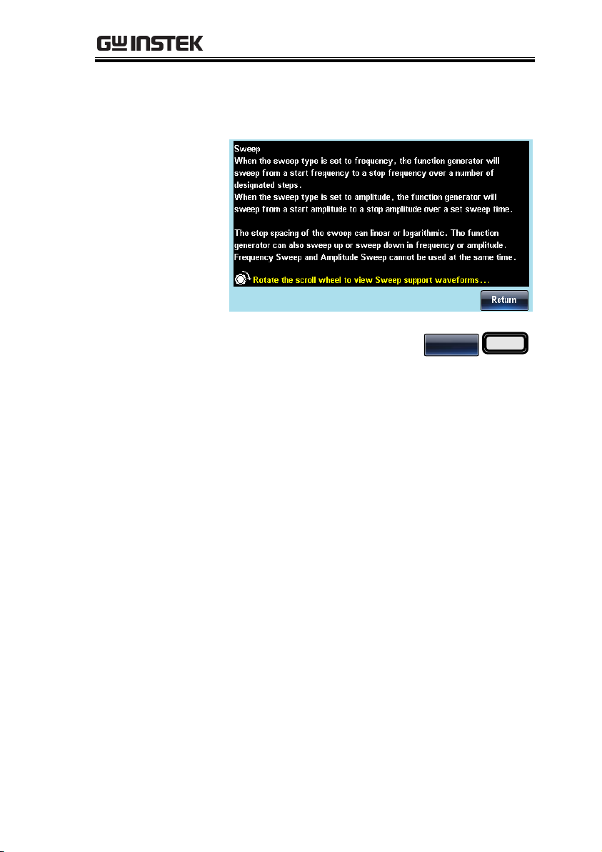
6. For example select item 5 to see help on the
sweep function.
30
Page 31
QUICK REFERENCE
7. Use the scroll wheel to navigate to each help
page.
8. Press F6 to return to the
previous menus.
Return
F 6
31
Page 32
AFG-3021/3022/3031/3032 User Manual
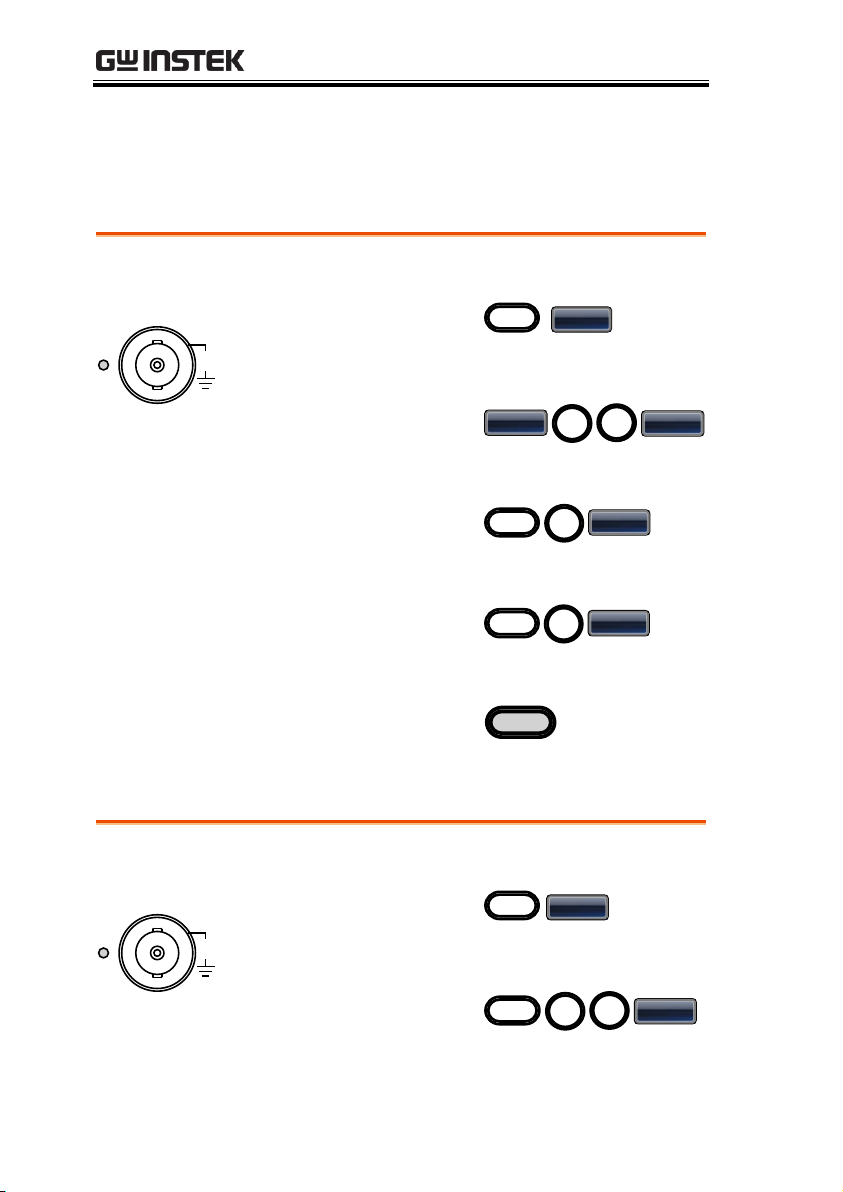
Example: Square wave, 3Vpp, 75%duty, 1 kHz
Output
50
W
CH1
42V
MAX
1. Press the Waveform
key and select Square
(F2).
Waveform
Square
2. Press Duty(F1),
followed by 7 + 5 +
%(F5)
Duty
7
5
%
Input: N/A
3. Press the FREQ/Rate
key, followed by 1 +
kHz (F5).
1
kHz
FREQ/Rate
4. Press the AMPL key,
followed by 3 + VPP
(F6).
3
VPP
AMPL
5. Press the output key.
Output
Example: Triangle wave, 5Vpp, 10kHz
Output
50
W
CH1
42V
MAX
Input: N/A
1. Press the Waveform
key and select
Triangle (F3).
Waveform
Triangle
2. Press the FREQ/Rate
key, followed by 1 + 0
+ kHz (F5).
1
0
kHz
FREQ/Rate
Selecting a Waveform
Square Wave
Triangle Wave
32
Page 33
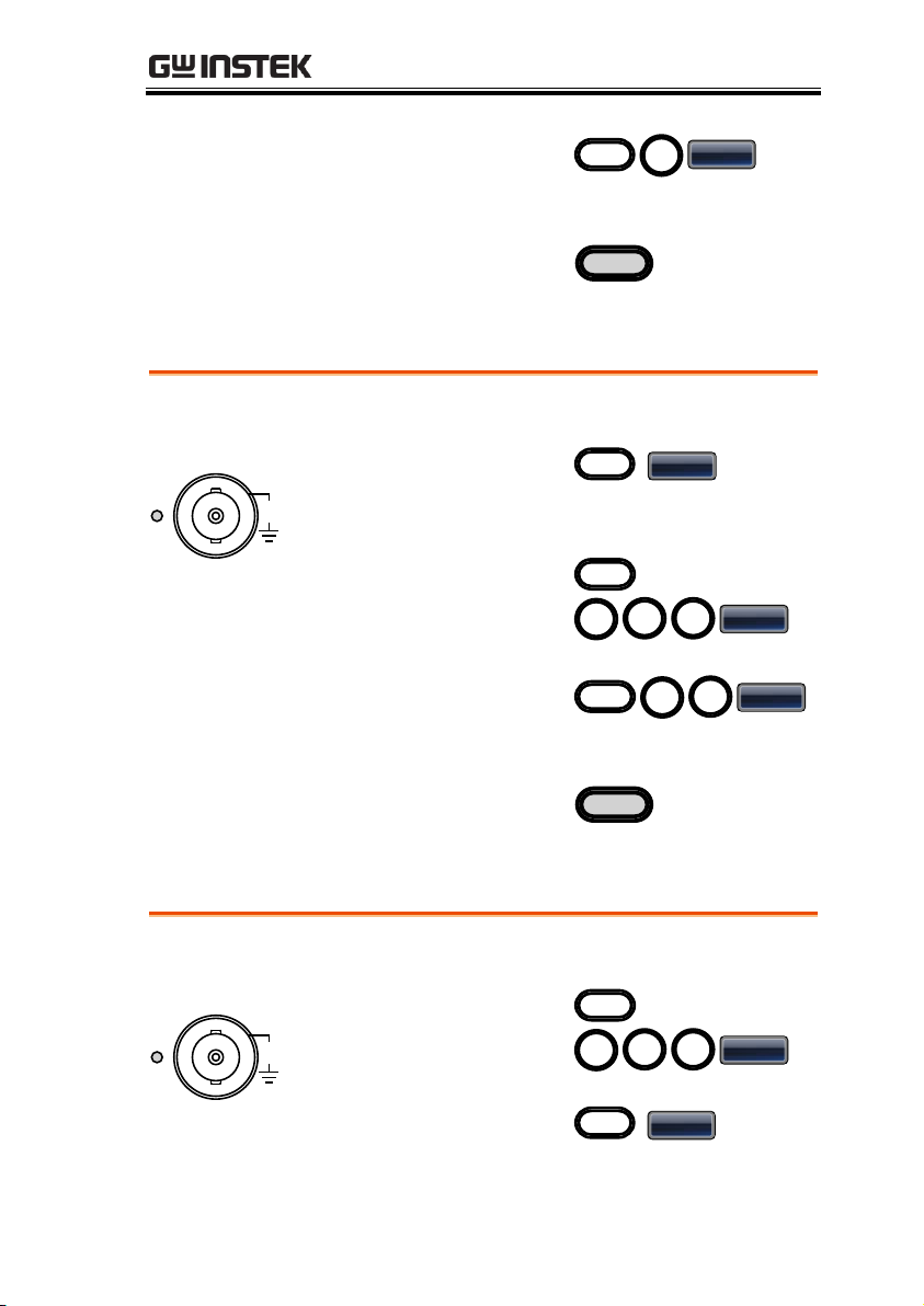
3. Press the AMPL key,
followed by 5 +VPP
(F6).
5
Vpp
AMPL
4. Press the output key.
Output
Sine Wave
Example: Sine wave, 10Vpp, 100kHz
Output
50
W
CH1
42V
MAX
Input: N/A
1. Press the Waveform
key and select Sine
(F1).
Waveform
Sine
2. Press the FREQ/Rate
key, followed by 1 + 0
+0 + kHz (F5).
FREQ/Rate
1
0 0
kHz
3. Press the AMPL key,
followed by 1 + 0
+VPP (F6).
1
0
VPP
AMPL
4. Press the output key.
Output
Example: Pulse wave, 10Vpp, 100kHz, 5us pulse width
Output
50
W
CH1
42V
MAX
Input: N/A
1. Press the FREQ/Rate
key, followed by 1 + 0
+0 + kHz (F5).
FREQ/Rate
1
0 0
kHz
2. Press the Waveform
key and select Pulse
(F4).
Waveform
Pulse
QUICK REFERENCE
Pulse Wave
33
Page 34
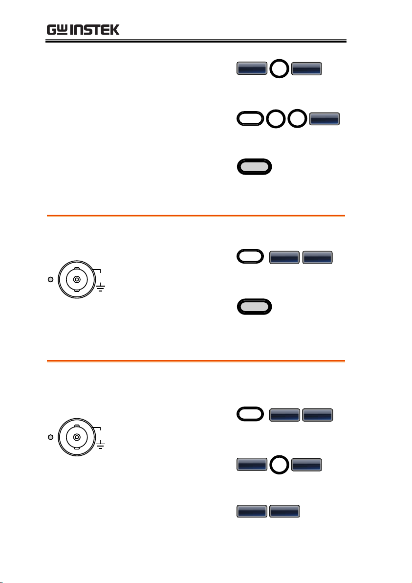
3. Press Width (F1),
followed by 5 + uSEC
(F3).
Width
5
uSEC
4. Press the AMPL key,
followed by 1 + 0
+VPP (F6).
1
0
VPP
AMPL
5. Press the output key.
Output
Noise Wave
Example: White noise output
Output
50
W
CH1
42V
MAX
Input: N/A
1. Press the Waveform
key and select More
(F6), Noise (F1).
Waveform
More
Noise
2. Press the output key.
Output
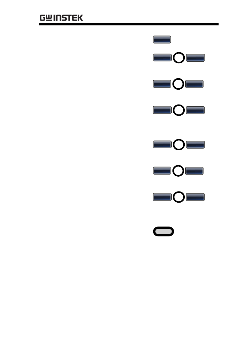
Example: 10kHz harmonic sine wave, odd & even (all) harmonics,
up to the 3rd order (2nd(5Vpp), 3rd(2Vpp), 0º phase.
Output
50
W
CH1
42V
MAX
Input: N/A
1. Press the Waveform
key and select More
(F6), Harmonic (F2).
Waveform
More Harmonic
2. Press Total (F1),
followed by 3 + Enter
(F1).
Total
3
Enter
3. Press Type (F2), ALL
(F3).
Type ALL
AFG-3021/3022/3031/3032 User Manual
Harmonic Wave
34
Page 35
QUICK REFERENCE
4. Press Order (F3).
Order
5. Press Order (F1),
followed by 2 + Enter
(F1).
Press Amp(F2),
followed by 5 +
VPP (F2).
Press Phase(F3),
followed by 0 +
Degree (F1).
Order
2
Enter
Ampl
5
VPP
Phase
0
Degree
6. Press the Order (F1),
followed by 3 + Enter
(F1).
Press Amp(F2),
followed by 2 +
VPP (F2).
Press Phase(F3),
followed by 0 +
Degree (F1).
Order
3
Enter
Ampl
2
VPP
Phase
0
Degree
7. Press the output key.
Output
35
Page 36
Modulation
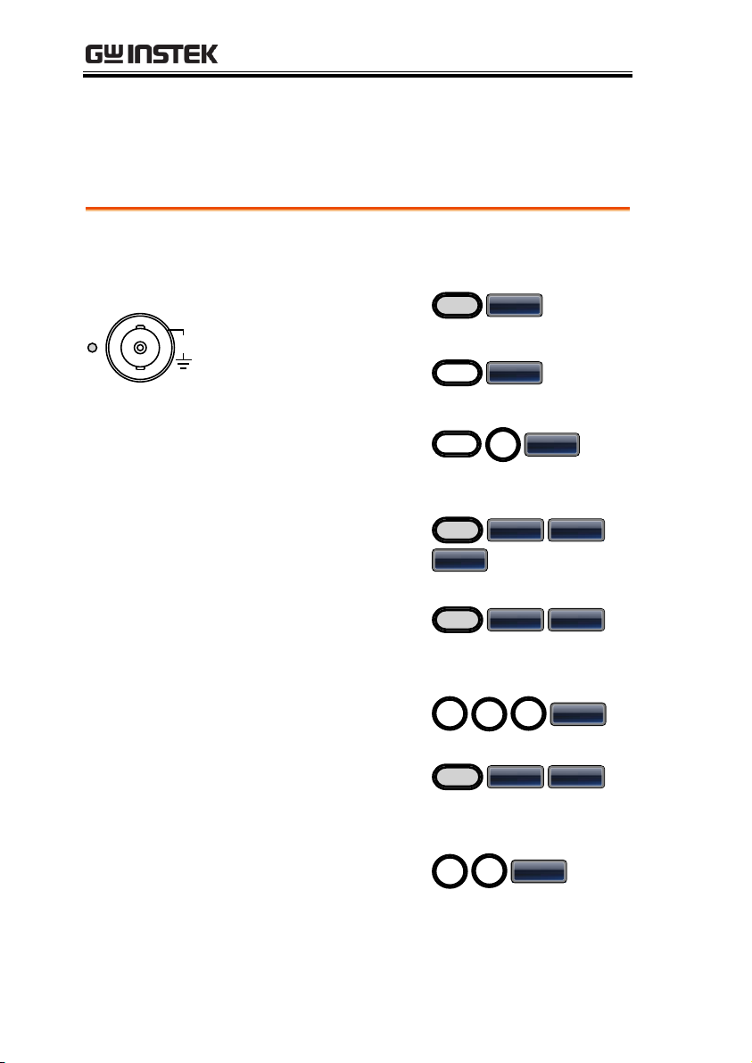
Example: AM modulation. 100Hz modulating square wave. 1kHz
Sine wave carrier. 80% modulation depth.
Output
50
W
CH1
42V
MAX
1. Press the MOD key
and select AM (F1).
MOD
AM
2. Press Waveform and
select Sine (F1).
Waveform
Sine
Input: N/A
3. Press the Freq/Rate
key, followed by 1 +
kHz (F5).
1
kHz
FREQ/Rate
4. Press the MOD key,
select AM (F1), Shape
(F4), Square (F2).
MOD
AM Shape
Square
5. Press the MOD key,
select AM (F1), AM
Freq (F3).
MOD
AM AM Freq
6. Press 1 + 0 + 0 + Hz
(F2).
0
0
Hz
1
7. Press the MOD key,
select AM (F1), Depth
(F2).
MOD
AM Depth
8. Press 8 + 0 + % (F1).
8
0
%
AM
AFG-3021/3022/3031/3032 User Manual
36
Page 37
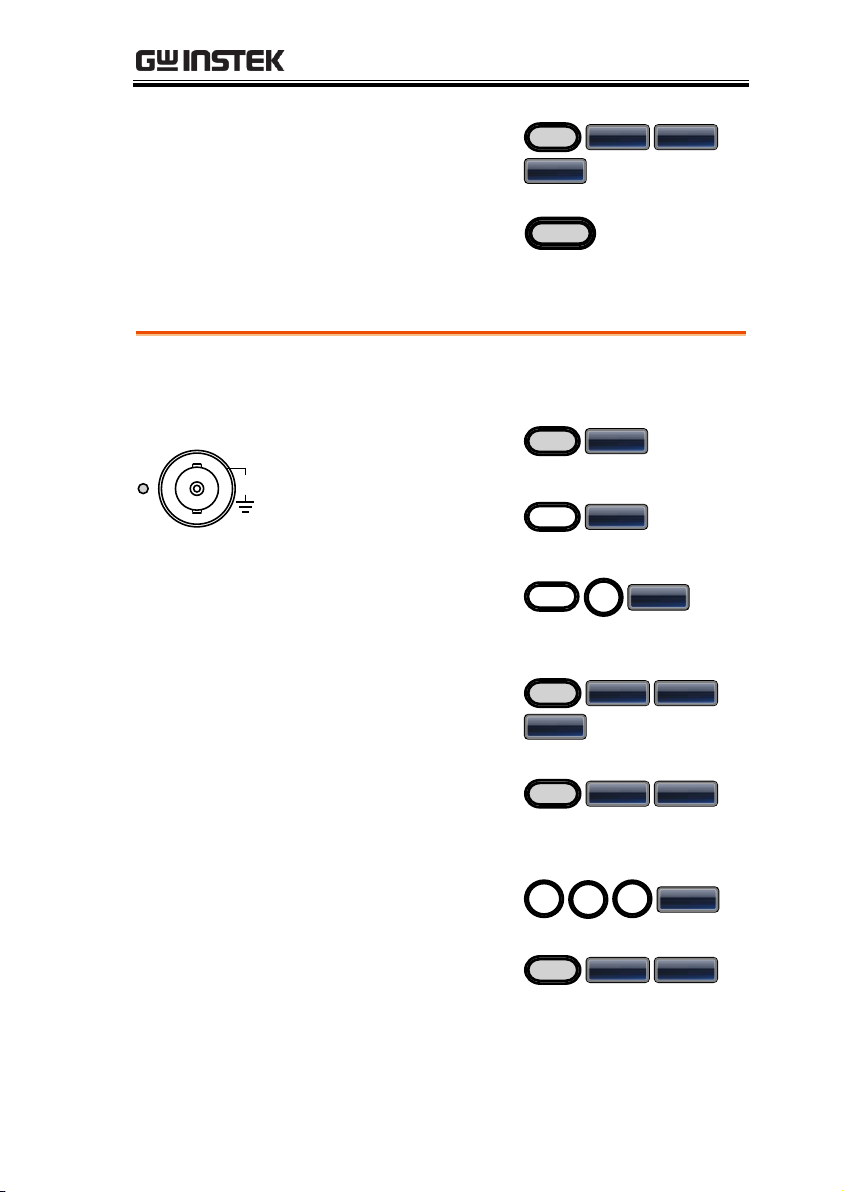
9. Press MOD, AM (F1),
Source (F1), INT (F1).
MOD
AM Source
INT
10. Press the output key.
Output
FM
Example: FM modulation. 100Hz modulating square wave. 1kHz
sine wave carrier. 100 Hz frequency deviation. Internal source.
Output
50
W
CH1
42V
MAX
1. Press the MOD key
and select FM (F2).
MOD
FM
2. Press Waveform and
select Sine (F1).
Waveform
Sine
Input: N/A
3. Press the Freq/Rate
key, followed by 1 +
kHz (F5).
1
kHz
FREQ/Rate
4. Press the MOD key,
select FM (F2), Shape
(F4), Square (F2).
MOD
FM Shape
Square
5. Press the MOD key,
select FM (F2), FM
Freq (F3).
MOD
FM FM Freq
6. Press 1 + 0 + 0 + Hz
(F2).
0
0
Hz
1
7. Press the MOD key,
select FM (F2), Freq
Dev (F2).
MOD
FM Freq Dev
QUICK REFERENCE
37
Page 38
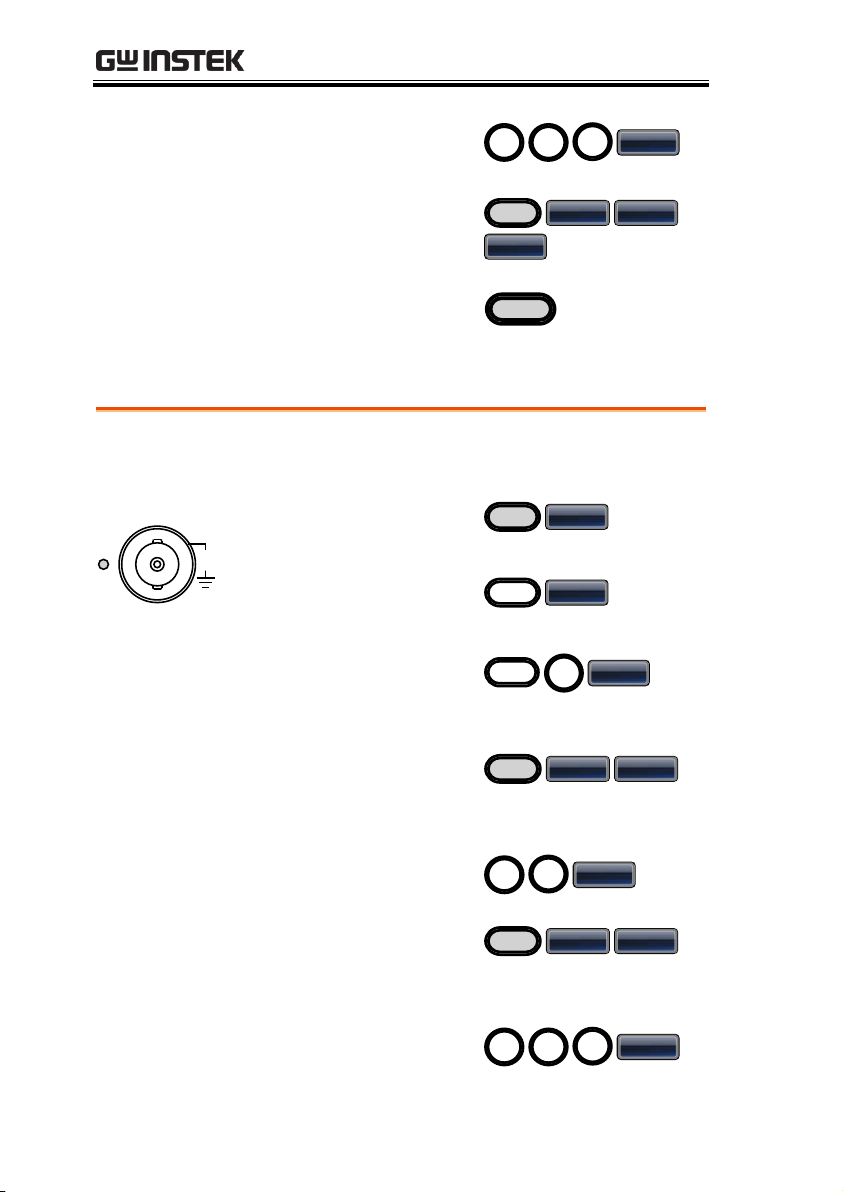
8. Press 1 + 0 + 0 + Hz
(F3).
0
0
Hz
1
9. Press MOD, FM (F2),
Source (F1), INT (F1).
MOD
FM
Source
INT
10. Press the output key.
Output
FSK Modulation
Example: FSK modulation. 100Hz hop frequency. 1kHz carrier
wave. Triangle wave. 10 Hz rate. Internal source.
Output
50
W
CH1
42V
MAX
1. Press the MOD key
and select FSK (F3).
MOD
FSK
2. Press Waveform and
select Triangle (F3).
Waveform
Triangle
Input: N/A
3. Press the Freq/Rate
key, followed by 1 +
kHz (F5).
1
kHz
FREQ/Rate
4. Press the MOD key,
select FSK (F3), FSK
Rate (F3).
MOD
FSK FSK Rate
5. Press 1 + 0 + Hz (F2).
1
0
Hz
6. Press the MOD key,
select FSK (F3), Hop
Freq (F2).
MOD
FSK Hop Freq
7. Press 1 + 0 + 0 + Hz
(F3).
0
0
Hz
1
AFG-3021/3022/3031/3032 User Manual
38
Page 39
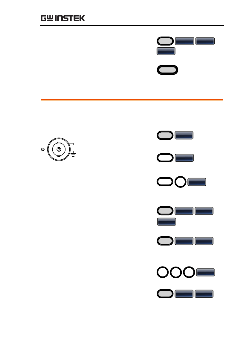
8. Press MOD, FSK (F3),
Source (F1), INT (F1).
MOD
FSK Source
INT
9. Press the output key.
Output
PM
Example: PM modulation. 100Hz phase frequency. Sine wave shape.
180° phase deviation. 1kHz sine wave carrier.
Output
50
W
CH1
42V
MAX
1. Press the MOD key
and select PM (F4).
MOD
PM
2. Press Waveform and
select Sine (F1).
Waveform
Sine
Input: N/A
3. Press the Freq/Rate
key, followed by 1 +
kHz (F5).
1
kHz
FREQ/Rate
4. Press the MOD key,
select PM (F4), Shape
(F4), Sine (F1).
MOD
PM Shape
Sine
5. Press the MOD key,
select PM (F4), PM
Freq (F3).
MOD
PM PM Freq
6. Press 1 + 0 + 0 + Hz
(F2).
0
0
Hz
1
7. Press the MOD key,
select PM (F4), Phase
Dev (F2).
MOD
PM Phase Dev
QUICK REFERENCE
39
Page 40
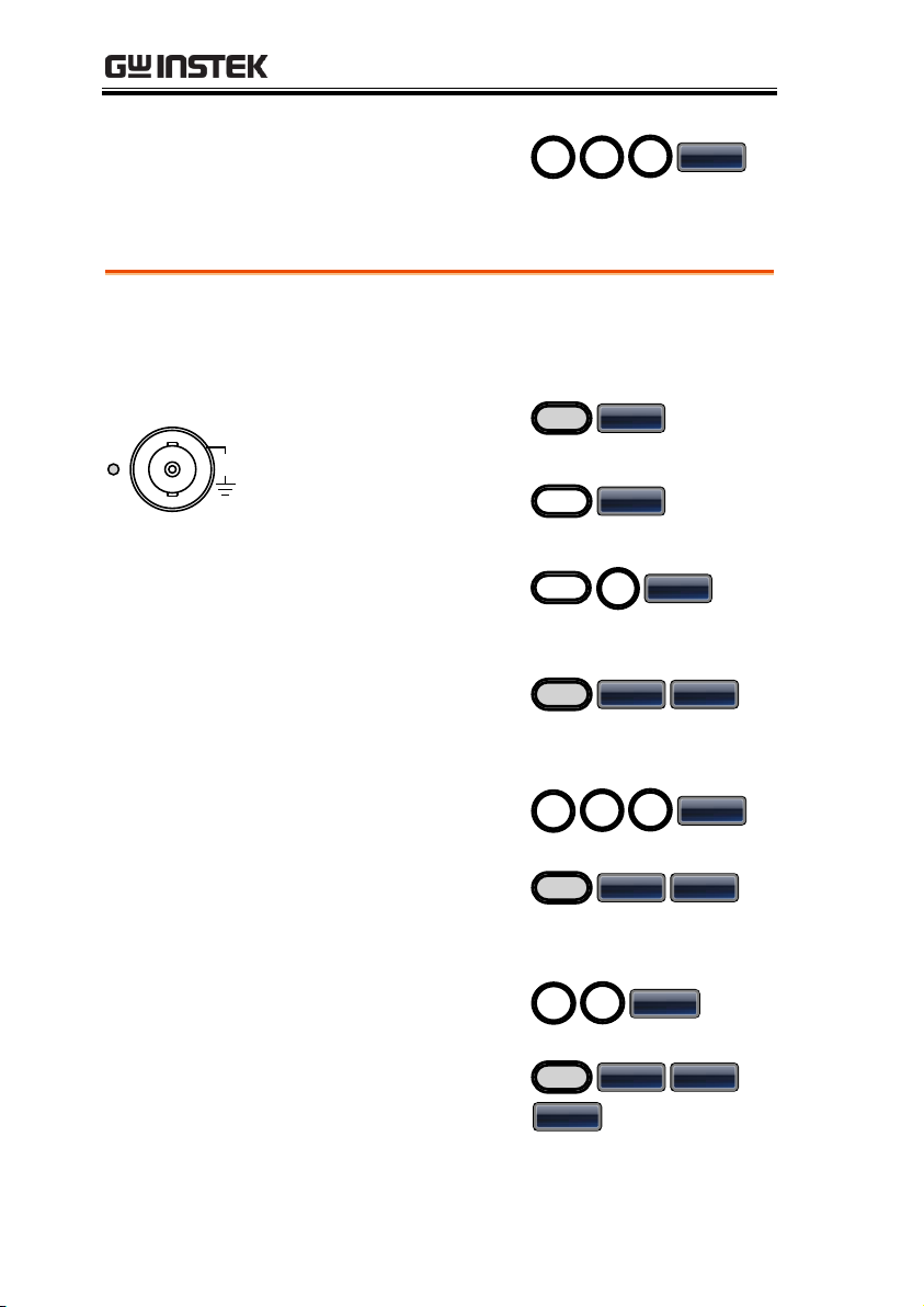
8. Press 1 + 8 + 0 +
Degree (F1).
8
0
Degree
1
SUM Modulation
Example: SUM modulation. 100Hz SUM frequency. 50% SUM
amplitude. 1kHz carrier sine wave. Triangle wave shape. Internal
source.
Output
50
W
CH1
42V
MAX
1. Press the MOD key
and select SUM (F5).
MOD
SUM
2. Press Waveform and
select Sine (F1).
Waveform
Sine
Input: N/A
3. Press the Freq/Rate
key, followed by 1 +
kHz (F5).
1
kHz
FREQ/Rate
4. Press the MOD key,
select SUM (F5), SUM
Freq (F3).
MOD
SUM SUM Freq
5. Press 1 + 0 + 0 + Hz
(F2).
0
Hz
1
0
6. Press the MOD key,
select SUM (F5), SUM
Ampl (F2).
MOD
SUM SUM Ampl
7. Press 5 + 0 + % (F1).
0
%
5
8. Press the MOD key,
select SUM (F5),
Shape (F4), Triangle
(F3).
MOD
SUM Shape
Triangle
AFG-3021/3022/3031/3032 User Manual
40
Page 41
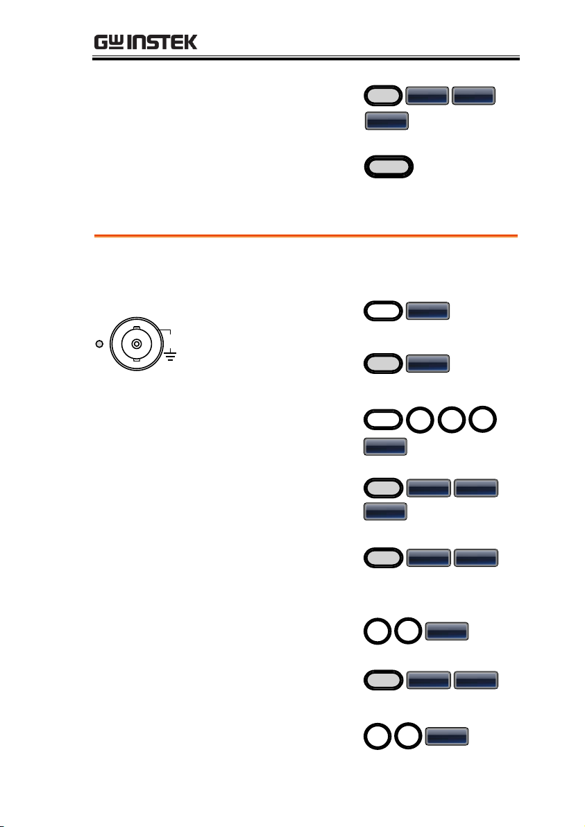
9. Press MOD, SUM
(F5), Source (F1), INT
(F1).
MOD
SUM
Source
INT
10. Press the output key.
Output
PWM Modulation
Example: PWM modulation. 800Hz carrier wave. 15 kHz
modulating sine wave. 50% duty cycle. Internal source.
Output
50
W
CH1
42V
MAX
1. Press Waveform and
select Square (F2).
Waveform
Square
2. Press the MOD key
and select PWM (F6).
MOD
PWM
Input: N/A
3. Press the FREQ/Rate
key, followed by 8 + 0
+ 0 + Hz (F4).
8
FREQ/Rate
0
0
Hz
4. Press the MOD key,
select PWM (F6),
Shape (F4), Sine (F1).
MOD
PWM Shape
Sine
5. Press the MOD key,
PWM (F6), PWM
Freq (F3).
MOD
PWM PWM Freq
6. Press 1 + 5 + kHz
(F3).
1
5
kHz
7. Press MOD, PWM
(F6), Duty (F2).
MOD
PWM Duty
8. Press 5 + 0 + % (F1).
5
0
%
QUICK REFERENCE
41
Page 42
9. Press MOD, PWM
(F6), Source (F1), INT
(F1).
MOD
PWM Source
INT
10. Press the output key.
Output
Sweep
Example: Frequency sweep. Start frequency 10mHz, stop frequency
1MHz. Log sweep, 1 second sweep, manual trigger.
Output
50
W
CH1
42V
MAX
1. Press Sweep, Start
(F3).
Sweep
Start
2. Press 1 + 0 + mHz
(F2).
0
mHz
1
3. Press Sweep, Stop
(F4).
Sweep
Stop
Input: N/A
4. Press 1 + MHz (F5).
1
MHz
5. Press Sweep,
Type/MOD (F2),
Functions (F3), Log
(F2).
Sweep
Type/MOD Functions
Log
6. Press Sweep, SWP
Time (F5).
Sweep
SWP Time
7. Press 1 + SEC (F2).
1
SEC
8. Press Sweep, TRIG
Type (F6), Manual
(F3).
Sweep
TRIG Type Manual
AFG-3021/3022/3031/3032 User Manual
42
Page 43
9. Press the output key.
Output
10. Press Trigger (F1).
Trigger
Burst
Example: Burst mode, N-Cycle (Internally triggered), 1kHz burst
frequency, burst count = 5, 10 ms burst period, 0˚ burst phase,
internal trigger, 10 us delay.
Output
50
W
CH1
42V
MAX
1. Press FREQ/Rate 1
kHz (F5).
1
kHz
FREQ/Rate
2. Press Burst, N Cycle
(F1), Cycles (F1).
Burst
N Cycle Cycles
Input: N/A
3. Press 5 + Cyc (F5).
5
Cyc
4. Press Burst, N Cycle
(F1), Period (F4).
Burst
N Cycle Period
5. Press 1 + 0 + msec
(F2).
0
mSEC
1
6. Press Burst, N Cycle
(F1), Phase (F3).
Burst
N Cycle Phase
7. Press 0 + Degree (F5).
0
Degree
8. Press Burst, N Cycle
(F1), TRIG Setup (F5),
INT (F1).
Burst
N Cycle Trig Setup
INT
QUICK REFERENCE
43
Page 44
AFG-3021/3022/3031/3032 User Manual
9. Press Burst, N Cycle
(F1), TRIG Setup (F5),
Delay (F4).
Burst
N Cycle Trig Setup
Delay
10. Press 1 + 0 + uSEC
(F2).
0
uSEC
1
11. Press the output key.
Output
Example: ARB Mode, exponential rise. Start 0, length 100, scale
32767.
Output
50
W
CH1
42V
MAX
1. Press ARB, Built in
(F3), Basic (F1), More
(F5), Exp Rise (F1).
ARB
Built in Basic
More Exp Rise
2. Press Start (F1), 0 +
Enter (F5).
0
EnterStart
3. Press Length (F2),
100, Enter (F5).
01
Length
0
Enter Return
4. Press Scale (F3),
32767, Enter (F5),
Done (F4).
23
Scale
7
6
Enter Done
7
Example: ARB Mode, Pulse. Start 0, Frequency 1kHz, Duty 25%.
ARB
ARB – Add Built-In Waveform
ARB – Add Built-In Waveform - Pulse
44
Page 45
Output
50
W
CH1
42V
MAX
1. Press ARB, Built in
(F3), Basic (F1), More
(F5), Pulse (F4).
ARB
Built in Basic
More Pulse
2. Press Frequency (F1),
1, kHz (F5).
1
kHzFrequency
3. Press Duty (F2), 25,
%(F5).
2
Duty
5
% Return
ARB - Add Point
Example: ARB Mode, Add point, Address 40, data 30,000.
Output
50
W
CH1
42V
MAX
1. Press ARB, Edit (F2),
Point (F1), Address
(F1).
ARB
Edit Point
Address
2. Press 4 + 0 + Enter
(F5).
0
Enter4Return
3. Press Data (F2),
3+0+0+0+0, Enter
(F5).
03
Data
0
0 0
Enter
Example: ARB Mode, add line, address: data (10:30, 50:100)
Output
50
W
CH1
42V
MAX
1. Press ARB, Edit (F2),
Line (F2), Start ADD
(F1).
ARB
Edit Line
Start ADD
2. Press 1 + 0 + Enter
(F5).
0
Enter1Return
QUICK REFERENCE
ARB - Add Line
45
Page 46
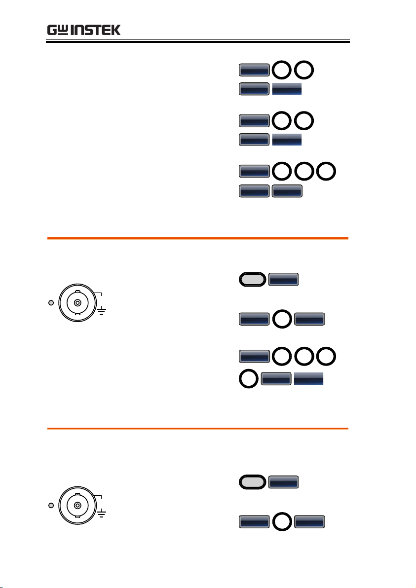
3. Press Start Data (F2),
3 + 0, Enter (F5).
03
Start Data
Enter Return
4. Press Stop ADD (F3),
5 + 0, Enter (F5).
05
Stop ADD
Enter Return
5. Press Stop Data (F4),
1 + 0 + 0, Enter (F5),
Done (F5).
01
Stop Data
0
Enter Done
ARB – Output Section
Example: ARB Mode, output ARB waveform, start 0, length 1000.
Output
50
W
CH1
42V
MAX
1. Press ARB, Output
(F6).
ARB
Output
2. Press Start (F1), 0 +
Enter (F5).
0
EnterStart
3. Press Length (F2), 1 +
0 + 0 + 0, Enter (F5).
01
Length
0
0
Enter Return
Example: ARB Mode, Output N Cycle, Start 0, Length 1000, N Cycle
10.
Output
50
W
CH1
42V
MAX
1. Press ARB, Output
(F6).
ARB
Output
2. Press Start (F1), 0 +
Enter (F5).
0
EnterStart
AFG-3021/3022/3031/3032 User Manual
ARB – Output N Cycle
46
Page 47
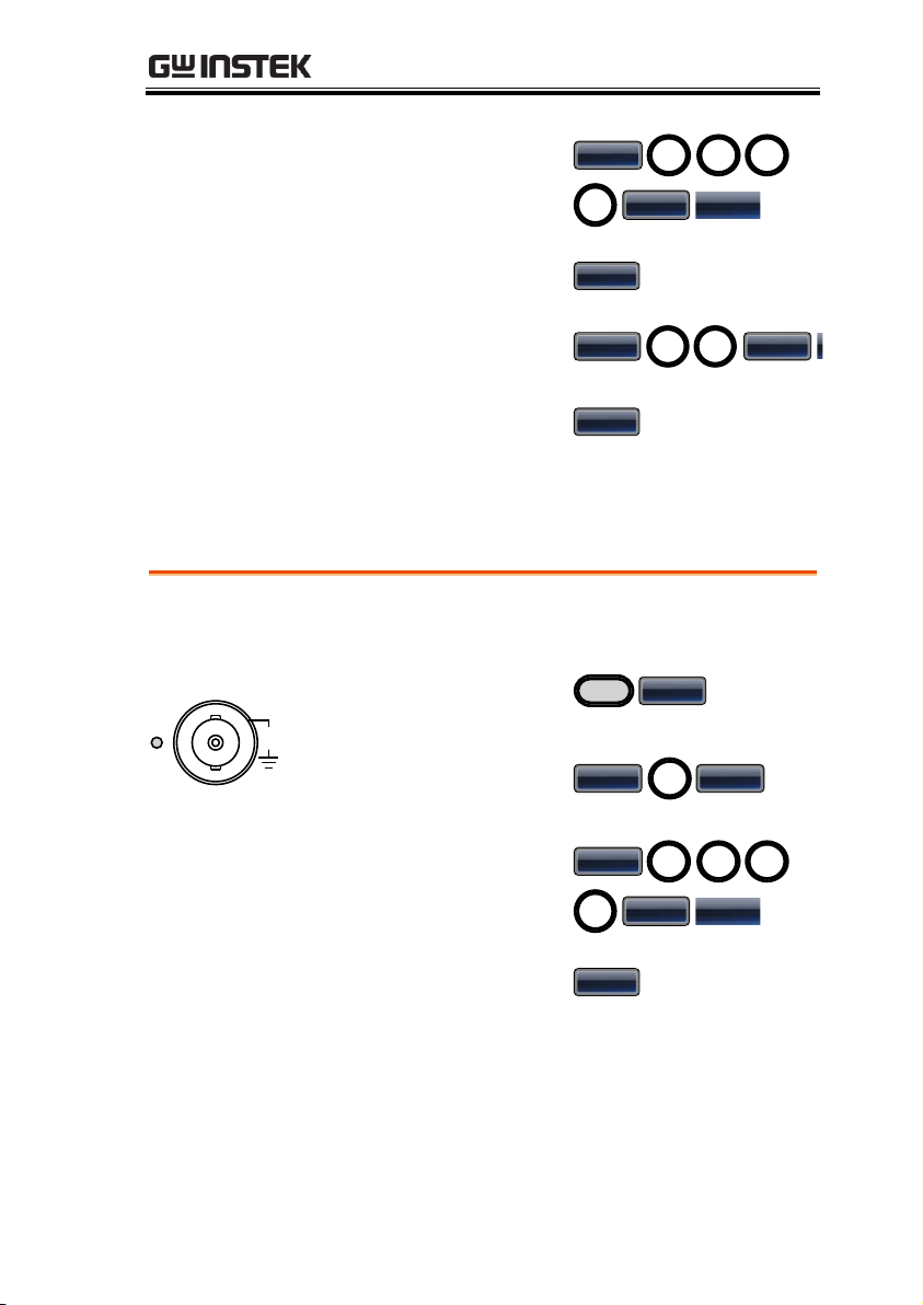
3. Press Length (F2), 1 +
0 + 0, Enter (F5).
01
Length
0
0
Enter Return
4. Press N Cycle (F4).
N Cycle
5. Press Cycles (F1), 1 +
0, Enter (F5).
1
Cycles
0
Enter Return
6. To trigger the output
once, press Trigger
(F5).
Trigger
ARB – Output Infinite Cycles
Example: ARB Mode, output N cycle, start 0, length 1000, cycles
infinite.
Output
50
W
CH1
42V
MAX
1. Press ARB, Output
(F6).
ARB
Output
2. Press Start (F1), 0 +
Enter (F5).
0
EnterStart
3. Press Length (F2), 1 +
0 + 0, Enter (F5).
01
Length
0
0
Enter Return
4. Press Infinite (F5).
Infinite
QUICK REFERENCE
47
Page 48
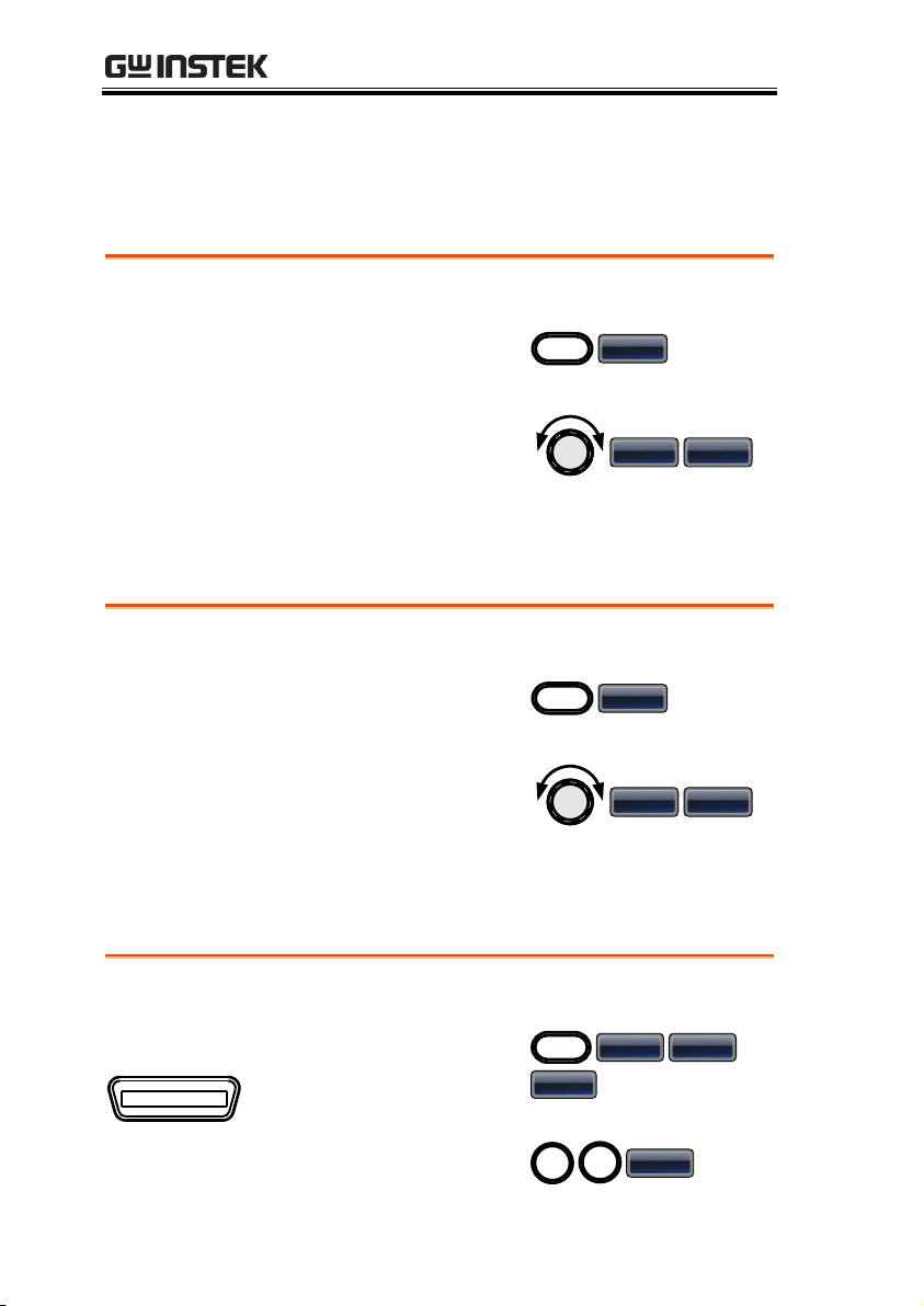
Utility Menu
Example: Save to memory file #5.
1. Press UTIL, Memory
(F1).
UTIL
Memory
2. Choose a file using
the scroll wheel and
press Store (F1), press
Done (F5).
Store Done
Example: Recall memory file #5.
1. Press UTIL, Memory
(F1).
UTIL
Memory
2. Choose a file using
the scroll wheel and
press Recall (F2),
press Done (F5).
Recall Done
Example: GPIB interface, address 10.
GPIB
GPIB
1. Press UTIL, Interface
(F2), GPIB (F1),
Address (F1).
UTIL
Interface GPIB
Address
2. Press 1 + 0 + Done
(F5).
1
0
Done
Save
Recall
AFG-3021/3022/3031/3032 User Manual
Interface GPIB
48
Page 49
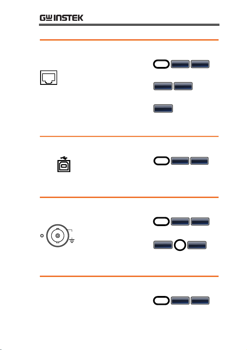
Interface LAN
Example: LAN interface, DHCP IP configuration.
LAN
LAN
1. Press UTIL, Interface
(F2), LAN (F3).
UTIL
Interface LAN
2. Press Config (F2),
DHCP (F1).
Config DHCP
3. Press Done (F3).
Done
Example: USB interface.
USB B
1. Press UTIL, Interface
(F2), USB (F2).
UTIL
Interface USB
Example: 1kHz offset coupling. AFG-3022, 3032 only.
Output
50
W
CH1
42V
MAX
1. Press UTIL, Dual Ch
(F5), Freq Cpl (F1).
UTIL
Dual Ch Freq Cpl
2. Press Offset (F2), 1 +
0 + kHz (F4).
Offset
1
kHz
Example: Amplitude coupling. AFG-3022, 3032 only.
Output
1. Press UTIL, Dual Ch
(F5), Ampl Cpl (F2).
UTIL
Dual Ch Ampl
Interface USB
QUICK REFERENCE
Dual Channel – Frequency Coupling
Dual Channel – Amplitude Coupling
49
Page 50
50
W
CH1
42V
MAX
2. Press ON (F1).
ON
Dual Channel – Tracking
Example: Inverted tracking. AFG-3022, 3032 only.
Output
50
W
CH1
42V
MAX
1. Press UTIL, Dual Ch
(F5), Tracking (F3).
UTIL
Dual Ch Tracking
2. Press Inverted (F3).
Inverted
AFG-3021/3022/3031/3032 User Manual
50
Page 51
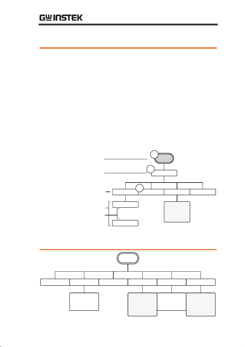
Menu Tree
Convention
Use the menu trees as a handy reference for the
function generator functions and properties. The AFG3021/3022/3031/3032 menu system is arranged in a
hierarchical tree. Each hierarchical level can be
navigated with the operation or soft menu keys.
Pressing the Return soft key will return you to the
previous menu level.
For example: To set the interface to USB;
(1)Press the UTIL key.
(2)The Interface soft-key.
(3) USB.
GPIB USB LAN Return
Clear
Done
Return
Address
Return
Interface
UTIL
1
2
3
Level 2
Level 3
Level 4
Level 5
Level 1
Go to the
UTIL –
Interface –
LAN menu
Duty
%
Return
Waveform
SYM
%
Return
Sine Square Triangle Pulse Ramp More
Go to the
Pulse menu
Go to the
More menu
QUICK REFERENCE
Waveform
51
Page 52
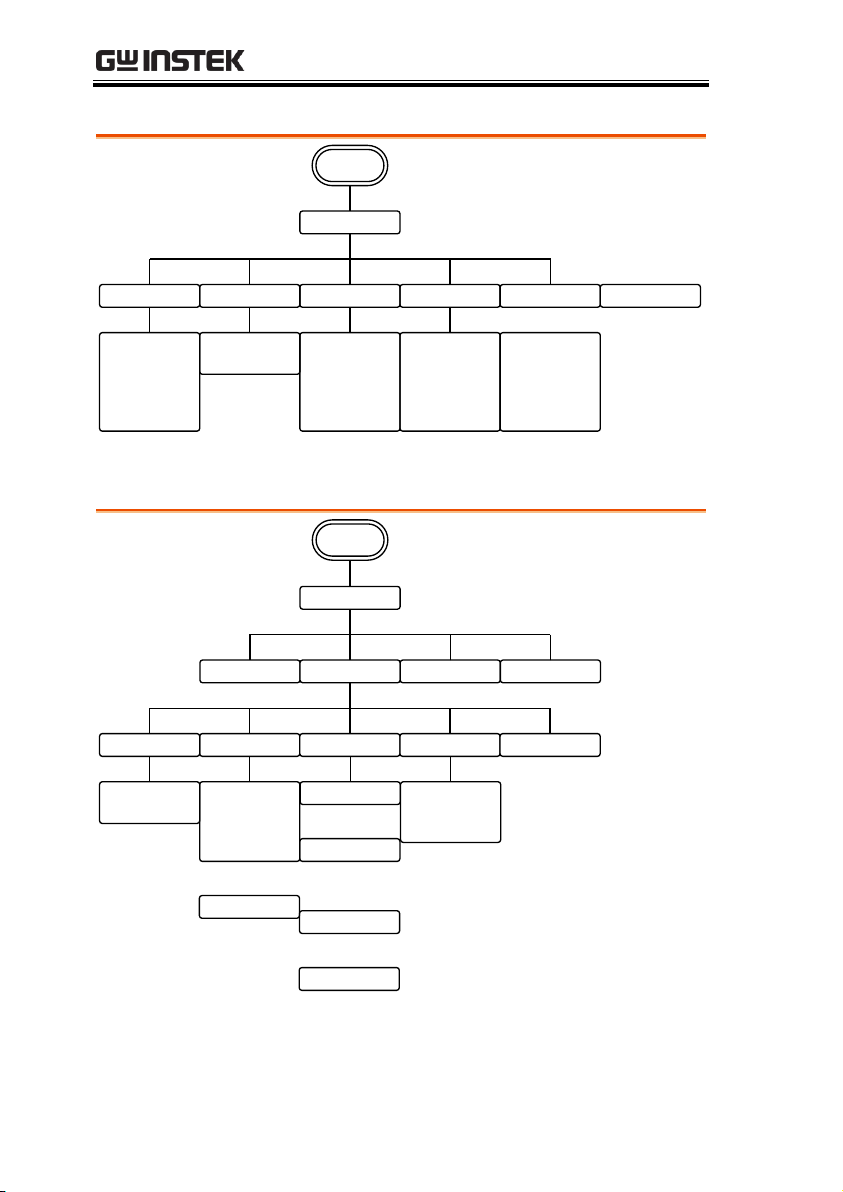
Waveform - Pulse
Waveform
nSEC
uSEC
mSEC
SEC
Return
Width DUTY Rise Fall Edge Time
Pulse
nSEC
uSEC
mSEC
SEC
Return
nSEC
uSEC
mSEC
SEC
Return
nSEC
uSEC
mSEC
SEC
Return
%
Return
Return
Waveform
More
Noise Harmonic DC
Type Order Display
Even
Odd
All
User
Order
mVPP
VPP
Return
Ampl
Phase
Frequency
Time
Return
Total
Enter
Return
Return
Enter
Return
Degree
Return
Return
OFF
ON
Return
Return
Waveform - More
AFG-3021/3022/3031/3032 User Manual
52
Page 53
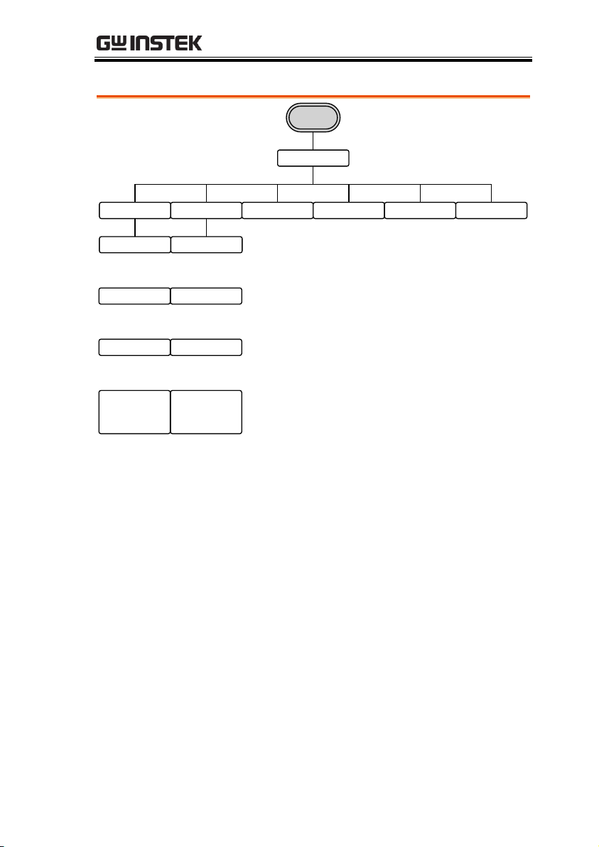
ARB-Display
Horizon Vertical Next Page Back Page Overview Return
Display
ARB
Clear
Enter
Return
Start
Clear
Enter
Return
Length
Clear
Enter
Return
Center
Zoom in
Zoom out
Return
Clear
Enter
Return
Low
Clear
Enter
Return
High
Clear
Enter
Return
Center
Zoom in
Zoom out
Return
QUICK REFERENCE
53
Page 54
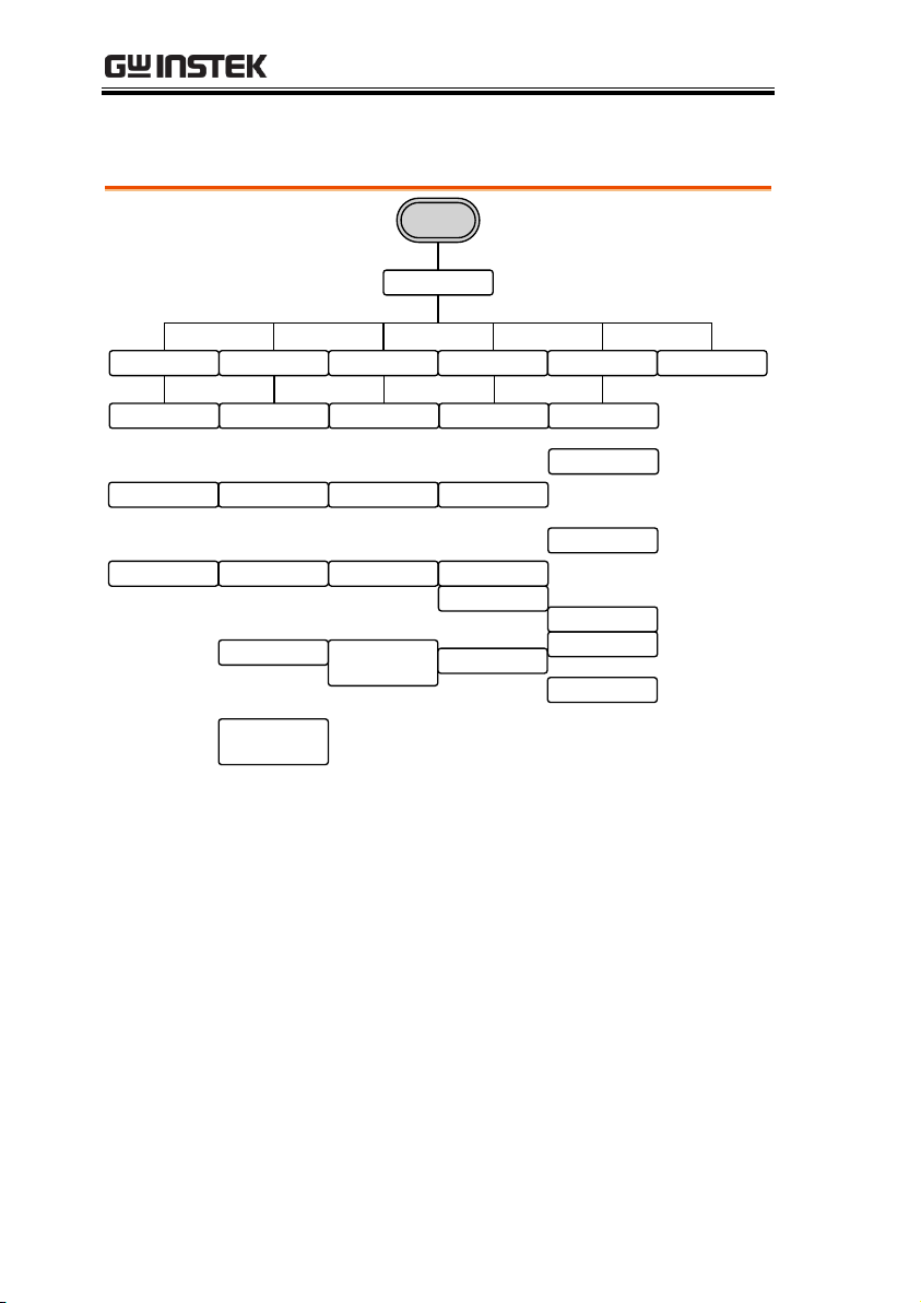
ARB-Edit
Point Line Copy Clear Protect Return
Edit
ARB
Clear
Enter
Return
Address
Clear
Enter
Return
Data
Return
Clear
Enter
Return
Start ADD
Clear
Enter
Return
Start Data
Clear
Enter
Return
Stop ADD
Done
Return
Clear
Enter
Return
Stop Data
Clear
Enter
Return
Start
Clear
Enter
Return
Length
Clear
Enter
Return
Paste To
Done
Return
Clear
Enter
Return
Start
Clear
Enter
Return
Length
Done
All
Done
Return
Return
All
Done
Clear
Enter
Return
Start
Clear
Enter
Return
Length
Done
Unprotect
Done
Return
AFG-3021/3022/3031/3032 User Manual
54
Page 55
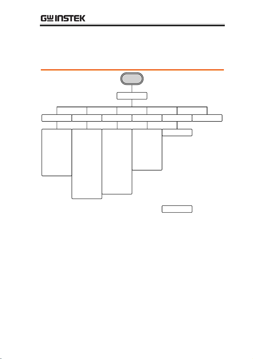
QUICK REFERENCE
Basic Common 1 Common 2 Math More Return
Built in
ARB
Trig
Arccos
Arctan
Sech
Arccot
Arctanh
Sinh
Arccsc
Cosh
Tan
Arcsec
Cot
Tanh
Arcsin
Csc
Arcsinh
Sec
Sine
Square
Ramp
Sinc
Exp Rise
Exp Fall
DC
Pulse
Abstan
Havercosine
Sinever
Abssin
Haversine
Stair_down
Absinehalf
N_pulse
Stair_UD
Ampalt
Negramp
Stair_up
Attalt
Rectpuls1
Stepresp
Diric_even
Roundhalf
Trapezia
Diric_odd
Sawtoot
Tripuls1
Gauspuls1
sinetra
Dlorentz
Ln
Sqrt
Since
Lorentz
Xsquare
Gauss
Window
Barthannwin
Chebwin
Kaiser
Bartlett
Flattopwin
Triang
Blackman
Hamming
Tukeywin
Bohmanwin
hann
ARB-Built-in
Note: The following menu tree only lists where each built-in ARB
waveform is located.
55
Page 56
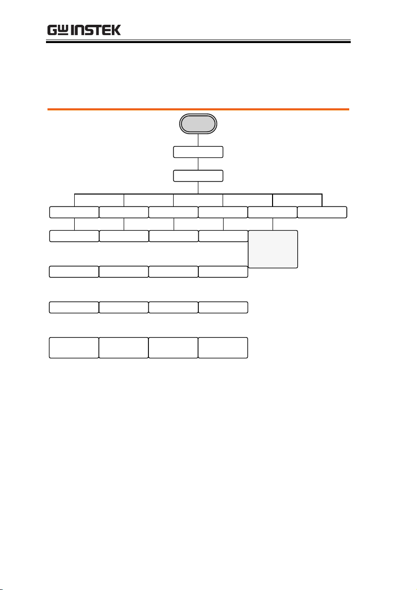
AFG-3021/3022/3031/3032 User Manual
Sine Square Ramp Sinc More Return
Basic
ARB
Clear
Enter
Return
Start
Clear
Enter
Return
Length
Clear
Enter
Return
Scale
Clear
Enter
Return
Start
Clear
Enter
Return
Length
Clear
Enter
Return
Scale
Done
Return
Done
Return
Clear
Enter
Return
Start
Clear
Enter
Return
Length
Clear
Enter
Return
Scale
Done
Return
Clear
Enter
Return
Start
Clear
Enter
Return
Length
Clear
Enter
Return
Scale
Done
Return
Go to ARB
Built in -
Basic –
More menu
Built in
ARB-Built in-Basic
Note: For brevity, only the “Basic” menu tree is listed for the ARB >
Built-in menu tree system. The operation menu keys for all the other
built-in ARB waveforms are mostly identical to the ones listed below.
56
Page 57
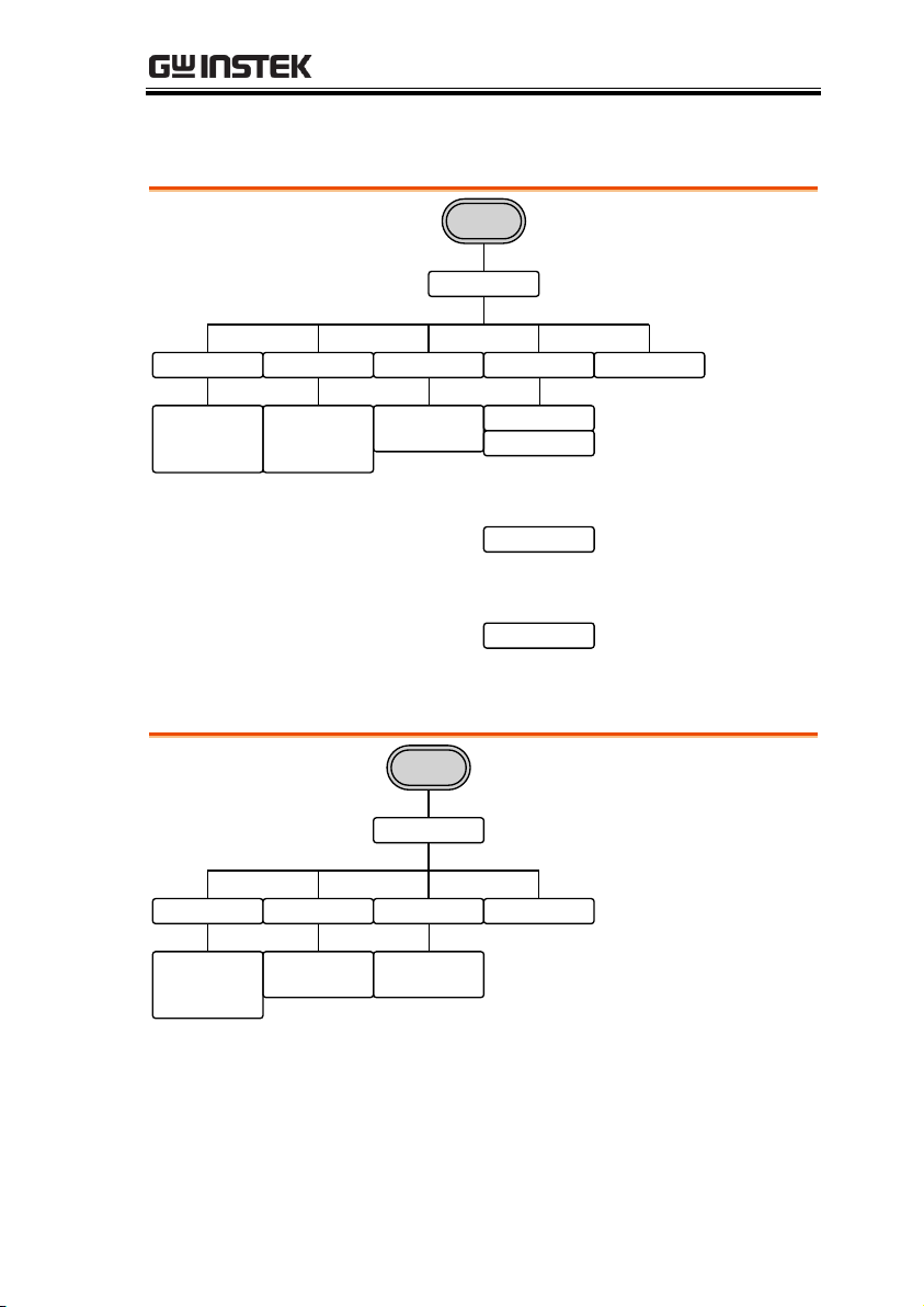
ARB-Save
Start Length Memory USB Return
Save
ARB
Clear
Enter
Return
Select
Return
Clear
Enter
Return
Select
Enter Char
Back Space
Save
Return
New Folder
Enter Char
Back Space
Save
Return
New File
Return
To Memory USB Return
Load
ARB
Clear
Enter
Return
Select
Return
Select
Return
QUICK REFERENCE
ARB-Load
57
Page 58
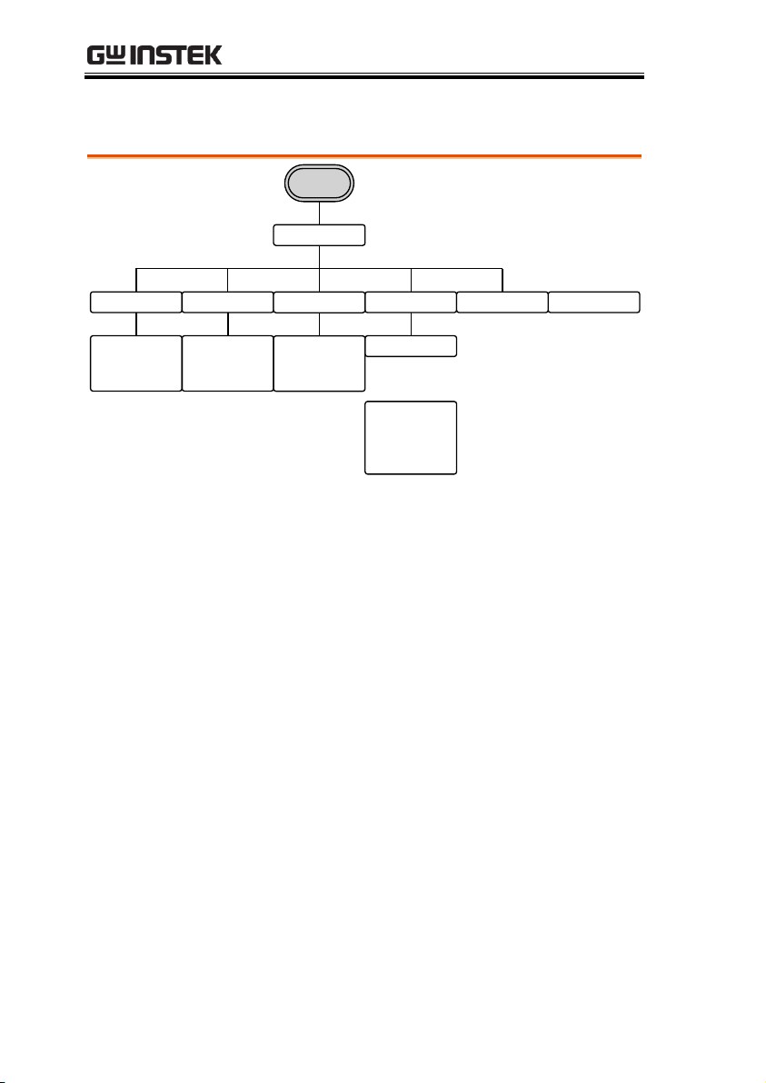
ARB-Output
Output
ARB
Start Length
Clear
Enter
Return
Clear
Enter
Return
N Cycle ReturnInfinite
Clear
Enter
Return
Cycles
EXT
Manual
Trigger
Return
Gate
Pos
Neg
Return
AFG-3021/3022/3031/3032 User Manual
58
Page 59
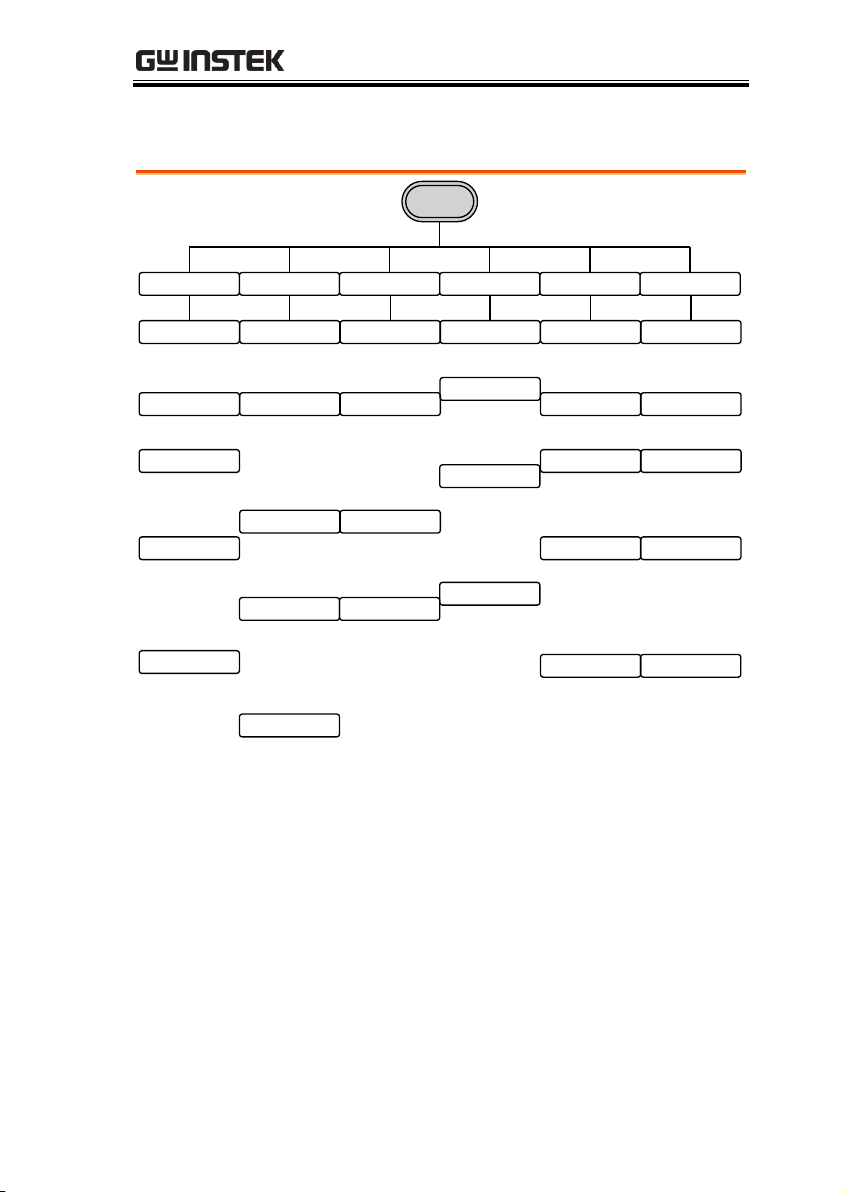
MOD
MOD
INT
EXT
Return
Source
%
Return
Depth
mHz
Hz
kHz
Return
AM Freq
Sine
Square
Triangle
UpRamp
DnRamp
Return
Shape
Return
INT
EXT
Return
Source
%
Return
Duty
mHz
Hz
kHz
Return
PWM Freq
Sine
Square
Triangle
UpRamp
DnRamp
Return
Shape
Return
INT
EXT
Return
Source
uHz
mHz
Hz
kHz
MHz
Return
Hop Freq
FSK Rate
Return
mHz
Hz
kHz
Return
INT
EXT
Return
Source
%
Return
SUM Ampl
Return
Degree
Return
Phase Dev
INT
EXT
Return
Source
uHz
mHz
Hz
kHz
MHz
Return
Freq Dev
mHz
Hz
kHz
Return
FM Freq
Sine
Square
Triangle
UpRamp
DnRamp
Return
Shape
Return
mHz
Hz
kHz
Return
PM Freq
Sine
Square
Triangle
UpRamp
DnRamp
Return
Shape
Return
SUM Freq
mHz
Hz
kHz
Return
Sine
Square
Triangle
UpRamp
DnRamp
Return
Shape
AM PWMFM FSK PM SUM
QUICK REFERENCE
59
Page 60
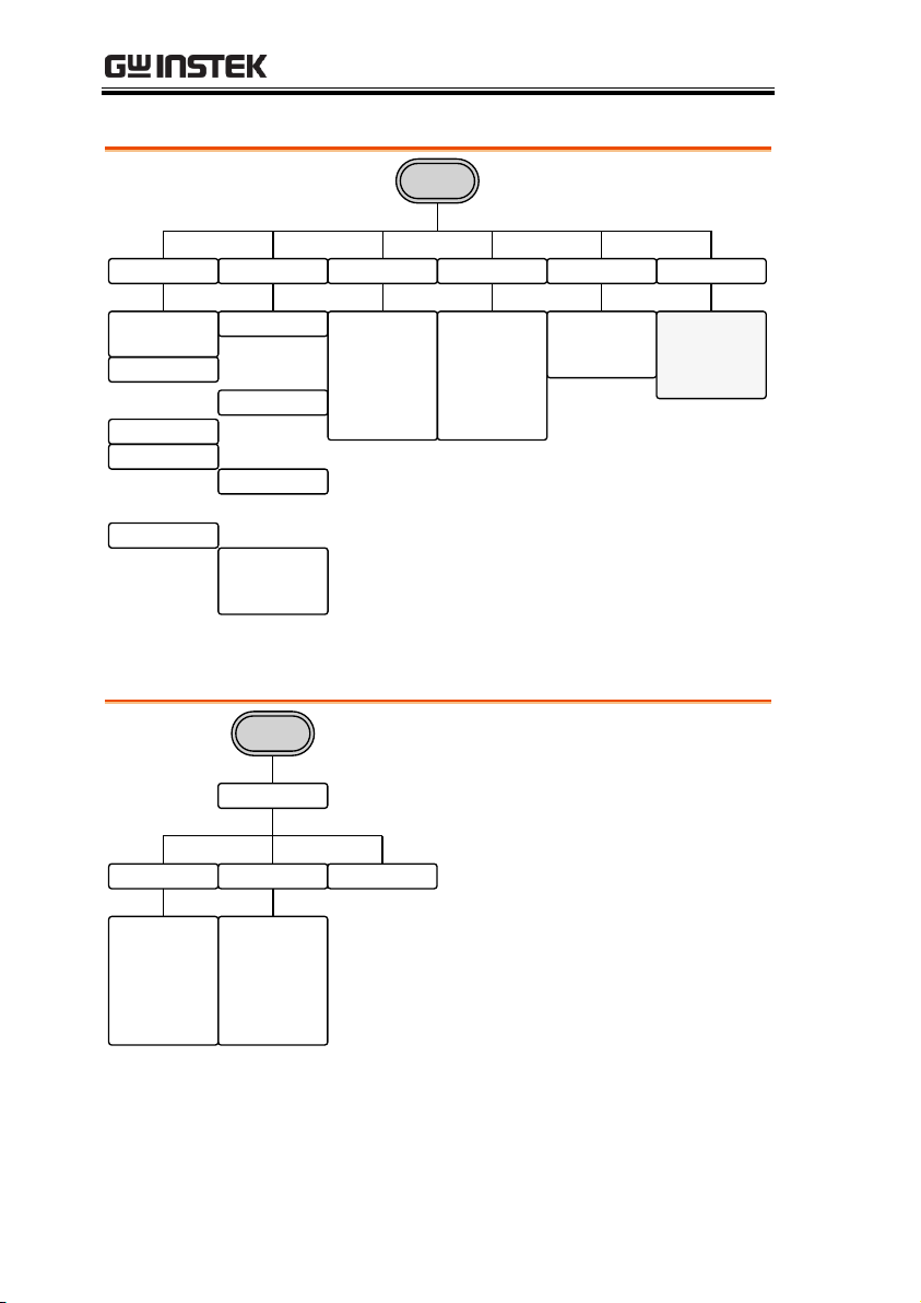
AFG-3021/3022/3031/3032 User Manual
mSEC
SEC
Return
TRIG Type Type/MOD Start Stop SWP Time More
SWEEP
INT
EXT
uHz
mHz
Hz
kHz
MHz
Return
uHz
mHz
Hz
kHz
MHz
Return
Go to the
Sweep -
Frequency -
More menu
Manual
Trigger
Return
OFF
mSEC
SEC
Return
TRIG Time
Return
Freq
Ampl
Return
Type
Mode
Cont
Gate
Return
Functions
Linear
Log
Return
Sawtooth
Triangle
Return
More
Sweep
Span Center Return
uHz
mHz
Hz
kHz
MHz
Return
uHz
mHz
Hz
kHz
MHz
Return
Sweep - Type/MOD = Frequency
Sweep - More
60
Page 61
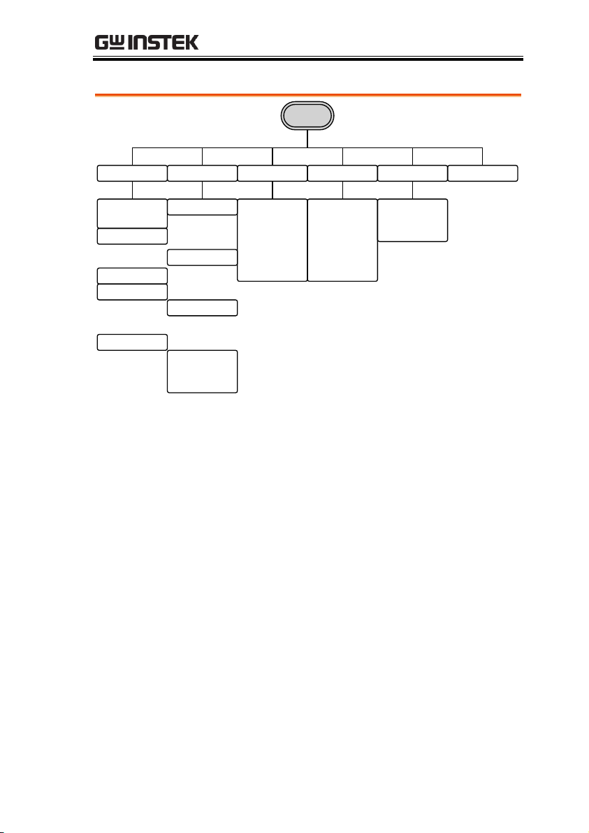
Sweep - Type/MOD = Amplitude
mSEC
SEC
Return
TRIG Type Type/MOD Start Stop SWP Time Return
SWEEP
INT
EXT
dBm
mVRMS
VRMS
mVPP
VPP
Return
dBm
mVRMS
VRMS
mVPP
VPP
Return
Manual
Trigger
Return
OFF
mSEC
SEC
Return
TRIG Time
Return
Freq
Ampl
Return
Type
Mode
Cont
Gate
Return
Functions
Linear
Log
Return
Sawtooth
Triangle
Return
QUICK REFERENCE
61
Page 62
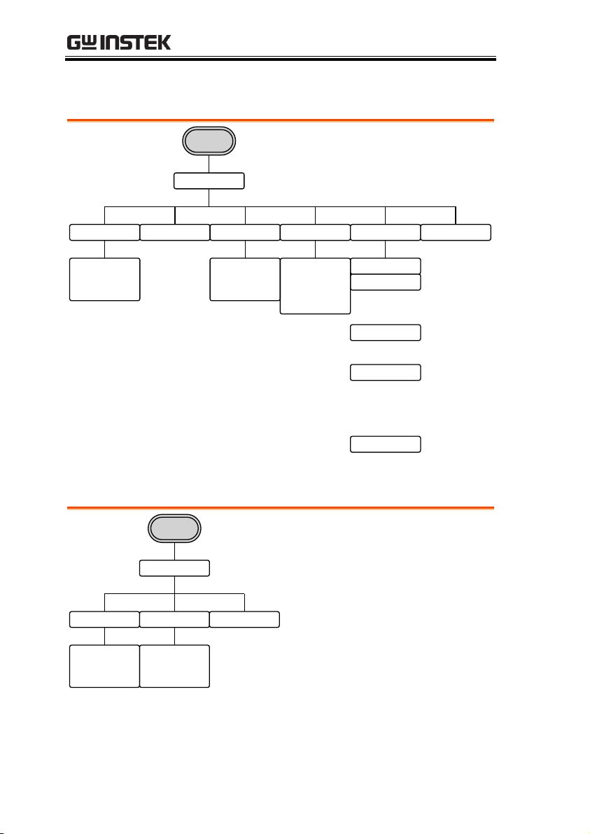
Burst – N Cycle
Cycles Infinite Phase Period
Clear
Cyc
Return
N Cycle
Burst
TRIG Setup Return
Clear
Degree
Return
uSEC
mSEC
SEC
Return
Int
Rise
Fall
Return
EXT
Trigger
Return
Manual
nSEC
uSEC
mSEC
SEC
Return
Delay
Return
Polarity Phase Return
Pos
Neg
Return
Gate
Burst
Clear
Degree
Return
AFG-3021/3022/3031/3032 User Manual
Burst - Gate
62
Page 63
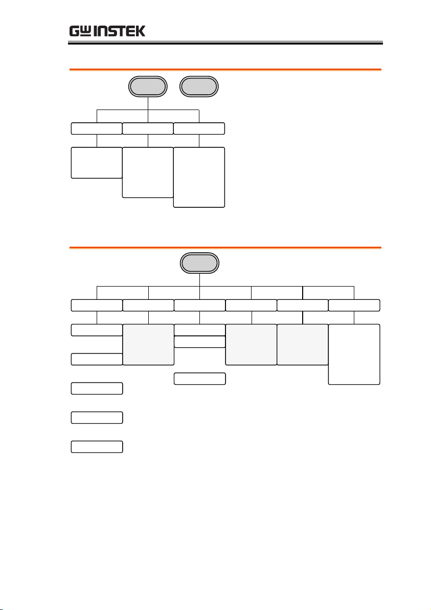
QUICK REFERENCE
Load Phase DSO-Link
50 OHM
High Z
Return
CH1
0 Phase
Sync Int
Degree
Align Phase
Return
Search
CH1
CH2
CH3
CH4
Return
CH2
/
UTIL
Memory Interface Cal. Load System
Done
Return
Store
Done
Return
Recall
Delete
Self Test
Version
Upgrade
Return
Software
Return
Done
Return
Delete All
Done
Return
Go to the
UTIL –
Interface
menu
Return
50 OHM
High Z
Return
Go to the
UTIL –
System
menu
DSO-Link
Search
CH1
CH2
CH3
CH3
Return
CH1 / CH2 (AFG-3022/AFG-3032 Only)
UTIL (AFG-3021/3031)
63
Page 64
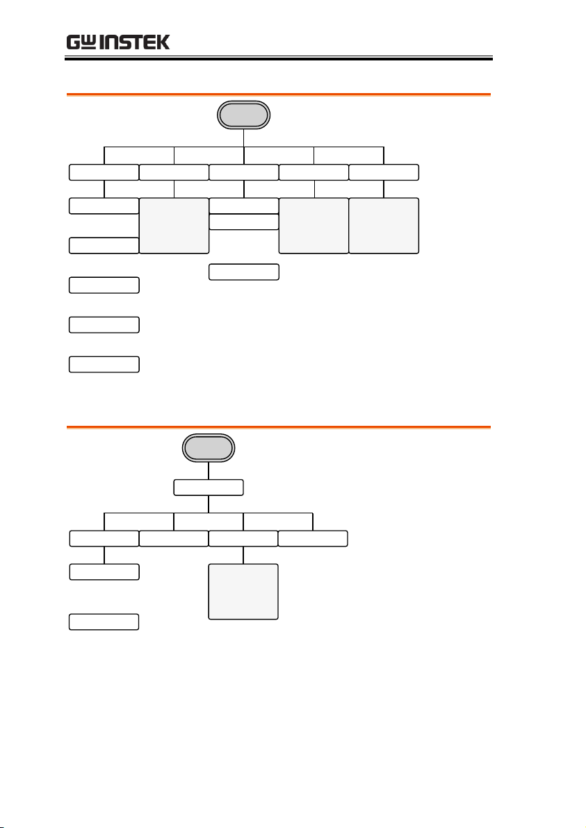
AFG-3021/3022/3031/3032 User Manual
UTIL
Memory Interface Cal. System Dual Ch
Done
Return
Store
Done
Return
Recall
Delete
Self Test
Version
Upgrade
Return
Software
Return
Done
Return
Delete All
Done
Return
Go to the
UTIL –
Interface
menu
Return
Go to the
UTIL –
System
menu
Go to the
UTIL – Dual
Ch menu
GPIB USB LAN Return
Clear
Done
Return
Address
Return
Interface
UTIL
Go to the
UTIL –
Interface -
LAN menu
UTIL (AFG-3022/AFG-3032)
UTIL - Interface
64
Page 65
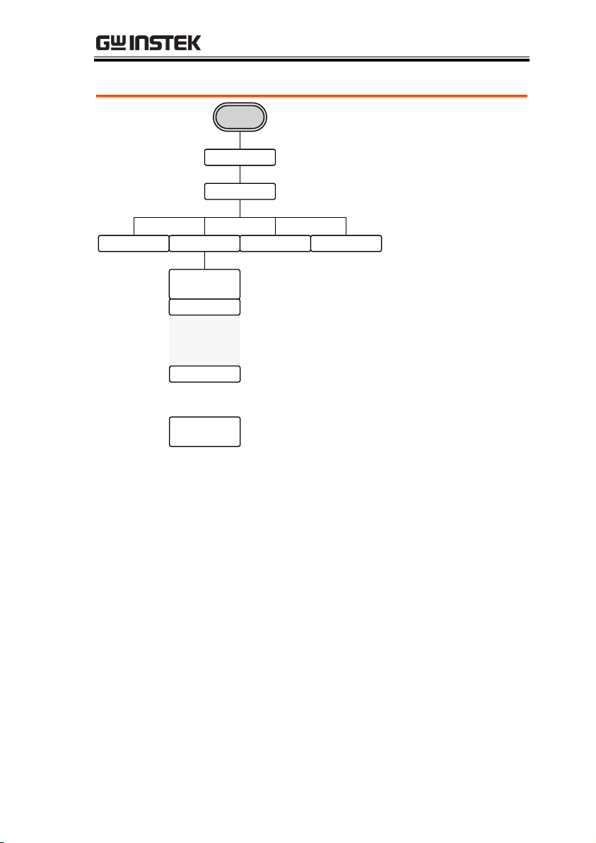
QUICK REFERENCE
Go To
UTIL – Interface
– LAN Config –
Manual menu
Interface
UTIL
LAN
Remote Config Done Return
DHCP
Auto IP
Manual
Enter Char
Done
Return
Host Name
Done
Return
UTIL - Interface - LAN
65
Page 66
AFG-3021/3022/3031/3032 User Manual
Interface
UTIL
LAN
Config
Manual
IP Addr NetMask Gateway Done
Done
Clear
Return
Return
Done
Clear
Return
Done
Clear
Return
簡體中文
English
繁體中文
Return
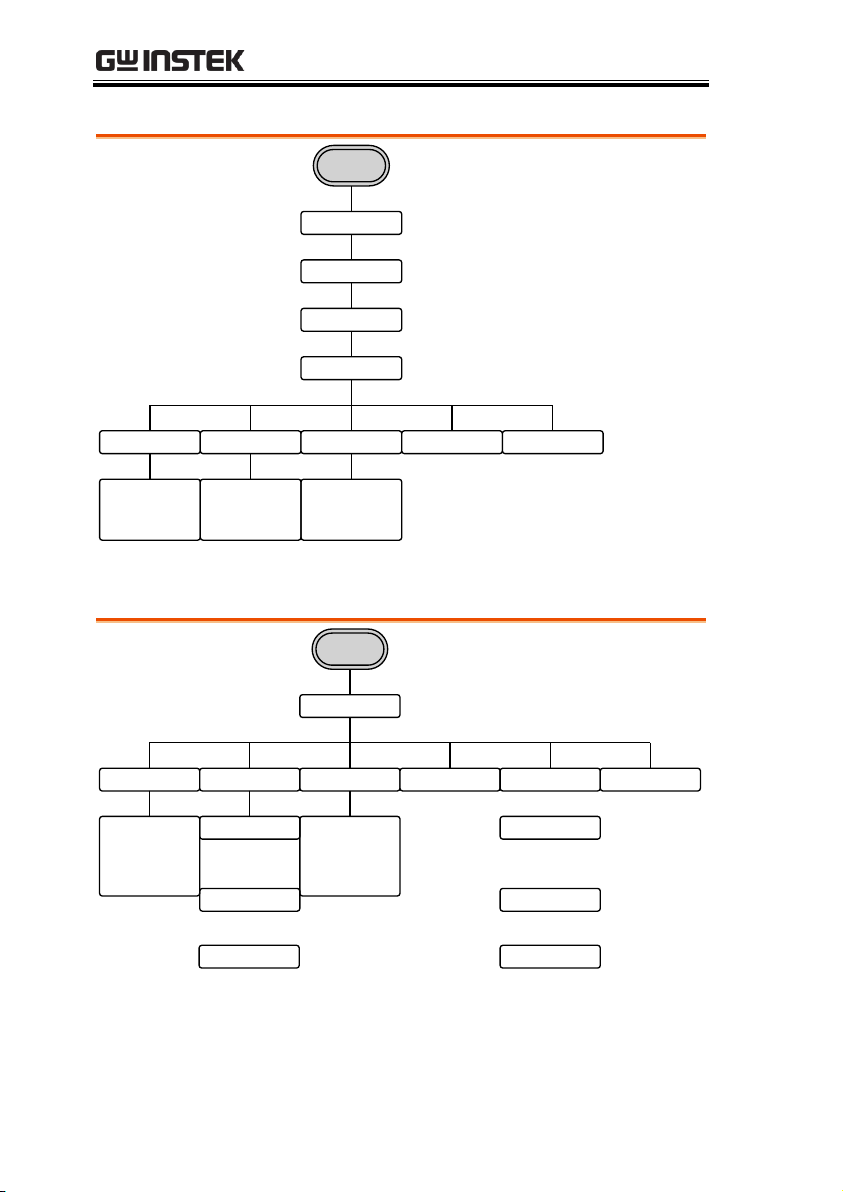
Language Display Opt. Clk Source Beep More
INT
EXT
EXT Sync
Return
Suspend
ON
Return
Display
Brightness
Return
Enter
Return
System
UTIL
Return
Last
Default
Return
Power ON
Help
Select
Return
Single
Dual
Return
Display
UTIL - Interface - LAN - Config - Manual
UTIL - System
66
Page 67
QUICK REFERENCE
Freq Cpl Ampl Cpl Tracking Return
OFF
ON
Inverted
Return
ON
OFF
Return
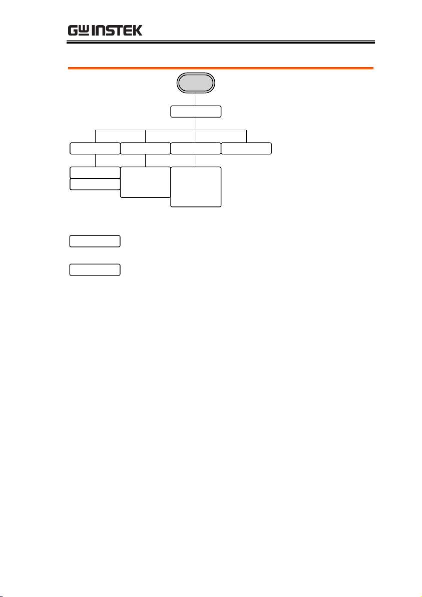
Dual Ch
UTIL
uHz
mHz
Hz
kHz
MHz
Return
Offset
Ratio
OFF
Return
Enter
Return
UTIL - Dual Channel
67
Page 68
AFG-3021/3022/3031/3032 User Manual
Here are the default panel settings which appear
when pressing the Preset key.
Preset
Output Config.
Function
Sine wave
Frequency
1kHz
Amplitude
3.000 Vpp
Offset
0.00V dc
Output units
Vpp
Output terminal
50Ω
Modulation
(AM/FM/FSK)
Carrier Wave
1kHz Sine wave
Modulation waveforms
100Hz Sine wave
AM Depth
100%
FM Deviation
100Hz
FSK Hop Frequency
100Hz
FSK Frequency
10Hz
PWM Duty
50%
PWM Frequency
20kHz
Modem Status
Off
Sweep
Start/Stop frequency
100Hz/1kHz
Sweep time
1s
Start/Stop amplitude
1.000/3.000 Vpp
Sweep function
Linear
Sweep status
Off
Default Settings
68
Page 69

QUICK REFERENCE
Burst
Burst Frequency
1kHz
Ncycle
1
Burst period
10ms
Burst starting phase
0˚
Burst status
Off
Trigger
Trigger source
Internal (immediate)
Interface config.
GPIB Address
10
Interface
USB
LAN
DHCP
Calibration
Calibration Menu
Restricted
69
Page 70

AFG-3021/3022/3031/3032 User Manual
Select a Channel ................................................................ 71
CH1/CH2 ............................................................................. 71
Select a Waveform ............................................................. 72
Sine Wave ............................................................................. 72
Setting a Square Wave ......................................................... 73
Triangle Wave ....................................................................... 74
Setting the Pulse Width ....................................................... 75
Setting the Pulse Rise & Fall Time ...................................... 76
Setting the Pulse Edge Time ................................................ 77
Setting the Pulse Duty Time ................................................ 78
Setting a Ramp ..................................................................... 79
Noise Wave .......................................................................... 80
Harmonic Wave ................................................................... 80
Harmonic Order .................................................................. 81
Harmonic Characteristics .................................................... 83
DC Wave ............................................................................... 84
Setting the Waveform Frequency ........................................ 85
Setting the Amplitude .......................................................... 87
Setting the DC Offset ........................................................... 88
OPERATION
The Operation chapter shows how to output basic waveform
functions. For details on modulation, sweep, burst and arbitrary
waveforms, please see the Modulation and Arbitrary waveform
chapters on pages 89 and 174. For information on the dual channel
and multi-unit operation, please see page 178 & 186, respectively.
70
Page 71
OPERATION
Panel Operation
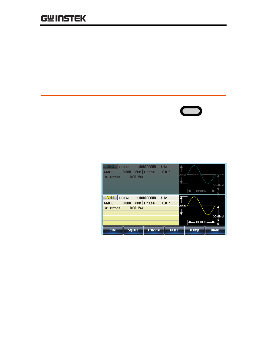
1. Press the CH1 or CH2 key.
CH1
2. The selected channel will be visible while the
deselected channel will be dimmed.
In the screen shot below, CH1 is selected.
Select a Channel
As the AFG-3022 or AFG-3032 are dual channel models, the desired
output channel must first be selected before assigning the operation
for that channel.
CH1/CH2
71
Page 72
AFG-3021/3022/3031/3032 User Manual
Panel Operation
1. Press the Waveform key.
Waveform
2. Press F1 (Sine).
Sine
F 1
Select a Waveform
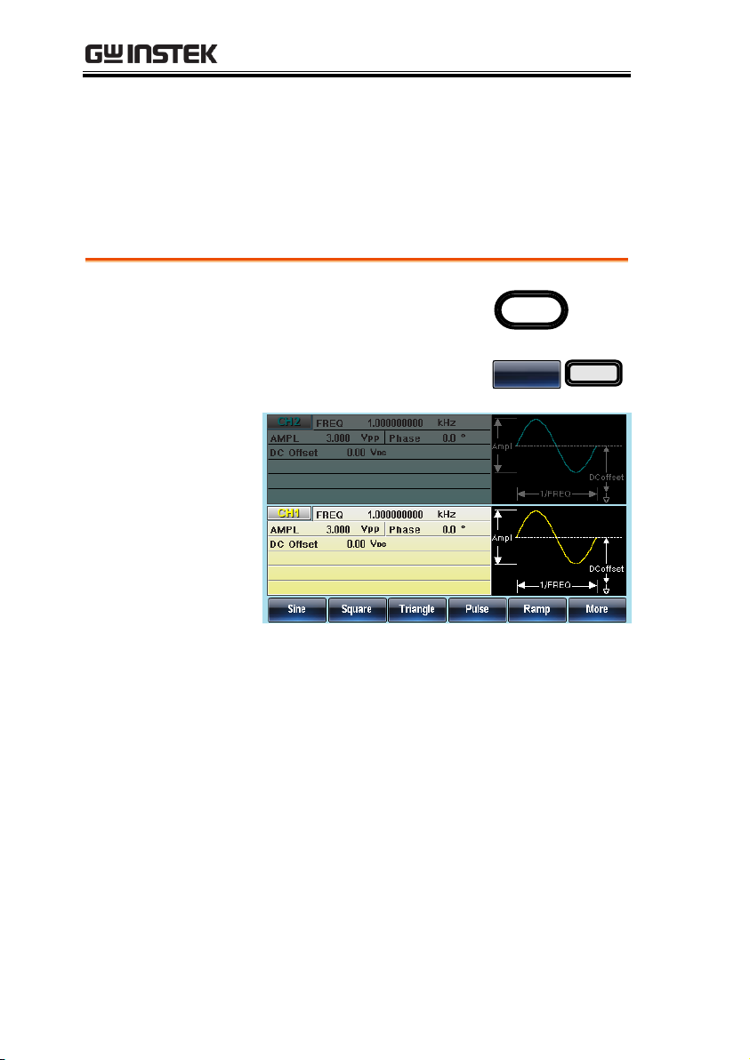
The AFG-30XX can output 8 standard waveforms: sine, square,
triangle, pulse, ramp, noise, harmonic and DC waveforms.
Sine Wave
72
Page 73
OPERATION
Panel Operation
1. Press the Waveform key.
Waveform
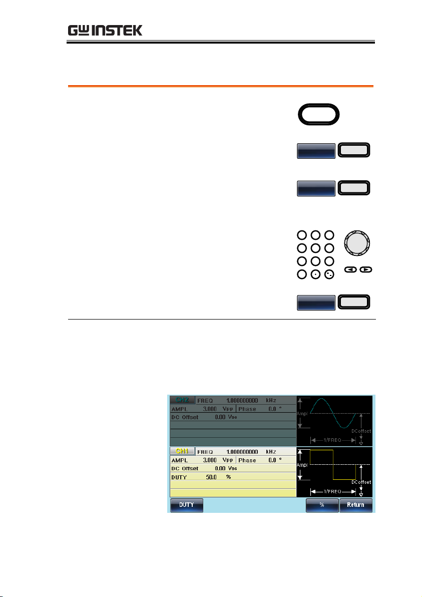
2. Press F2 (Square) to create a
square waveform.
Square
F 2
3. Press F1 (Duty). The Duty
parameter will be highlighted
in the parameter window.
DUTY
F 1
4. Use the selector keys and
scroll wheel or number pad
to enter the Duty range.
0
/
321
4
7 859
6
5. Press F5 (%) to choose %
units.
%
F 5
Range
Frequency
Duty Range
≤25MHz
(20MHz AFG-3021/3022)
20%~80%
25MHz~≤30MHz
40%~60%
Setting a Square Wave
73
Page 74
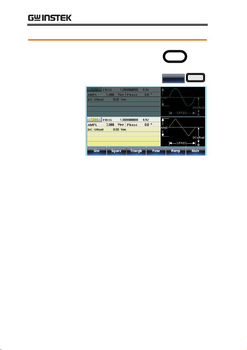
Triangle Wave
Panel Operation
1. Press the Waveform key.
Waveform
2. Press F3 (Triangle).
Triangle
F 3
AFG-3021/3022/3031/3032 User Manual
74
Page 75
OPERATION
Fall timeRise time
Pulse Width
Period
50%
90%
10%
90%
50%
10%
Panel Operation
1. Press the Waveform key.
Waveform
2. Press F4 (Pulse) to create a
pulse waveform.
Pulse
F 4
3. Press F1 (Width). The Width
parameter will be highlighted
in the parameter window.
Width
F 1
4. Use the selector keys and
scroll wheel or number pad
to enter the pulse width.
0
/
321
4
7 859
6
Setting the Pulse Width
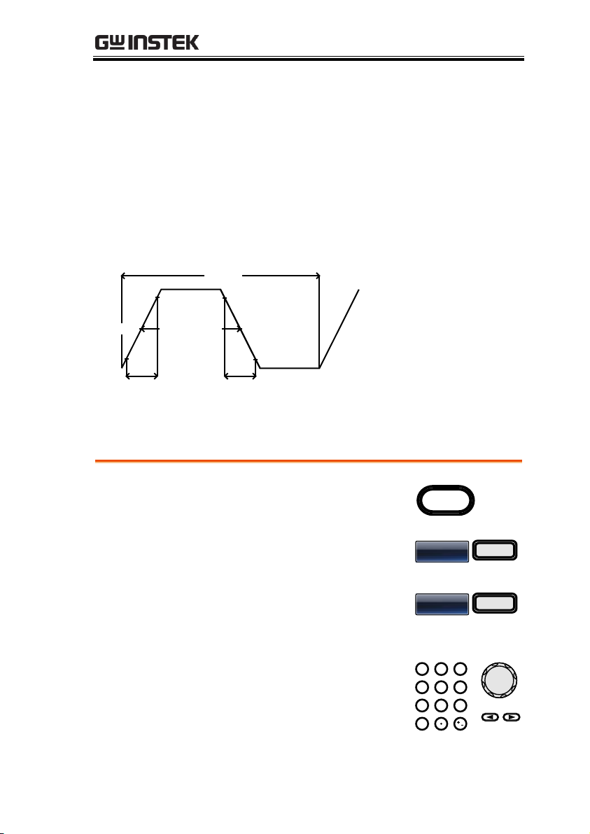
The pulse width settings depend on the rise & fall time settings or
the edge time setting and the period settings, as defined below:
Pulse Width - 0.625 * [(Rise Time - 0.6nS) + (Fall Time - 0.6nS)] ≧ 0
Period ≧ Pulse Width+ 0.625 * [(Rise Time - 0.6nS)+(Fall Time -
0.6nS)]
Pulse width is defined as the time from the 50% rising edge
threshold to the 50% falling edge threshold of one full period.
See page 76 to set the rise and fall time settings and page 77 for the
edge time settings. Alternatively, instead of setting the pulse width,
the pulse duty can be set, see page 78 for details.
75
Page 76
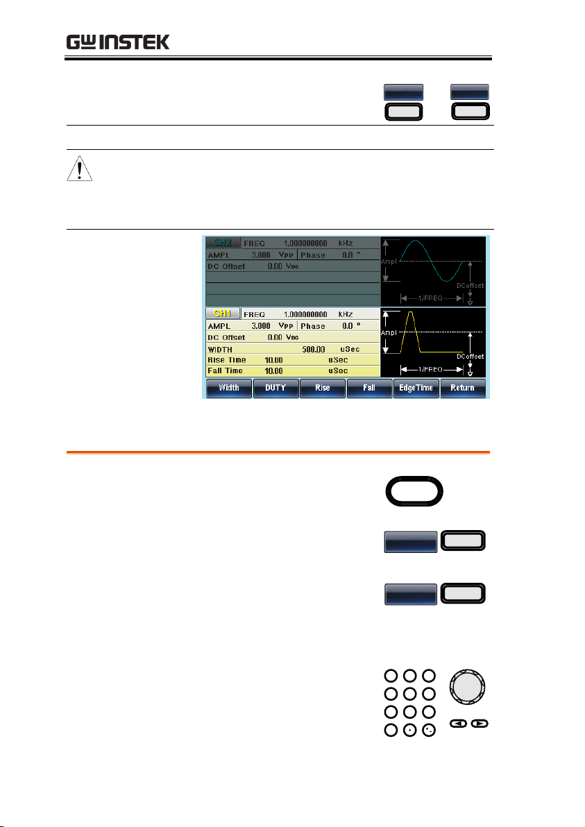
AFG-3021/3022/3031/3032 User Manual
5. Press F2~F5 choose the unit
range.
nSEC
F 2
~
SEC
F 5
Range
Pulse Width
20ns~999.83ks
Note
Resolution:
Freq < 25MHz
(20MHz AFG-3021/3022): 0.01ns
pulse width (or 3 digit resolution)
Freq < 8.5 kHZ: 0.0001% duty cycle
Panel Operation
1. Press the Waveform key.
Waveform
2. Press F4 (Pulse) to create a
pulse waveform.
Pulse
F 4
3. Press F3 (Rise) or F4 (Fall).
The Rise or Fall parameter
will be highlighted in the
parameter window.
Rise
F 3
4. Use the selector keys and
scroll wheel or number pad
to enter the rise or fall time.
0
/
321
4
7 859
6
Setting the Pulse Rise & Fall Time
76
Page 77
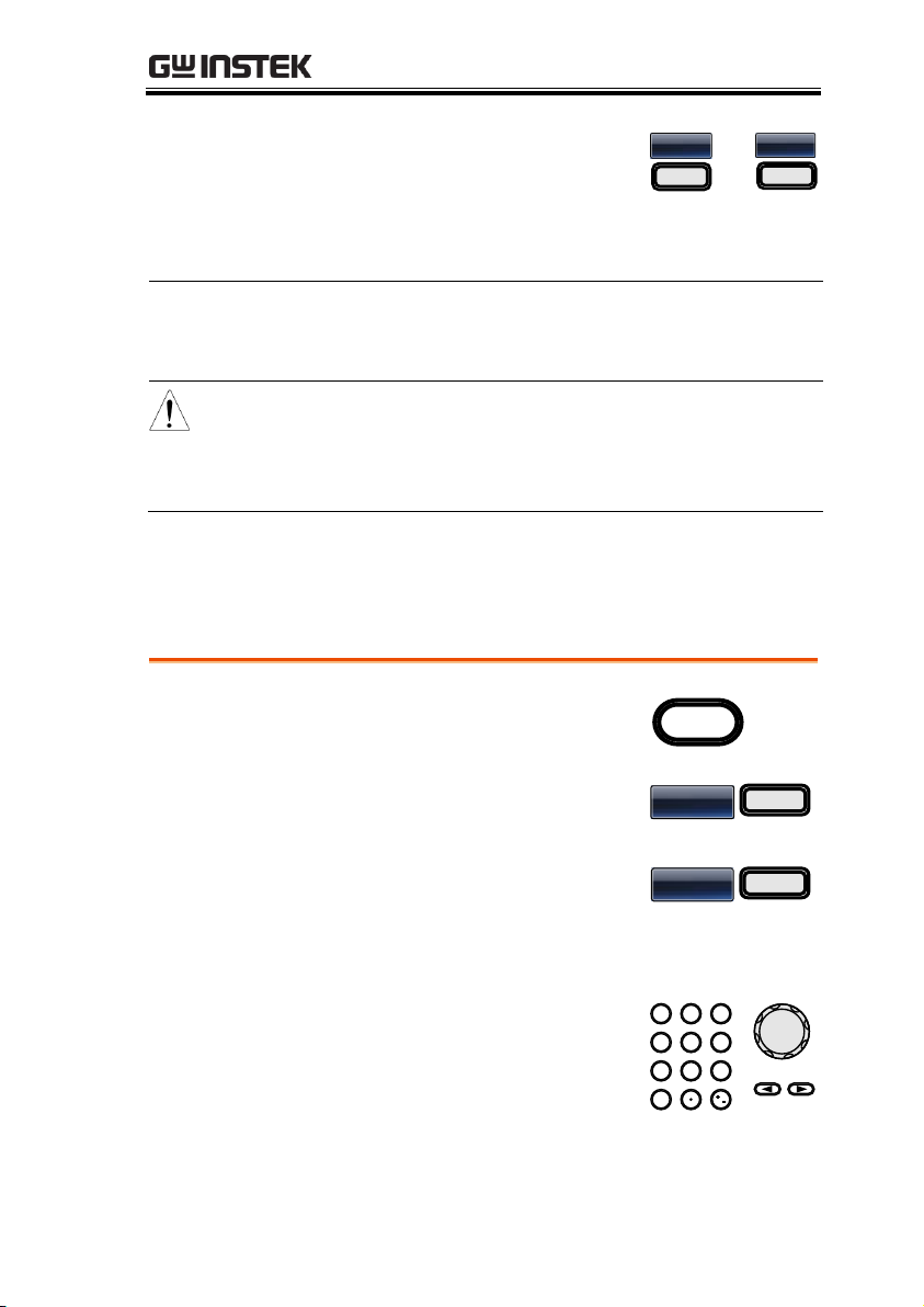
OPERATION
5. Press F2~F5 to choose the
unit range.
nSEC
F 2
~
SEC
F 5
6. Repeat the above steps for the opposite edge
time.
Range
Minimum
rise/fall time:
9.32ns ~ 799.9ks
Note
Duty
Considerations:
Width - 0.625 * [(Rise Time -
0.6nS) + (Fall Time - 0.6nS)] ≧ 0
Period ≧ Width+ 0.625 * [(Rise
Time - 0.6nS)+(Fall Time - 0.6nS)]
Panel Operation
1. Press the Waveform key.
Waveform
2. Press F4 (Pulse) to create a
pulse waveform.
Pulse
F 4
3. Press F5 (Edge Time). The
Edge Time parameter will be
highlighted in the parameter
window.
Edge Time
F 5
4. Use the selector keys and
scroll wheel or number pad
to enter the edge time.
0
/
321
4
7 859
6
Setting the Pulse Edge Time
The edge time sets the rise and fall time to the same value. The edge
time setting can affect the settable pulse width time.
77
Page 78
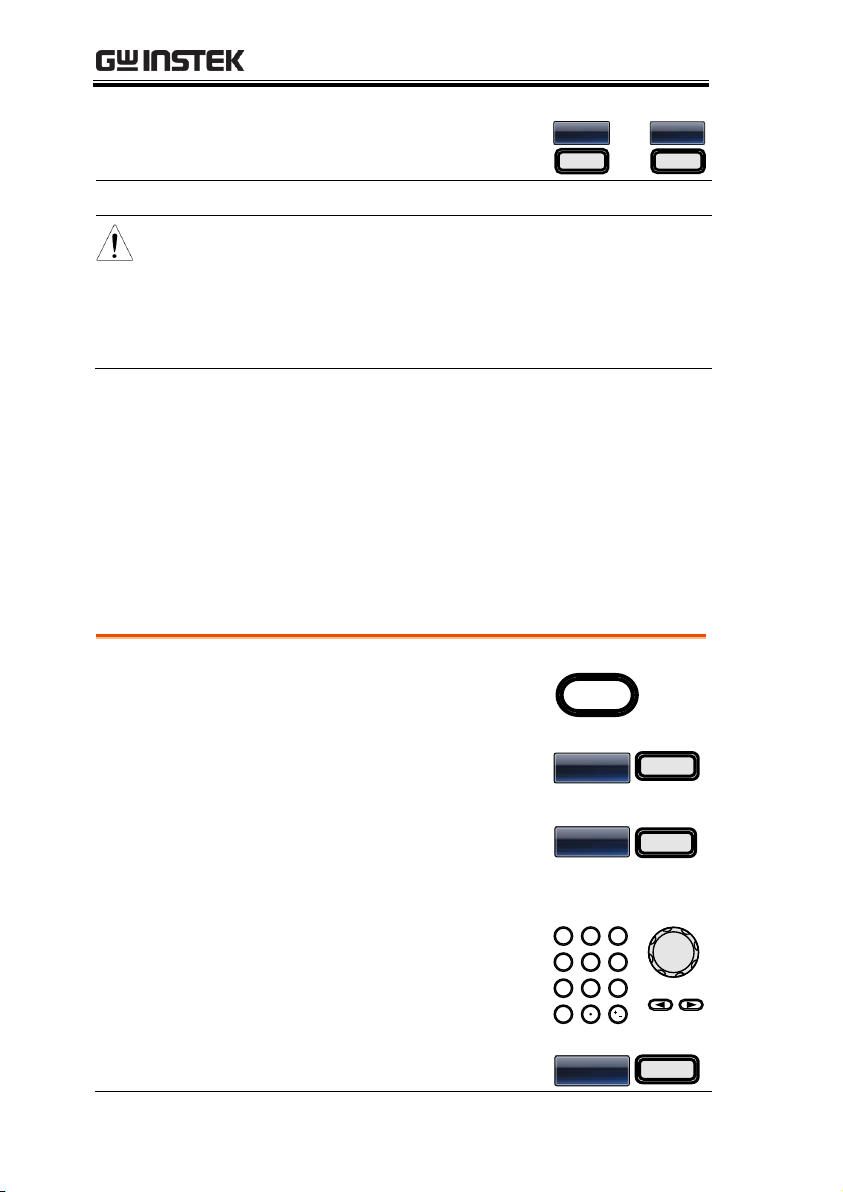
AFG-3021/3022/3031/3032 User Manual
5. Press F2~F5 to choose the
unit range.
nSEC
F 2
~
mSEC
F 5
Range
Edge Time Range
9.32ns~799.9ks
Note
Duty
Considerations:
Width - 1.25 *
(Edge Time - 0.6nS) ≧ 0
Period≧Pulse Width +
1.25*(Edge time -0.6ns)
0.0001% duty cycle resolution
Panel Operation
1. Press the Waveform key.
Waveform
2. Press F4 (Pulse) to create a
pulse waveform.
Pulse
F 4
3. Press F2 (DUTY). The DUTY
parameter will be highlighted
in the parameter window.
DUTY
F2
4. Use the selector keys and
scroll wheel or number pad
to enter the duty time.
0
/
321
4
7 859
6
5. Press F1 to choose the % unit.
%
F 1
Setting the Pulse Duty Time
Instead of setting the pulse width of the pulse, the duty of the pulse
can be set. The settable duty times depend on the rise & fall time
settings, as defined below:
Duty ≧ 0.625×100×[rise time - 0.6ns +fall time - 0.6ns]/period
Or
Duty ≦ 100 - {62.5×[(rise time - 0.6ns) + (fall time - 0.6ns)]/period}
78
Page 79
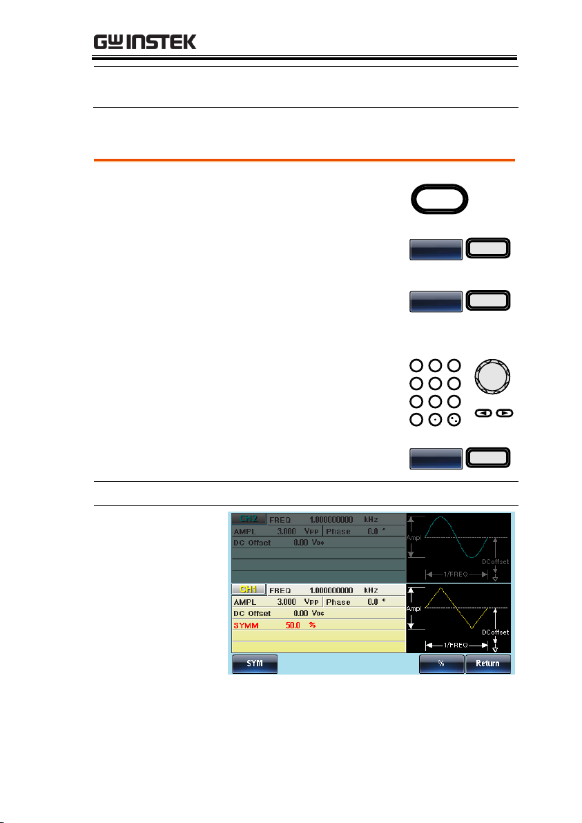
OPERATION
Range
Duty Range
0.0170%~99.983%
Resolution 0.0001%
Panel Operation
1. Press the Waveform key.
Waveform
2. Press F5 (Ramp) to create a
ramp waveform.
Ramp
F 5
3. Press F1 (SYM). The SYM
parameter will be highlighted
in the parameter window.
SYM
F 1
4. Use the selector keys and
scroll wheel or number pad
to enter the symmetry
percentage.
0
/
321
4
7 859
6
5. Press F5 (%) to choose %
units.
%
F 5
Range
Symmetry
0%~100%
Setting a Ramp
79
Page 80
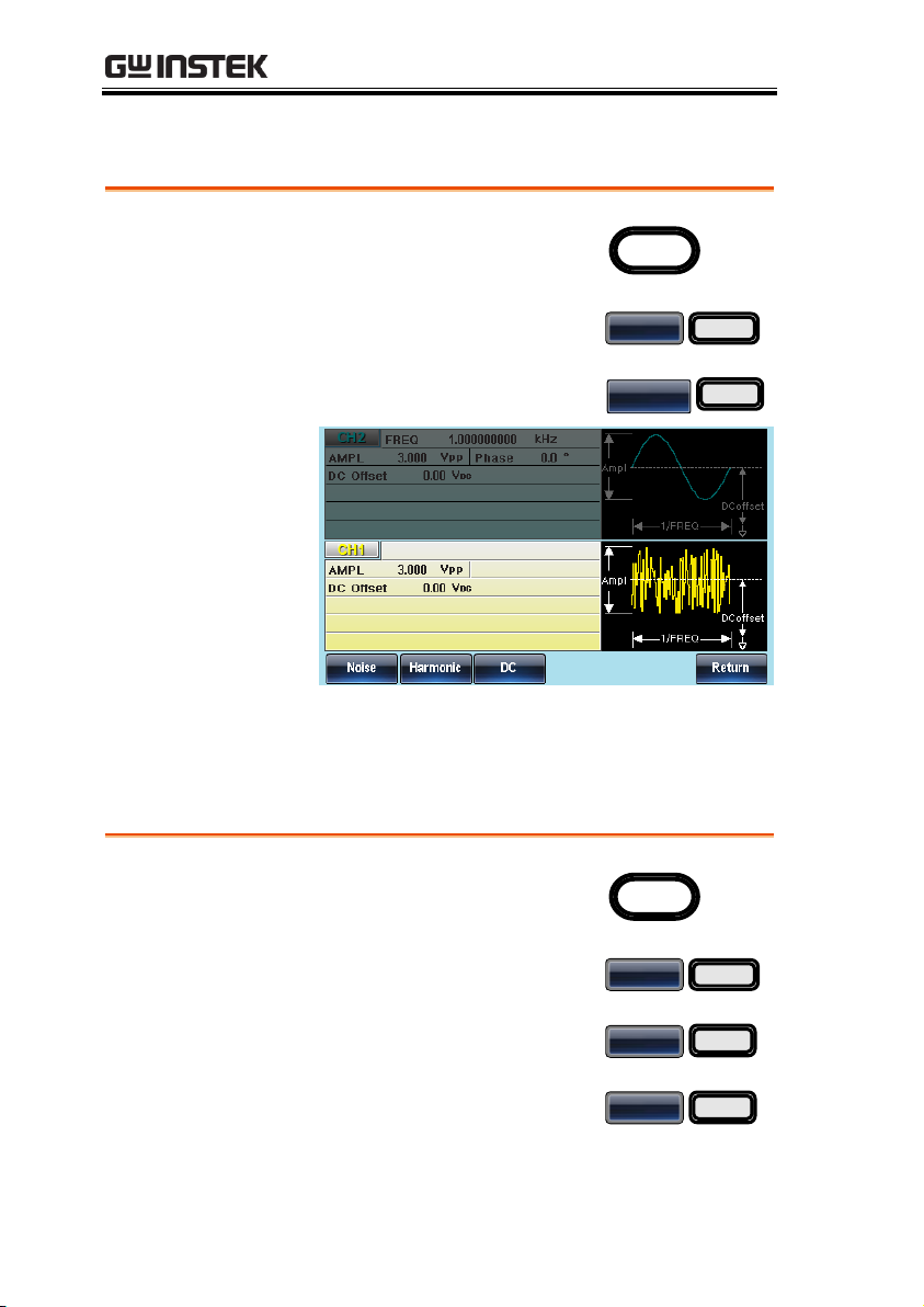
Noise Wave
Panel Operation
1. Press the Waveform key.
Waveform
2. Press F6 (More).
More
F 6
3. Press F1 (Noise).
Noise
F 1
Panel Operation
1. Press the Waveform key.
Waveform
2. Press F6 (More).
More
F 6
3. Press F2 (Harmonic).
Harmonic
F2
4. Press F1 (Total) to choose the
total number of harmonics.
This includes the
fundamental harmonic.
Total
F1
AFG-3021/3022/3031/3032 User Manual
Harmonic Wave
The harmonic wave function creates a harmonic sine wave with a
designated number of harmonics.
80
Page 81
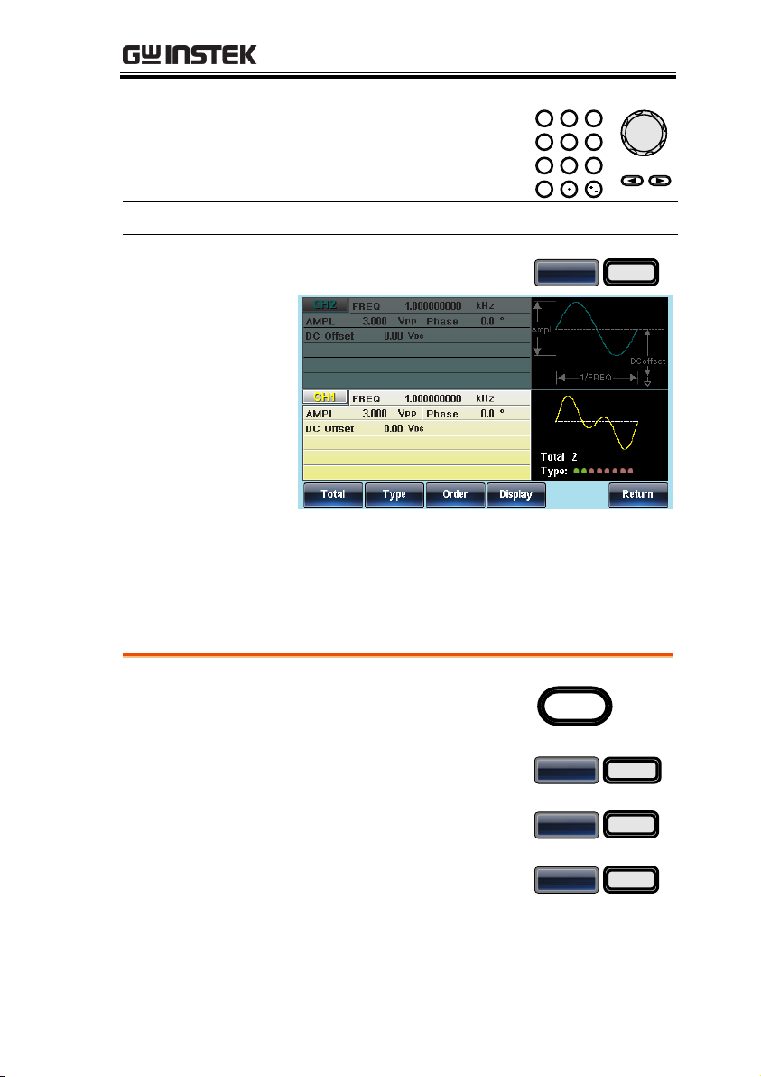
OPERATION
5. Use the selector keys and
scroll wheel or number pad
to enter the number of
harmonics.
0
/
321
4
7 859
6
Range
Number of harmonics
2 ~ 8
6. Press F1 (Enter).
Enter
F1
Panel Operation
1. Press the Waveform key.
Waveform
2. Press F6 (More).
More
F 6
3. Press F2 (Harmonic).
Harmonic
F2
4. Press F2 (Type).
Type
F2
Harmonic Order
After the total number of harmonics has been selected(above), you
can also select which harmonic orders are used: odd, even, all or a
user-defined set.
81
Page 82
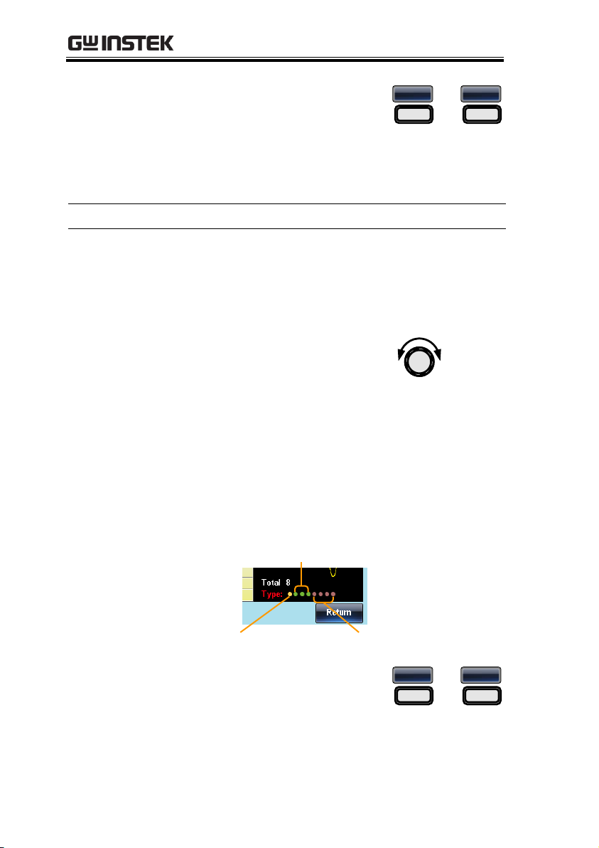
AFG-3021/3022/3031/3032 User Manual
5. Press F1 ~ F4 to chose which
harmonic orders to include in
the resultant harmonic
waveform.
Even
F1
~
User
F4
Note: You may have to wait a short while for
the meter to process the waveform.
Range
Harmonic
Even, Odd, ALL, User
Selecting UserDefined Orders
1. If User was chosen, each order can be
individually selected or deselected.
2. Turn the User defined orders on or off:
Turn the scroll wheel to
move the cursor to the
desired order in the “Type”
parameter on the waveform
display screen.
Selected orders are shown as green dots.
Deselected orders are shown as grey dots.
The cursor is shown as a yellow dot.
Orders are shown from 1
st
(left side) to 8th
(right side).
Selected orders
Cursor
Deselected orders
Order
<1st, 2nd, 3rd, 4th, 5th, 6th, 7th, 8th >
3. Turn the selected order on or
off using the F1 or F2 softkeys.
OFF
F1
ON
F2
82
Page 83
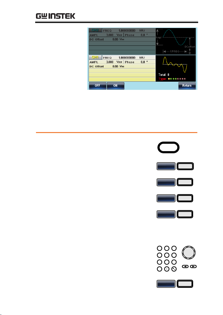
OPERATION
Panel Operation
1. Press the Waveform key.
Waveform
2. Press F6 (More).
More
F 6
3. Press F2 (Harmonic).
Harmonic
F2
4. Press F3 (Order).
Order
F3
5. Press F1 (Order).
Order
F1
6. The Order parameter will become highlighted
in red.
7. Use the selector keys and
scroll wheel or number pad
to select an order.
0
/
321
4
7 859
6
8. Press F5 (Enter).
Enter
F5
Harmonic Characteristics
The amplitude and phase of each harmonic order can individually
set. By default the amplitude is the same as the fundamental
frequency and the phase is set to 0º.
83
Page 84
AFG-3021/3022/3031/3032 User Manual
9. Press F2 (Amplitude).
Amplitude
F2
10. Use the selector keys and
scroll wheel or number pad
to set the amplitude of
previously selected order.
0
/
321
4
7 859
6
11. Choose the amplitude unit by
pressing F4~F5.
mVPP
F 2
~
VPP
F 6
12. Press F3 (Phase).
Phase
F3
13. Use the selector keys and
scroll wheel or number pad
to set the phase of the
previously selected order.
0
/
321
4
7 859
6
14. Press F5 (Degree).
Degree
F5
Panel Operation
1. Press the Waveform key.
Waveform
2. Press F6 (More).
More
F 6
3. Press F3 (DC).
DC
F3
DC Wave
84
Page 85
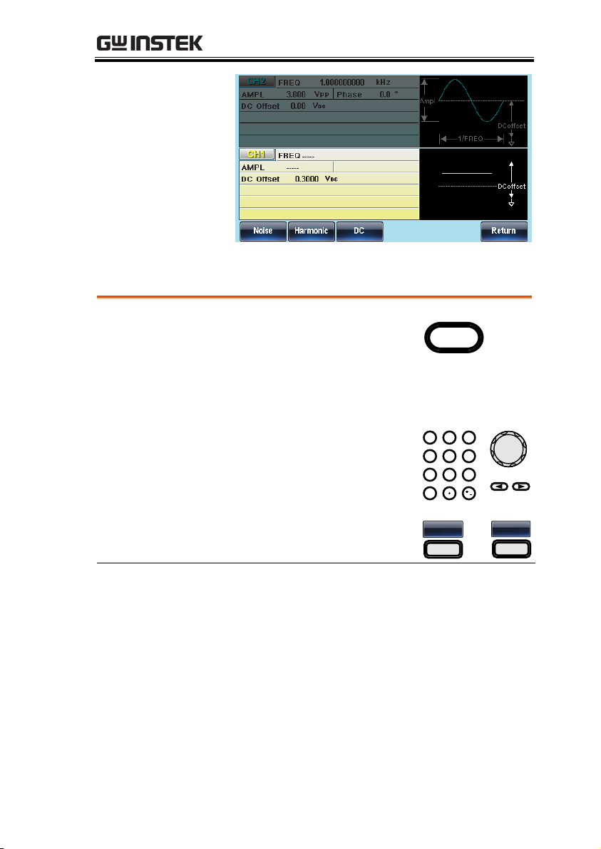
OPERATION
Panel Operation
1. Press the FREQ/Rate key.
FREQ/Rate
2. The FREQ parameter will become highlighted
in the parameter window.
3. Use the selector keys and
scroll wheel or number pad
to enter the frequency.
0
/
321
4
7 859
6
4. Choose a frequency unit by
pressing F2~F6.
uHz
F 2
~
MHz
F 6
Range
Sine
1μHz~30MHz
(20MHz AFG-3021/3022)
Square
1μHz~30MHz
(20MHz AFG-3021/3022)
Triangle
1μHz~1MHz
Pulse
1μHz~25MHz
(20MHz AFG-3021/3022)
Ramp
1μHz~1MHz
Setting the Waveform Frequency
85
Page 86
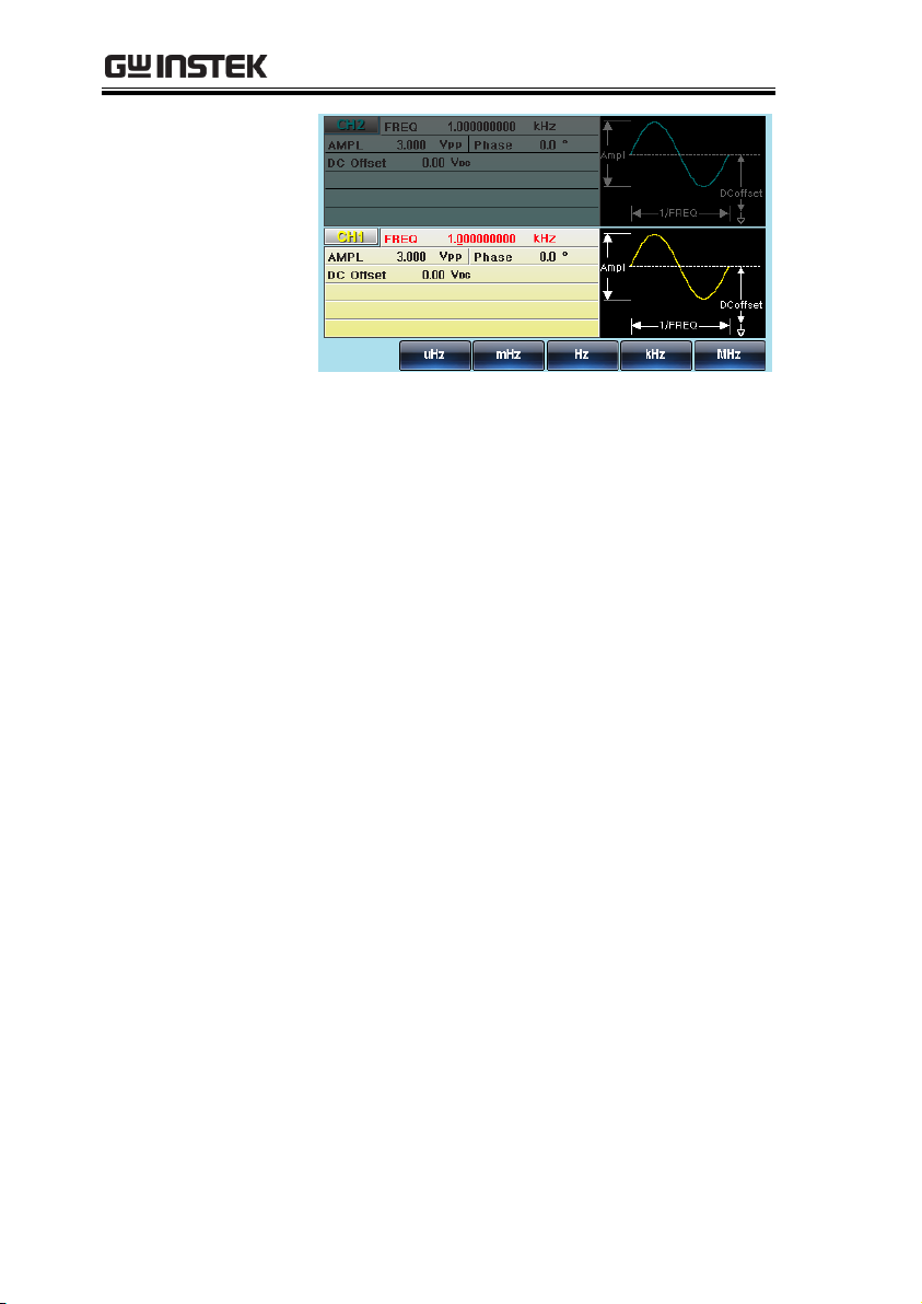
AFG-3021/3022/3031/3032 User Manual
86
Page 87
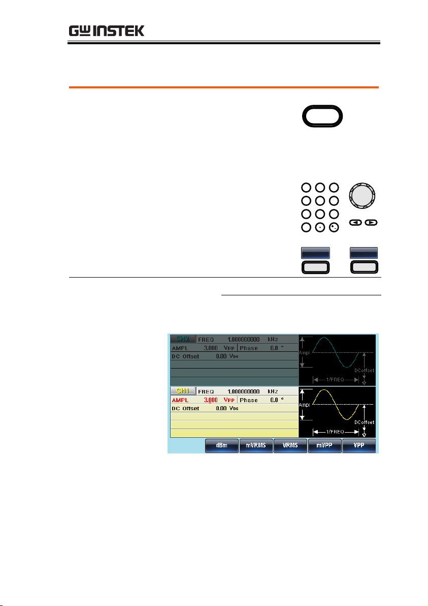
OPERATION
Panel Operation
1. Press the AMPL key.
AMPL
2. The AMPL parameter will become highlighted
in the parameter window.
3. Use the selector keys and
scroll wheel or number pad
to enter the amplitude.
0
/
321
4
7 859
6
4. Choose a unit type by
pressing F2~F6.
dBm
F 2
~
VPP
F 6
Range
50Ω load
High Z
Range
1mVpp~10Vpp
2mVpp~20Vpp
Unit
Vpp, Vrms, dBm
Setting the Amplitude
87
Page 88
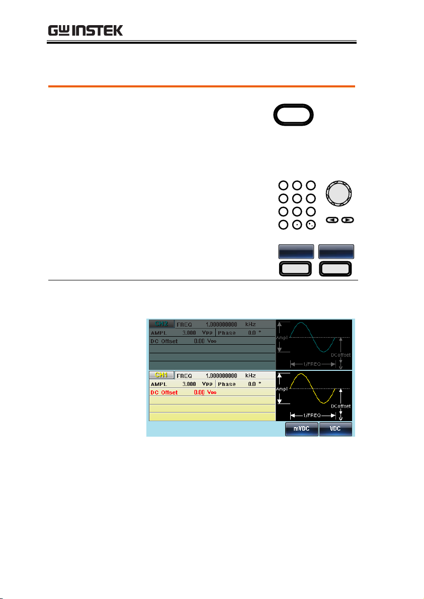
AFG-3021/3022/3031/3032 User Manual
Panel Operation
1. Press the DC Offset key.
DC Offset
2. The DC Offset parameter will become
highlighted in the parameter window.
3. Use the selector keys and
scroll wheel or number pad
to enter the DC Offset.
0
/
321
4
7 859
6
4. Press F5 (mVDC) or F6 (VDC)
to choose a voltage range.
mVDC
F 5
VDC
F 6
50Ω load
High Z
Range
±5Vdc
±10Vdc
Setting the DC Offset
88
Page 89

MODULATION
Amplitude Modulation (AM) ............................................. 91
Selecting AM Modulation .................................................... 92
AM Carrier Shape ................................................................. 92
Carrier Frequency ................................................................. 93
Modulating Wave Shape ...................................................... 94
AM Frequency ...................................................................... 95
Modulation Depth ................................................................ 96
Selecting (AM) Modulation Source ..................................... 98
Frequency Modulation (FM) ............................................ 100
Selecting Frequency Modulation (FM) .............................. 101
FM Carrier Shape ............................................................... 101
FM Carrier Frequency ......................................................... 102
FM Wave Shape.................................................................. 103
Modulation Frequency ....................................................... 104
Frequency Deviation ........................................................... 105
Selecting (FM) Modulation Source ................................... 106
Frequency Shift Keying (FSK) Modulation ........................ 108
Selecting FSK Modulation .................................................. 109
FSK Carrier Shape .............................................................. 109
FSK Carrier Frequency ........................................................ 110
FSK Hop Frequency ............................................................ 111
FSK Rate ............................................................................. 112
FSK Source ......................................................................... 113
Phase Modulation (PM) .................................................. 115
Selecting Phase Modulation (PM) ..................................... 116
PM Carrier Shape ............................................................... 116
PM Carrier Frequency......................................................... 117
MODULATION
The AFG-3021, AFG-3022, AFG-3031 & AFG-3032 Arbitrary
Function Generators are able to produce AM, FM, FSK and PWM
modulated waveforms as well as swept waveforms (frequency,
amplitude) and burst waveforms. Depending on the type of
waveform produced, different modulation parameters can be set.
Two different modulation modes can be active at the same time for
the AFG-3022 & AFG-3032.
89
Page 90

AFG-3021/3022/3031/3032 User Manual
PM Wave Shape ................................................................. 118
Modulation Frequency ....................................................... 119
Phase Modulation Deviation ............................................. 120
SUM Modulation ............................................................. 121
Selecting SUM Modulation ............................................... 122
SUM Carrier Shape ............................................................ 122
SUM Carrier Frequency ...................................................... 123
SUM Modulating Wave Shape .......................................... 123
SUM Frequency .................................................................. 124
SUM Amplitude ................................................................. 125
SUM Source ....................................................................... 126
Pulse Width Modulation .................................................. 128
Selecting Pulse Width Modulation .................................... 129
PWM Carrier Shape............................................................ 129
PWM Carrier Frequency ..................................................... 130
PWM Modulating Wave Shape .......................................... 130
Modulating Waveform Frequency ..................................... 131
Modulation Duty Cycle ...................................................... 132
PWM Source ...................................................................... 133
Sweep .............................................................................. 135
Selecting Sweep Mode ....................................................... 136
Sweep Type ........................................................................ 136
Setting Start and Stop Frequency/Amplitude ................... 137
Center Frequency and Span ............................................... 138
Sweep Mode ....................................................................... 140
Sweep Function .................................................................. 140
Sweep Waveform Type ....................................................... 141
Sweep Time ........................................................................ 142
Sweep Trigger Source ........................................................ 144
Burst Mode ..................................................................... 146
Selecting Burst Mode ......................................................... 146
Burst Modes ....................................................................... 146
Burst Frequency ................................................................. 147
Burst Cycle/Burst Count .................................................... 148
Infinite Burst Count ........................................................... 150
Burst Period ....................................................................... 150
Burst Phase ........................................................................ 152
Burst Trigger Source .......................................................... 153
Burst Delay ......................................................................... 155
Gated Trigger Polarity ........................................................ 156
Gated Trigger Phase .......................................................... 156
90
Page 91
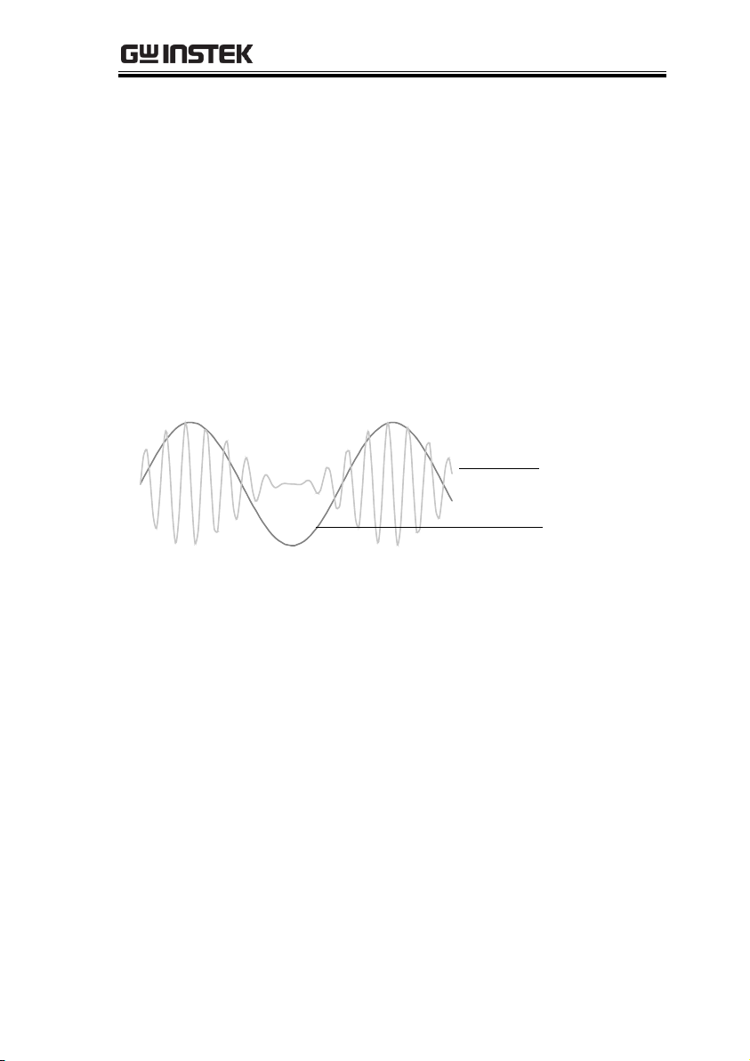
MODULATION
Modulated Carrier
Waveform
Modulating
waveform
Amplitude Modulation (AM)
An AM waveform is produced from a carrier waveform and a
modulating waveform. The amplitude of the modulated carrier
waveform depends on the amplitude of the modulating waveform.
The AFG-30XX function generator can set the carrier frequency,
amplitude and offset as well as internal or external modulation
sources. When using the function generator, only one type of
modulated waveform can be created at any one time for the selected
channel.
91
Page 92
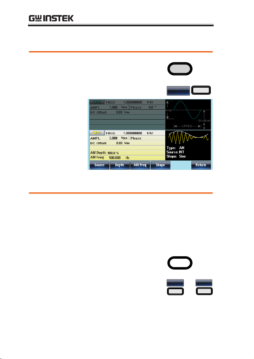
AFG-3021/3022/3031/3032 User Manual
Panel Operation
1. Press the MOD key.
MOD
2. Press F1 (AM).
AM
F 1
Background
Sine, square, triangle, ramp, pulse, noise or
arbitrary waveforms can be used as the carrier
shape. The default waveform shape is set to sine.
Harmonic and DC are not available as a carrier
shape. Before the carrier shape can be selected,
choose AM modulation mode, see page 36 or 94.
Select a Standard
Carrier Shape
1. Press the Waveform key.
Waveform
2. Press F1~F5 to choose the
carrier wave shape.
Sine
F 1
~
Ramp
F 5
Selecting AM Modulation
AM Carrier Shape
92
Page 93
MODULATION
Select an
Arbitrary
Waveform Carrier
Shape.
3. See the Arbitrary waveform
quick guide or chapter to use
an arbitrary waveform.
Page 44
Page 174
Range
AM Carrier Shape
sine, square, triangle, pulse,
ramp, arbitrary waveform
Panel Operation
1. With a carrier waveform,
press the FREQ/Rate key.
FREQ/Rate
2. The FREQ parameter will become highlighted
in the parameter window.
3. Use the selector keys and
scroll wheel or number pad
to enter the carrier frequency.
0
/
321
4
7 859
6
4. Press F2~F6 to select the
frequency range.
uHz
F 2
~
MHz
F 6
Range
Carrier Shape
Carrier Frequency
Sine
1μHz~30MHz
(20MHz AFG-3021/3022)
Square
1μHz~30MHz
(20MHz AFG-3021/3022)
Triangle
1μHz~1MHz
Pulse
1μHz~25MHz
(20MHz AFG-3021/3022)
Ramp
1μHz~1MHz
Carrier Frequency
The maximum carrier frequency depends on the carrier shape
selected. The default carrier frequency for all carrier shapes is 1kHz.
Continued next page
93
Page 94
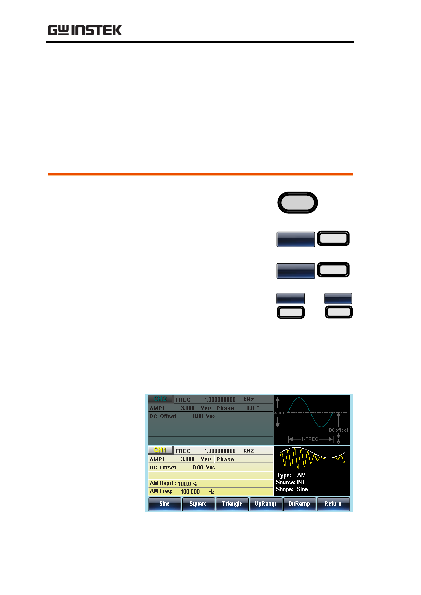
AFG-3021/3022/3031/3032 User Manual
Noise
N/A
ARB
125MHz to 1µHz
Panel Operation
1. Select MOD.
MOD
2. Press F1 (AM).
AM
F 1
3. Press F4 (Shape).
Shape
F 4
4. Press F1~F5 to select the
waveform shape.
Sine
F 1
~
DnRamp
F 5
Note
Square wave
50% Duty cycle
UpRamp
100% Symmetry
Triangle
50% Symmetry
DnRamp
0% Symmetry
Modulating Wave Shape
The function generator can accept internal as well as external
sources. The AFG-30XX has sine, square, triangle, up ramp and
down ramp modulating waveform shapes. Sine waves are the
default wave shape.
94
Page 95
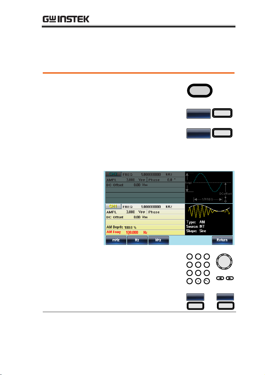
MODULATION
Panel Operation
1. Press the MOD key.
MOD
2. Press F1 (AM).
AM
F 1
3. Press F3 (AM Freq).
AM Freq
F 3
4. The AM Freq parameter will become
highlighted in the Waveform display area.
5. Use the selector keys and
scroll wheel or number pad
to enter the AM frequency.
0
/
321
4
7 859
6
6. Press F1~F3 to select the
frequency range.
mHz
F 1
~
kHz
F 3
Range
Modulation frequency
2mHz~20kHz
Default frequency
100Hz
AM Frequency
The frequency of the modulation waveform (AM Frequency) can be
set from 2mHz to 20kHz.
95
Page 96
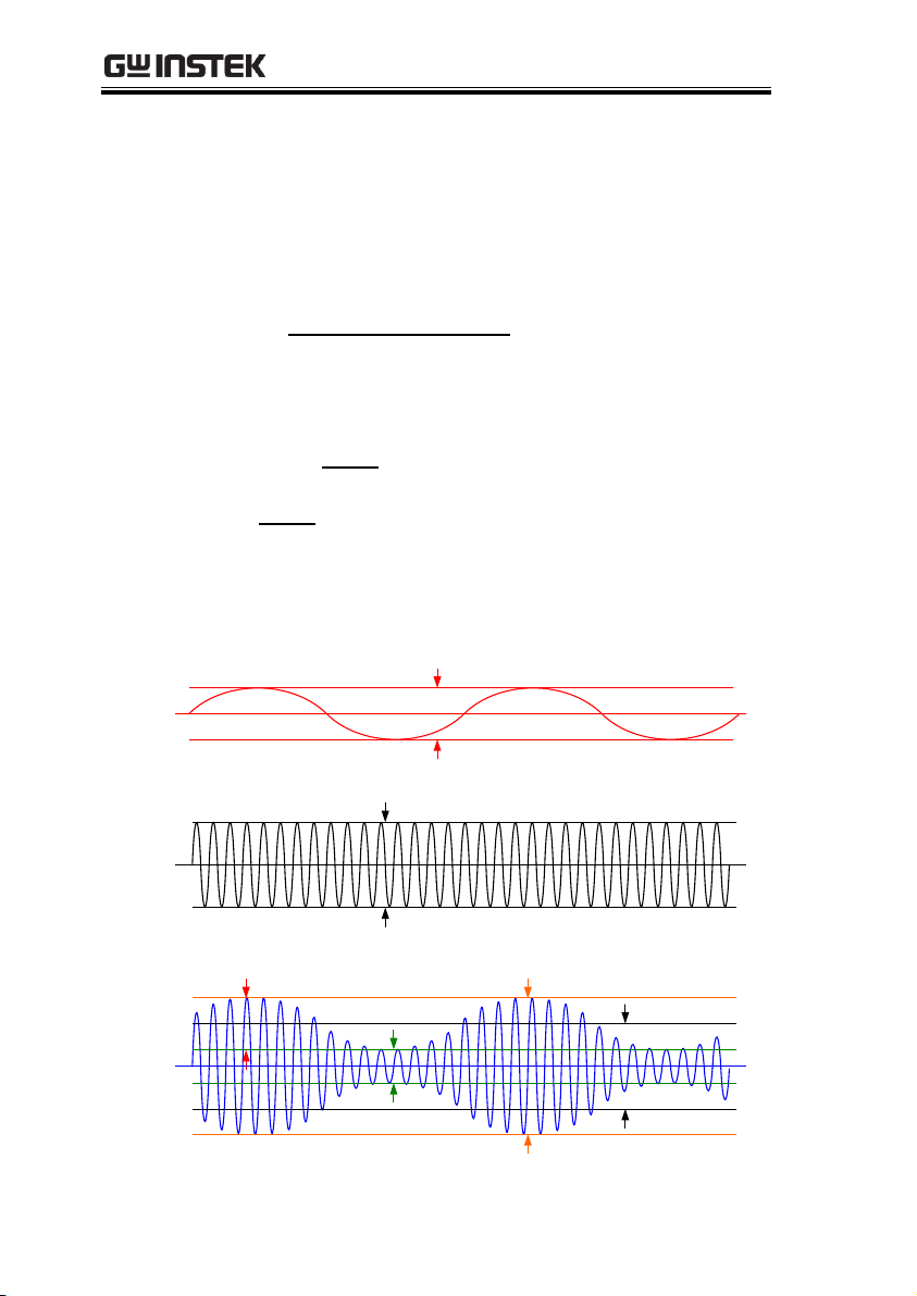
AFG-3021/3022/3031/3032 User Manual
100x
veVoltageCarrrierWa
eWaveVoltagModulating
DepthModulation
)
100
1(max
Depth
VcV Vpp
)
100
1(min
Depth
VcV
Modulation
Signal
Carrier
Signal
Vc = Carrier Amplitude
Vc
Vmax = Vpp
Vmin
Output
Signal
Vm = Modulation Amplitude
Vm
Modulation Depth
The modulation depth determines the maximum and minimum
amplitude of the AM waveform. The modulation depth (as a
percentage) is defined by the ratio of the modulating waveform
voltage and the carrier waveform voltage multiplied by 100:
The maximum and minimum peak to peak voltage of the modulated
waveform can then be defined by:
Below is a visual explanation of the relationship between the
modulation signal, carrier signal and the resulting output signal.
Note: Vpp is the amplitude setting on the AFG.
96
Page 97
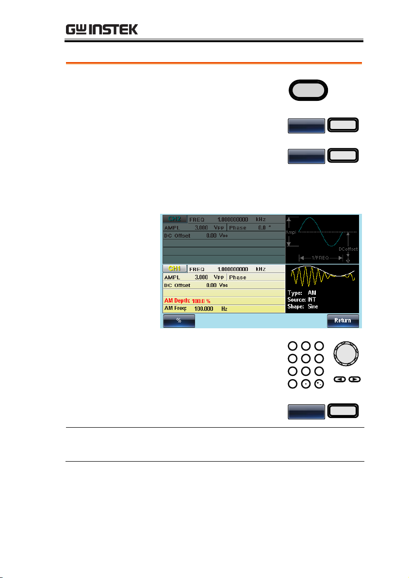
MODULATION
Panel Operation
1. Press the MOD key.
MOD
2. Press F1 (AM).
AM
F 1
3. Press F2 (Depth).
Depth
F 2
4. The AM Depth parameter will become
highlighted in the waveform display area.
5. Use the selector keys and
scroll wheel or number pad
to enter the AM depth.
0
/
321
4
7 859
6
6. Press F1 (%) to choose %
units.
%
F 1
Range
Depth
0%~120%
Default depth
100%
97
Page 98
AFG-3021/3022/3031/3032 User Manual
Note
When the modulation depth is greater than 100%, the
output cannot exceed ±5VPeak (10kΩ load).
If an external modulation source is selected,
modulation depth is limited to ± 5V from the MOD
INPUT terminal on the rear panel. For example, if
modulation depth is set to 100%, then the maximum
amplitude is +5V, and the minimum amplitude is -5V.
Panel Operation
1. Press the MOD key.
MOD
2. Press F1 (AM).
AM
F 1
3. Press F1 (Source).
Source
F 1
4. To select the source, press F1
(Internal) or F2 (External).
INT
F 1
~
EXT
F 2
External Source
Use the MOD INPUT terminal
on the rear panel when using an
external source.
42V
MAX
MOD
For AFG-3022/3032, using the CH1 or CH2 MOD
input depends on which channel is used for
modulation.
Note
If an external modulation source is selected,
modulation depth is limited to ± 5V from the MOD
INPUT terminal on the rear panel. For example, if
modulation depth is set to 100%, then the maximum
amplitude is +5V, and the minimum amplitude is -5V.
Selecting (AM) Modulation Source
The function generator will accept an internal or external source for
AM modulation. The default source is internal.
98
Page 99
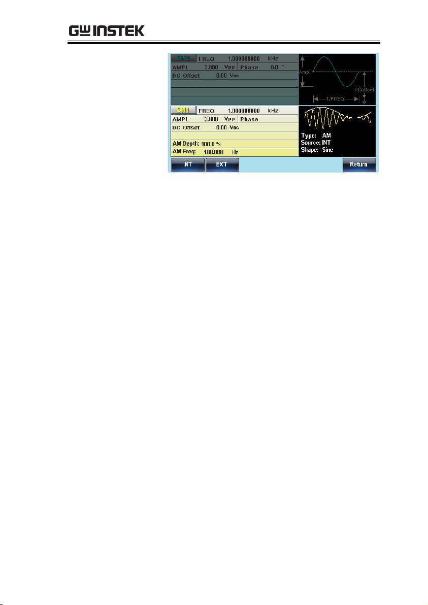
MODULATION
99
Page 100
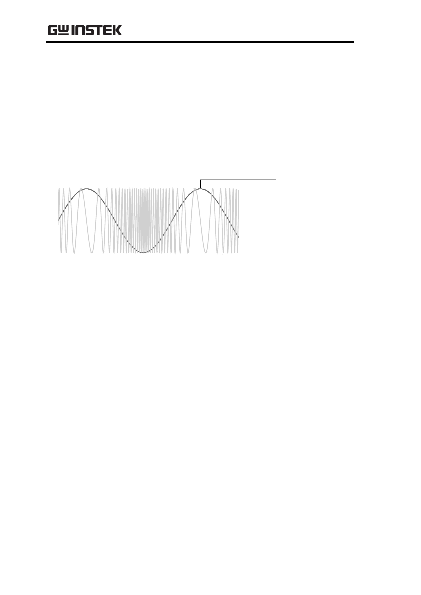
AFG-3021/3022/3031/3032 User Manual
Modulated Carrier
Waveform
Modulating
waveform
Frequency Modulation (FM)
An FM waveform is produced from a carrier waveform and a
modulating waveform. The instantaneous frequency of the carrier
waveform varies with the magnitude of the modulating waveform.
When using the function generator, only one type of modulated
waveform can be created at any one time for the selected channel.
100
 Loading...