

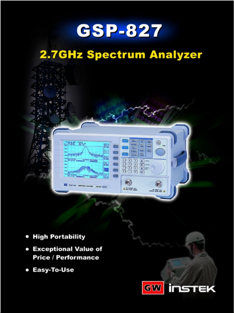

GSP-827 Spectrum Analyzer
Portable and Easy-To-Use Spectrum Analyzer with
Exceptional Price/Performance
GSP-827 covering 9kHz ~ 2.7GHz frequency range, is designed to meet the demands of production or development
tests of RF products, and maintenance or installation of on-site wireless communication systems. The exceptional price/
performance, high portability, and easy-to-use design make GSP-827 a very accurate and handy instrument for most of the
RF measurement applications.
High Portability and Large Memory Size :
With AC/DC/Battery power operation, 4.5kg light weight, compact size, and 9kHz ~ 2.7GHz frequency coverage, GSP-827
is a very convenient tool for the field service of RF systems. The 100 sets of memory of GSP-827 to save 100 trace/set-up
make repetitive measurements with mass storage of test results possible. The large memory size of GSP-827 is also a
useful feature for the characteristic verification of products and components. The repetitive measurement results could be
saved in GSP-827, and then transferred to the PC for further analysis.
Exceptional Price/Performance :
Utilizing advanced synthesizer-based design, GSP-827 delivers accurate and reliable measurements. The remarkable
performance of -100dBm average noise floor and -100dBm ~ 20dBm wide input range, greatly extends the application range
of the product. The ACPR, OCBW and CH power measurements make the verification of wireless communication
characteristics simple and easy. The split window display to simultaneously show the spectrum in two separate frequency
spans and set-ups makes the complicated measurements a lot easier. The optional built-in tracking generator with normalized
output gives a useful mean for the performance test of RF components and modules. All the GSP-827 innovative features
reflect to the price/performance value of the users.
Features
Frequency Range : 9kHz ~ 2.7GHz
Input Range : -100dBm ~ +20dBm
Average Noise Floor : -100dBm
Power Measurements : ACPR/OCBW/CH Power
Split Window: Simultaneous Measurements in Two
Separate Frequency Spans
10 Markers : Delta Mode, Peak Search, Peak Track
Trace Function : Dual-Trace Display, Peak Hold, Freeze, Average,
Trace Math
Limit Line : Upper/Lower Limit with Pass/Fail Test
Trigger Function : Video/ External
Clock/Calendar : Time/Date Stamp in Saved Data
Wide Range of External Reference Clock : 1MHz~19.2MHz
100 Trace/State Memories with Date/Time Stamp and File Name
TG : 9kHz ~ 2.7GHz, -50dBm ~ 0dBm (Option)
AC/DC/Battery Operation (Option)
Light Weight at 4.5kgCompact Size and
1 2 3 4
9 10 118 12
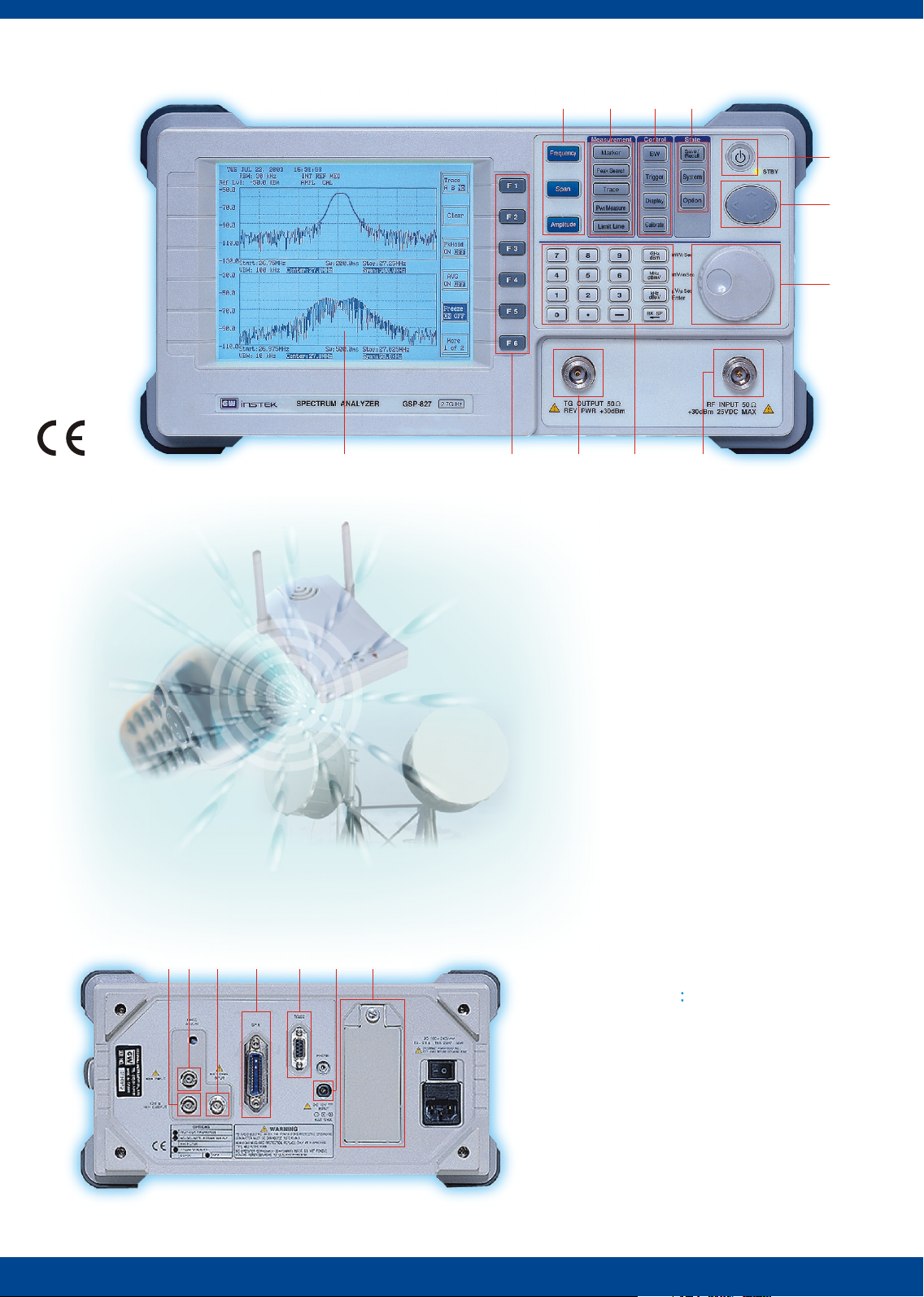
Panel Introduction :
1. Main functions
2. Measurement keys
3. Control keys
4. State keys
5. Power Button
6. Arrow key
7. Fly Wheel
8. 640 x 480 High Resolution LCD Display
9. Function keys
10. TG Output
11. Numeric Keypad
12. RF Input
5
6
7
1
234567
Rear Panel
1. Battery Pack Slot (Opt.)
2. DC Power Supply (Opt.)
3. RS-232C
4. GPIB (Opt.)
5. External Trigger
6. 10 MHz REF Output
7. REF input

CH Power/OCBW/ACPR
OCBW MeasurementChannel Power Measurement
GSP-827 provides versatile power measurement capabilities including Channel Power(CHP),
Occupied Bandwidth(OCBW) and Adjacent Channel Power Ratio(ACPR), which are essential
to the transmission characteristics verification of wireless communication systems.
CH Power :
With the setting of channel center frequency and channel bandwidth , GSP-827 automatically
measures the total transmitted power within the set bandwidth of the designated channel.
OCBW :
With the setting of channel center frequency and the percentage of total transmitted power,
GSP-827 automatically indicates the bandwidth that represents the set percentage of total
transmitted power.
ACPR :
ACPR measurement function allows the user to check the interference or leakage power
between the designated channel and its adjacent channels. Due to the sophistication of the
modern communication system, GSP-827 has the capabilities to measure the power ratio
between the designated channel and its adjacent channels either within the same
communication system or that of a different communication system.
Adjiacent Channel Power Ratio
10 Markers(Peak Track, Peak Search)
Multi-Markers Mode Delta Marker Mode
GSP-827 gives the high operation flexibility under both Delta-Marker mode and MultiMarker mode. Up to 10 markers could be selected to show their absolute values of
frequency and level in a table on the screen. The relative values of frequency and level of
selected markers-to-reference marker could be shown under an easy operation process.
All Markers , each with full marker capabilities including Peak Search, Marker to Center ,
and Peak Track, provide fast and comprehensive interpretations of measurements.

100 Trace/State Memories
100 Sets of Trace/State Memories
GSP-827 provides up to 100 sets of memory to Save and Recall the Waveform and the
Set-Up of measurements. The specified file name and the Date/Time stamp could be
attached to each saved file for easy recognition and analysis of all the saved information.
With large memory size, GSP-827 greatly facilitates the measurements of on site service
and the product characteristic verification.
Limit Line
Limit Line for Pass/Fail Testing
The Upper Limit Line and Lower Limit Line could be easily set to monitor the abnormal
signals under user's definition. Each Limit Line could be set by linking the points, which
are positioned by entering the values of both frequency and level referring to the
frequency axis and the level axis.
Split Window
Split Window To Observe Two Different Signals
Split Window allows user to view the frequency spectrum of an input signal on two
separate screen areas under two different settings of GSP-827 . This useful feature of
two-measurements-in-one usually means the value of two-instruments-in-one.

Tracking Generator
Tracking Generator To Observe Characteristic of Filter
With optional Tracking Generator, GSP-827 becomes a handy tool to do the characteristic
verification of dual-port components such as filters and amplifiers etc. The normalization
process of output signal compensates the uneven signal loss caused by the effect of
measurement cables and connectors, and therefore ensures an accurate measurement.
AC/DC/Battery Power Operation
AC/DC Battery Pack
In the field service environment or the places without AC power , GSP-827 with optional
AC/DC/Battery operation gives the convenience to use a lab instrument without AC power,
and maintains the lab measurement accuracy at the same time. A soft carrying case and
the DC power cable with car lighter plug for GSP-827 are also available to facilitate the
outdoor applications.

PC Software
Carrying Case
Free Charge of PC Software Carrying Case with GSP-827 and Accessories
GSP-827 offers a PC software free of charge that
customers can easily send the acquired trace and
the associated parameters from GSP-827 to PC
through RS-232C.
Application
Maintenance
Radio/TV Broadcasting System
Industrial Wireless Automation
Installation/Maintenance
Cellular/Base Station
WLAN Hot-Spot
Wireless Communication System
EMC Pre/Post
Compliance Test
CATV
HDVT
With the carrying case , GSP-827 makes the on-site RF measurements
more convenient. The carrying case not only provides the protection and
portability of GSP-827 but also carries the test accessories , such as RF
cable, antenna, and battery to facilitate the measurements.
Education
RF and Wireless
Communication Lab
RF Components
Amplifier LNB
Filter RFID
Oscillator.. Antenna
GSP-827
Production Testing of
Wireless Products
WLAN/ Blue Tooth Module
Cordless Phone
Wireless Keyboard, Mouth..
Instrument Test Lead Option
ADP-001
Adaptor
BNC(J/F) ~ N(P/M)
ADP-002
Adaptor
SMA(J/F) ~ N (P/M)
ADP-101
BNC(J/F) 75 ~
BNC(P/M) 50
ATN-100
10dB Attenuaror
N(J) ~ N(P)
General Kit set
ADP-002 x 2
ATN-100 x 1
GTL-303 x 2
GSC-002 x 1
Opt.08
GRA-404 Rack Adapter Panel
Rack Mounting (19", 4U)
GAK-001
Termination 50
N (P)
GAK-002
Cap with Chain
N (P)
ATA-001
BNC Antenna
GTL-301
RF Cable (RG 223
N(P) , 1000mm)
CATV Kit set
ADP-001 x 2
ADP-101 x 2
GTL-304 x 2
GSC-003 x 1
Opt.09
GTL-302
RF Cable Assembly
(RG223, N(P),
300mm)
GTL-303
RF Cable Assembly
(SMA(P), RD316,
600mm)
GTL-304
RF Cable Assembly
(RG223, N(P) ~ N(J),
300mm)
GTL-401
DC Power Cord
with DC Jack and
Lighter Plug,
Current 5A Opt.11
RLB Kit set
GAK-001 x 1
GAK-002 x 1
GTL-302 x 2
GSC-004 x 1
Opt.10
GSC-001 Soft Carrying Case
Opt.07

Specifications
FREQUENCY
RESOLUTION
BANDWIDTH
AMPLITUDE
DYNAMIC RANGE
DISPLAY SYSTEM
FUNCTIONS
CONNECTORS
POWER SOURCE
ACCESSORIES
DIMENSIONS & WEIGHT
Frequency Range
Aging Rate
Span Range
Phase Noise
Sweep Time Range
RBW Range
RBW Accuracy
Video Bandwidth Range
Measurement Range
Overload Protection
Reference Level Range
Amplitude Display Range
Amplitude Accuracy
Frequency Flatness
Amplitude Level Linearity
Average Noise Floor
Third Inter-Modulation
Harmonic Distortion
Non-Harmonic Spurious
Display Device
Display Function
Marker Mode
Internal Memory
Peak Search
Trace Number
Power Measurement
Trigger
Limit Line
Calibrate Signal
Interface
RF Input
External Reference
Clock Input
Reference Clock Output
DC Input
RS-232C
9kHz~2.7GHz
10ppm, 0~50 C, 5ppm/yr
2kHz~ 2.5GHz in 1-2-5 sequence, full span, zero span
-85dBc/Hz @1GHz 20kHz offset typical
50ms~25.6s
3kHz, 30kHz, 300kHz, 4MHz
15%
10Hz~1MHz in 1-3 steps
-100dBm~+20dBm : 1MHz~2.5GHz @3k RBW ; -95dBm~+20dBm : 2.5GHz~2.7GHz @3k RBW
-75dBm~+20dBm : 150kHz~1MHz @3k RBW; -65dBm~+20dBm : 50kHz~150kHz @3k RBW
+30dBm, 25VDC
-30dBm~+20dBm
75dB
1.5dB @100MHz
1.5dB
1.5dB over 70dB
-100dBm: 1MHz~2.5GHz;
<-70dBc @-40dBm Input, 2MHz apart
-95dBm: 2.5GHz~2.7GHz;
<-60dBc @-40dBm Input
<-60dBc @typical down from Reference Level 150k~2.7GHz
640 x 480 high resolution graphical LCD, B&W
Contrast, backlight ON/OFF, Invert screen;
Normal and delta mode;
100 traces and setup for Save/Recall
To peak, to center , next peak, peak right,
Number:2,tr A and B for display memory;Functions:peak hold,average,freeze,math;Detect:sample,peak+,AVG 1/2/3,quasi-peak
ACPR x 2, OCBW, Channel Power
Number: Up to 10 in multi marker mode
Functions:Video,External;Mode:continuous,single;Source:video,external(0~5V rising edge);Setting:Trigger delay,Trigger frequency
Number: 2, high and low;
Functions: Edit:Insert, Delect, Undo Pass/Fail
100MHz, -30dBm
RS-232C standard
Type : N female, 50 nominal ;
Type: BNC female
RF input VSWR : <1.5:1, @0dBm Reference Level
1M, 1.544M, 2.048M, 5M, 10M, 10.24M, 13M, 15.36M, 15.4M, 19.2M
Type:BNC female, 10MHz
Jack:5.5mm, 12V
Sub-D 9 pins female
AC 100 ~ 240V, 48 ~ 63Hz
Instruction manual x 1, Power cord x 1
330(W) x 170(H) x 340(D) mm, Approx. 4.5kg
ORDERING INFORMATION - OPTION
Opt. 01
Opt. 02
Opt. 03
Opt. 06
Opt. 07
Opt. 08
Opt. 09
Opt. 10
Opt. 11
Opt. 12
Opt. 13
Opt. 14
Opt. 15
Opt. 16
Note : 1. Only one option could be selected among option 12 to 16 for any given GSP-827 unit. (*)
2. It is necessary to be installed by factory (ordering: Opt. 01, 02, 03, 06, 12, 13, 14, 15, 16)
Tracking Generator
AC/DC/Battery Operation with Battery pack
1ppm Stability
GPIB Interface
Soft Carrying Case
General Kit set
CATV Kit set
RLB Kit set
DC Power Line
EMI Filters
Demodulator
EMI filters and 300Hz RBW
EMI filters and Demodulator
EMI filters, 300Hz RBW and Demodulator
(*)
(*)
(*)
(*)
Frequency Range
Amplitude Range
Amplitude Accuracy
Amplitude Flatness
Harmonics
Reverse Power
Impedance
RF Output VSWR
AC 100V ~ 240V , DC 12V and 10.8V Li-Ion battery pack x 2)
1ppm , 0 ~ 50 C, 1ppm/yr
IEEE 488 bus
GSC-001
ADP-002: adaptor, SMA(J/F) ~ N(P/M) x 2
ATN-100: 10dB attenuator, N(J) ~ N(P) x 1
GTL-303: RF cable assembly(SMA(P),RD316,600mm)x2
GSC-002: Kit box x 1
ADP-001: adaptor, BNC(J/F) ~ N(P/M) x 2
ADP-101: adaptor,BNC(J/F)75 ~BNC(P/M)50 x 2
GTL-304: RF cable assembly(RG223,N(P)-N(J),300mm)x2
GSC-003: Kit box x 1
GAK-001: termination 50 , N(P) x 1
GAK-002: Cap with chain, N(P) x 1
GTL-302: RF cable assembly(RG223,N(P),300mm)x2
GSC-004: Kit box x 1
GTL-401: DC power cord with DC Jack and lighter plug, Current 5A
RBW Selections: 9kHz and 120kHz, 6dB bandwidth; RBW Accuracy: 15%
Demodulation: AM, FM ;
RBW Selections: 9kHz and 120kHz,6dB bandwidth 300Hz,3dB bandwidth;
RBW Selections: 9kHz and 120kHz, 6dB bandwidth
RBW Accuracy: 15%
Demodulation: AM, FM
Output: Internal speaker, 3.5mm stereo jack wired for mono operation
(*)
RBW Selections: 9kHz and 120kHz, 6dB bandwidth 300Hz, 3dB bandwidth
RBW Accuracy: 15%
Demodulation: AM, FM
Output: Internal speaker, 3.5mm stereo jack wired for mono operation
-75dBm: 150kHz~1MHz;
-65dBm: 50kHz~150kHz
split window: upper and lower
peak left and peak track
9kHz ~ 2.7GHz
-50dBm ~ 0dBm
1dB@100MHz, 0dBm
1.5dB@0dBm
<-30dBc typical
+30dBm
Type: N female, 50 nominal
< 1.5 : 1
Output: Internal speaker, 3.5mm stereo jack wired for mono operation
RBW Accuracy: 15%
Specifications subject to change without notice.
GOOD WILL INSTRUMENT CO., LTD.
No. 95-11, Pao-Chung Road, Hsin-Tien City,
Taipei Hsien, Taiwan, R.O.C.
TEL: 886-2-29179188 FAX: 886-2-29179189
http://www.goodwill.com.tw
E-mail: marketing@goodwill.com.tw
U.S.A.
INSTEK CORP.
3661 Walnut Avenue
Chino, CA 91710, U.S.A.
Tel : +1-909-5918358
Fax : +1-909-5912280
http://www.instek.com
MALAYSIA
GOOD WILL Southeast Asia Sdn. Bhd.
Plot 522, Lorong Perusahaan Baru 3,
Prai Industrial Estate, 13600 Perai,
Penang, Malaysia.
Tel : +60-4-3981988
Fax : +60-4-3981989
CHINA
GOOD WILL Instrument(Shanghai)Co.,Ltd.
8F, of NO.2 Building, No.889 Yishan Road,
Shanghai, China.
TEL: +86-21-64853399
FAX: +86-21-54500789
SP-8270GD2BH
 Loading...