


Electrical Safety Analyzer
GPT-10000 Series
USER MANUAL
ISO-9001 CERTIFIED MANUFACTURER

This manual contains proprietary information, which is protected by
copyright. All rights are reserved. No part of this manual may be
photocopied, reproduced or translated to another language without
prior written consent of Good Will company.
The information in this manual was correct at the time of printing.
However, Good Will continues to improve products and reserves the
rights to change specification, equipment, and maintenance
procedures at any time without notice.
Good Will Instrument Co., Ltd.
No. 7-1, Jhongsing Rd., Tucheng Dist., New Taipei City 236, Taiwan.

Table of Contents
Table of Contents
SAFETY INSTRUCTIONS .................................................. 5
GETTING STARTED .......................................................... 9
GPT-10000 Series Overview ................. 10
Front Panel Overview ........................... 15
Rear Panel Overview ............................ 19
Set Up .................................................. 22
OPERATION .................................................................. 29
Menu Tree ............................................ 31
Test Lead Connection ........................... 36
Manual Tests ....................................... 39
Special MANU Test Mode (000) ........... 90
Sweep Function.................................... 92
Automatic Tests ................................... 95
System Settings ................................. 119
EXTERNAL CONTROL ................................................... 165
External Control Overview .................. 166
REMOTE CONTROL ...................................................... 172
Interface Configuration ...................... 173
Command Syntax ............................... 178
Command List ................................... 181
Error Messages .................................. 238
FAQ .............................................................................. 239
APPENDIX .................................................................... 242
Fuse Replacement .............................. 242
Tester Errors ...................................... 243
3

GPT-10000 Series User Manual
Factory Default Parameters ................ 246
GPT-10000 Specifications .................. 248
GPT-15001/15002/15003 Dimensions 256
GPT-15004 Dimensions ...................... 257
GPT-12001/12002/12003 Dimensions 258
GPT-12004 Dimensions ...................... 259
Declaration of Conformity .................. 260
Declaration of Conformity .................. 261
INDEX .......................................................................... 262
4

SAFETY INSTRUCTIONS
WARNING
Warning: Identifies conditions or practices that
could result in injury or loss of life.
CAUTION
Caution: Identifies conditions or practices that
could result in damage to the instrument or to
other properties.
DANGER High Voltage
Attention Refer to the Manual
Protective Conductor Terminal
Frame or Chassis Terminal
Earth (ground) Terminal
SAFETY INSTRUCTIONS
This chapter contains important safety
instructions that you must follow during
operation and storage. Read the following before
any operation to ensure your safety and to keep
the instrument in the best possible condition.
Safety Symbols
These safety symbols may appear in this manual or on the
instrument.
5

GPT-10000 Series User Manual
Do not dispose electronic equipment as unsorted
municipal waste. Please use a separate collection
facility or contact the supplier from which this
instrument was purchased.
General
Guideline
CAUTION
Do not place any heavy object on the
instrument.
Avoid severe impact or rough handling that
leads to damaging the instrument.
Do not discharge static electricity to the
instrument.
Use only mating connectors, not bare wires, for
the terminals.
Do not block the cooling fan opening.
Do not disassemble the GPT-10000 unless you
are qualified.
Position
Guideline
WARNING
The rear position of the GPT-10000 should be
placed in an area with easy accessible for power
disconnection, that is, unplugging the power
cord with ease.
Keep away from the device under test which
connects with the GPT-10000 when test is
underway. In addition, while test is ongoing,
never touch the device under test, the GPT10000 as well as other relevant units.
Any inappropriate manner that is unspecified
by the manufacturer may result in irreversible
harms or impaired protection by the GPT-10000.
Safety Guidelines
6

SAFETY INSTRUCTIONS
(Measurement categories) EN 61010-1:2010 specifies the
measurement categories and their requirements as follows. The
GPT-10000 does not fall under category II, III or IV.
Measurement category IV is for measurement performed at the
source of low-voltage installation.
Measurement category III is for measurement performed in the
building installation.
Measurement category II is for measurement performed on the
circuits directly connected to the low voltage installation.
Power Supply
WARNING
AC Input voltage range:
AC 100V – 240V ± 10%
Frequency: 50Hz/60Hz
To avoid electrical shock connect the protective
grounding conductor of the AC power cord to
an earth ground.
Cleaning the
GPT-10000
Disconnect the power cord before cleaning.
Use a soft cloth dampened in a solution of mild
detergent and water. Do not spray any liquid.
Do not use chemicals containing harsh material
such as benzene, toluene, xylene, and acetone.
Operation
Environment
Location: Indoor, no direct sunlight, dust free,
almost non-conductive pollution (Note below)
Relative Humidity: ≤ 70% (no condensation)
Altitude: < 2000m
Temperature: 0˚C~40˚C
7

GPT-10000 Series User Manual
(Pollution Degree) EN 61010-1:2010 specifies the pollution degrees
and their requirements as follows. The GPT-10000 falls under
degree 2.
Pollution refers to “addition of foreign matter, solid, liquid, or
gaseous (ionized gases), that may produce a reduction of dielectric
strength or surface resistivity”.
Pollution degree 1: No pollution or only dry, non-conductive
pollution occurs. The pollution has no influence.
Pollution degree 2: Normally only non-conductive pollution
occurs. Occasionally, however, a temporary conductivity caused
by condensation must be expected.
Pollution degree 3: Conductive pollution occurs, or dry, non-
conductive pollution occurs which becomes conductive due to
condensation which is expected. In such conditions, equipment
is normally protected against exposure to direct sunlight,
precipitation, and full wind pressure, but neither temperature
nor humidity is controlled.
Storage
environment
Location: Indoor
Temperature: -10°C to 70°C
Relative Humidity: ≤ 85% (no condensation)
Disposal
Do not dispose this instrument as unsorted
municipal waste. Please use a separate collection
facility or contact the supplier from which this
instrument was purchased. Please make sure
discarded electrical waste is properly recycled to
reduce environmental impact.
8

GETTING STARTED
GPT-10000 Series Overview ............................................ 10
Series lineup ..............................................................................................10
Lineup Overview......................................................................................11
Main Features ...........................................................................................11
Accessories ................................................................................................12
Package Contents .....................................................................................14
Front Panel Overview ..................................................... 15
GPT-12001/12002/12003/12004/15001/15002/15003/15004 ...........15
Rear Panel Overview ...................................................... 19
GPT-12001/12002/12003/12004/15001/15002/15003/15004 ...........19
Set Up ........................................................................... 22
Tilting the Stand .......................................................................................22
Line Voltage Connection and Power Up ..............................................23
Installing the Optional GPIB Card .........................................................24
Workplace Precautions ............................................................................25
Operating Precautions .............................................................................26
Basic Safety Checks ..................................................................................28
GETTING STARTED
This chapter describes the safety analyzer in a
nutshell, including its main features and front /
rear panel introduction. After going through the
overview, please read the safety considerations in
the Set Up chapter.
9

GPT-10000 Series User Manual
GPT-10000 Series Overview
Series lineup
The GPT-10000 Series Safety Analyzers are AC/DC withstanding
voltage, insulation resistance, ground bond and continuity safety
analyzers.
By and large, GPT-10000 Series has 2 major categories, one is GPT12XXX models, and the other is GPT-15XXX models. The subordinate
models of 2 categories share the same test functions but with different
specifications. We use the term “X” for the 2nd digit of model names
described below to stand for both 2 categories in common.
The GPT-1X001 is AC withstanding voltage and continuity tester,
the GPT-1X002 is AC/DC withstanding voltage and continuity
tester and the GPT-1X003 is AC/DC withstanding voltage,
insulation resistance and continuity tester. The GPT-1X004 includes
all the test functions of the other models, plus the ground bond
testing. See the following Lineup Overview for more details.
The GPT-10000 Series can store up to 100 manual tests, as well as
run up to 10 manual tests sequentially as an automatic test,
allowing the safety analyzers to accommodate any number of
safety standards, including IEC, EN, UL, CSA, GB, JIS and others.
Note: Throughout this user manual, the terms ACW, DCW, IR, GB
and CONT refer to AC Withstanding, DC Withstanding, Insulation
Resistance, Ground Bond and Continuity testing, respectively.
10

GETTING STARTED
Model name
ACW
DCW
IR
GB
CONT
GPT-12001
GPT-12002
GPT-12003
GPT-12004
GPT-15001
*
GPT-15002
*
GPT-15003
*
GPT-15004
*
Short Current > 200mA
Performance
ACW: 0.05kV~5kVAC
DCW: 0.05kV~6kVDC
IR: 50V~1200V (50V steps)*
GB: 3A~32A
CONT: 100mA (fixed)
Lineup Overview
Main Features
11

GPT-10000 Series User Manual
Features
Ramp up time control
Ramp down time control
Safety discharge
100 test conditions (MANU mode)
100 automatic tests (AUTO mode)
Over temperature, voltage and current
protection
Pass, Fail, Test, High Voltage and Ready
indicators
PWM output (90% efficiency, increased
reliability)
Interlock (configurable)
Rear panel output
Interface
Remote control start/stop interface terminal
RS232/USB interface for programming
Optional GPIB interface for programming
Optional LAN interface for programming
Signal I/O port for pass/fail/test monitoring
and start/stop control/interlock
Standard
Accessories
Part number
Description
GHT-115x1
Test lead
Region dependent
Power cord
GTL-215x1
GB test lead
(GPT-12004/GPT-15004 only)
GHT-119
Remote terminal cable
N/A
Interlock key
Accessories
12

GETTING STARTED
Optional
Accessories
Part number
Description
GHT-205
High Voltage Test Probe
GHT-113
High Voltage Test Pistol
GTL-232
RS232C cable
GTL-248
GPIB cable
GTL-246
USB cable (A to B type)
GRA-440
Rack Adapter Panel (19”, 4U)
(GPT-12000/15000 only)
Options
Part number
Description
Opt.01 GPIB Interface
GPIB module
Opt.02 LAN Interface
LAN module
13

GPT-10000 Series User Manual
Opening the box
Contents
(single unit)
GPT-10000 unit
Quick Start Guide
User manual CD
CTC (Calibration
Traceable Certificate)
Power cord x1 (region
dependent)
GHT-115 test leads x1
GTL-215 GB test leads
x1 (GPT-12004/GPT15004 only)
GHT-119 Remote
terminal cable
Interlock key
Note
Keep the packaging, including the box, polystyrene
foam and plastic envelopes should the need arise
to return the unit to GW Instek.
Package Contents
Check the contents before using the GPT-10000 series.
14

GETTING STARTED
1
2
3
4 5
6
7
8
9
0
A
B
C
D
E
F
G
Item
Description
1
STOP Button
2
START Button
3
POWER Switch
4
Test Function Keys (Green Zone)
5
Display
6
Mode Keys (AUTO, MANUAL, SYSTEM in Red Zone)
7
Soft Keys (Blue Zone)
8
USB A-Type Host Port
9
PASS/FAIL Indicators
0
REMOTE Terminal
A
Scroll Wheel
B
HIGH VOLTAGE Indicator
C
HIGH VOLTAGE Output Terminal
D
SENSE L & RETURN Terminal
E
SENSE H & Output Terminal
F
SOURCE L (GPT-12004/GPT-15004 only)
G
SOURCE H (GPT-12004/GPT-15004 only)
Front Panel Overview
GPT-12001/12002/12003/12004/15001/15002/15003/15004
15

GPT-10000 Series User Manual
STOP button
The STOP button is used to
stop/cancel tests. The STOP button
will also put the safety analyzer in the
READY status to begin testing.
START button
The START button is used to start tests.
The START button can be used to start
tests when the tester is in the READY
status. Pressing the START button will
put the tester in the TEST status.
POWER switch
Turns the power on. The safety
analyzer will always start up with the
last test setting from when the
instrument was last powered down.
Test Function
Keys
The keys indicate the 5 testing functions including
ACW, DCW, IR, GB and CONT. Pressing one of
the keys enters the function settings.
Display
7” Color TFT LCD display in 800 X 480 resolution
AUTO button
Press to enter the AUTO test mode.
MANUAL button
Press to enter the MANUAL test mode.
SYSTEM button
Press to enter the SYSTEM mode.
Soft Keys
The Soft keys correspond to the menu keys directly
above on the main display.
USB Host Port
It can connect with USB flash drive
for data and log import/export
and for firmware update. Also, it is
able to connect with barcode
scanner for convenient tests.
16

GETTING STARTED
Pass/Fail
indicators
The PASS and FAIL indicators
light up upon a PASS or FAIL test
result at the end of a manual test
or automatic test.
REMOTE
terminal
The REMOTE terminal is used to
connect to a remote controller.
Scroll wheel
The scroll wheel is used to edit
parameter values.
HIGH VOLTAGE
indicator
The HIGH VOLTAGE indicator
will light up red when an output
terminal is active. Only after the
test has finished or stopped will
the indicator turn off.
HIGH VOLTAGE
output terminal
The HIGH VOLTAGE terminal
output is used for outputting the
testing voltage in ACW, DCW and
IR tests. The terminal is recessed
for safety. This terminal is used in
conjunction with the RETURN
terminal.
WARNING
USE EXTREME CAUTION.
Do not touch the HIGH VOLTAGE terminal
during testing.
RETURN
terminal
The RETURN terminal is used
for ACW, DCW, IR and CONT
tests.
17

GPT-10000 Series User Manual
OUTPUT and
RETURN
terminals
All models
The OUTPUT terminal (red)
and RETURN terminal (black)
are used for CONT
(Continuity) test.
SENSE H/L and
SOURCE H/L
terminals
GPT-12004,
GPT-15004 only
The SENSE H, SENSE L,
SOURCE H and SOURCE L,
terminals are used for GB
(Ground Bond) test.
18

GETTING STARTED
1
3
7 8 9 A
B
C
D
2
4
5
6
E
Item
Description
1
HIGH VOLTAGE Output Terminal
2
HIGH VOLTAGE Indicator
3
SENSE H & Output Terminal
4
SENSE L & RETURN Terminal
5
SOURCE H (GPT-12004/GPT-15004 only)
6
SOURCE L (GPT-12004/GPT-15004 only)
7
Fan 8 RS-232 Port
9
USB B-Type Interface Port
A
Signal I/O Port
B
GPIB Port/Ethernet LAN Port (Optional)
C
GND
D
AC Mains Input (Power Cord Socket)
E
HIGH VOLTAGE pilot lamp
Rear Panel Overview
GPT-12001/12002/12003/12004/15001/15002/15003/15004
19

GPT-10000 Series User Manual
SIGNAL I/O port
The SIGNAL I/O port is used to
monitor the tester status (PASS,
FAIL, TEST) and input (START/
STOP signals). It is also used with
the Interlock key.
USB B-Type port
The USB B-Type port is used for
remote control.
RS232 interface
port
The RS-232 port is used for remote
control.
Fan/Fan Vents
Exhaust fan. Allow enough room
for the fan to vent. Do not block the
fan openings.
GND
Connect the GND (ground)
terminal to the earth ground.
AC Mains Input
AC Mains Input for Power Cord
Socket: 100 – 240 VAC ±10%.
The fuse holder contains the AC
mains fuse. For fuse replacement
details, see page 45.
Optional LAN
port
Optional LAN port for remote
control.
Optional GPIB
port
Optional GPIB interface for remote
control.
20

GETTING STARTED
HIGH VOLTAGE
output terminal
The HIGH VOLTAGE
terminal output is used for
outputting the testing voltage
in ACW, DCW and IR tests.
The terminal is recessed for
safety and used in conjunction
with the RETURN terminal.
WARNING
USE EXTREME CAUTION. Do not touch the
HIGH VOLTAGE terminal during testing.
HIGH
VOLTAGE pilot
lamp
The HIGH VOLTAGE pilot lamp will
light up red when an output terminal is
active. Only after the test has finished
or stopped will the lamp turn off.
RETURN
terminal
The RETURN terminal is
used for ACW, DCW, IR and
CONT tests.
OUTPUT and
RETURN
terminals
All models
The OUTPUT terminal (red)
and RETURN terminal
(black) are used for CONT
(Continuity) test.
SENSE H/L and
SOURCE H/L
terminals
GPT-12004,
GPT-15004 only
The SENSE H, SENSE L,
SOURCE H and SOURCE L,
terminals are used for GB
(Ground Bond) test.
21

GPT-10000 Series User Manual
Horizontal
position
Place the unit on a flat surface horizontally.
Tilt stand
position
Gently pull the 2 stands out from the bottom and
the unit will be placed in the tilt stand position.
Set Up
Tilting the Stand
22

GETTING STARTED
Background
The GPT-10000 accepts line voltages of
100 - 240V at 50Hz or 60Hz.
Steps
1. Connect the power cord to
the AC Mains Input socket
on the rear panel.
2. If the power cord does not
have an earth ground,
ensure the ground
terminal is connected to an
earth ground.
Warning
Ensure the power cord is connected to an earth
ground. Failure could be harmful to the operator
and instrument.
3. Press the Power button.
4. When the unit is powered up, the display will
show the last time parameters in either MANU
or AUTO test mode as shown below.
Line Voltage Connection and Power Up
23

GPT-10000 Series User Manual
Background
The optional GPIB is a user-installable option.
Follow the instructions below to install the
GPIB card.
WARNING
Before installing optional GPIB/LAN card ensure the
GPT-10000 is turned off and disconnected from power.
Steps
1. Remove screws from the rear panel cover plate.
2. Insert the GPIB/LAN card into the opening of
rear panel. Push the card gently until it is fully
inserted followed by fastening the screws.
GPIB Card
LAN Card
Installing the Optional GPIB Card
24

GETTING STARTED
Background
The GPT-10000 is a high voltage instrument
that outputs dangerous voltages. The following
section describes precautions and procedures
that must be followed to ensure a safe work
environment.
WARNING
The GPT-10000 generates voltages in excess of
5kVAC or 6kVDC. Follow all safety precautions,
warnings and directions given in the following
section when using the instrument.
1. Only technically qualified personnel should be
allowed to operate the safety analyzer.
2. The operating workplace must be fully isolated,
especially when the instrument is in operation.
The instrument should be clearly labeled with
appropriate warning signage.
3. The operator should not wear any conductive
materials, jewelry, badges, or other items, such
wrist watches.
4. The operator should wear insulation gloves for
high voltage protection.
5. Ensure the earth ground of the line voltage is
properly grounded.
6. Ensure any devices that are adversely affected
by magnetic fields are not placed near the
tester.
Workplace Precautions
25

GPT-10000 Series User Manual
Background
The GPT-10000 is a high voltage instrument
that outputs dangerous voltages. The following
section describes precautions and procedures
that must be followed to ensure that the tester
is operated in a safe manner.
WARNING
The GPT-10000 generates voltages of up to 5kVAC
or 6kVDC. Follow all safety precautions, warnings
and directions given in the following section when
using the instrument.
1. Never touch the safety analyzer, lead wires,
terminals, probes and other connected
equipment when the tester is testing.
2. Do not turn the safety analyzer on and off
quickly or repeatedly. When turning the power
off, please allow a few moments before turning
the power back on. This will allow the
protection circuits to properly initialize.
Do not turn the power off when a test is
running, unless in an emergency.
3. Only use those test leads supplied with the
instrument. Leads with inappropriate gauges
can be dangerous to both the operator and the
instrument.
For GB testing, never use the Sense leads on the
SOURCE terminals.
4. Do not short the HIGH VOLTAGE terminal
with ground. Doing so could charge the chassis
to dangerously high voltages.
Operating Precautions
26

GETTING STARTED
5. Ensure the earth ground of the line voltage is
properly grounded.
6. Only connect the test leads to the HIGH
VOLTAGE/SOURCE H/SENSE H terminals
before the start of a test. Keep the test leads
disconnected at all other times.
7. Always press the STOP button when pausing
testing.
8. Do not leave the safety analyzer unattended.
Always turn the power off when leaving the
testing area.
9. When remotely controlling the safety analyzer,
ensure adequate safety measures are in place to
prevent:
Inadvertent output of the test voltage.
Accidental contact with the instrument during
testing. Ensure that the instrument and DUT are
fully isolated when the instrument is remotely
controlled.
10. Ensure an adequate discharge time for the
DUT.
When DCW or IR tests are performed, the DUT,
test leads and probes become highly charged.
The GPT-10000 has discharge circuitry to
discharge the DUT after each test. The time
required for a DUT to discharge depends on the
DUT and test voltage.
Never disconnect the safety analyzer before a
discharge is completed.
27

GPT-10000 Series User Manual
Background
The GPT-10000 is a high voltage device and as
such, daily safety checks should be made to
ensure safe operation.
1. Ensure all test leads are not broken and are free
from defects such as cracks or splitting.
2. Ensure the safety analyzer is always connected
to an earth ground.
3. Test the safety analyzer operation with a low
voltage/current output:
Ensure the safety analyzer generates a FAIL
judgment when the HIGH VOLTAGE and
RETURN terminals are shorted (using the
lowest voltage/current as the testing
parameters).
WARNING
Do not use high voltages/currents when the HIGH
VOLTAGE and RETURN terminals are shorted. It
may result in damage to the instrument.
Basic Safety Checks
28

OPERATION
Menu Tree...................................................................... 31
Menu Tree Overview ...............................................................................32
Test Lead Connection ..................................................... 36
ACW, DCW, IR Connection ....................................................................36
GB Connection ..........................................................................................37
CONT Connection ....................................................................................38
Manual Tests ................................................................. 39
Setting the Test Function .........................................................................40
Choose/Recall a Manual Test Number .................................................41
Creating a MANU Test File Name .........................................................42
Setting the Upper and Lower Limits .....................................................43
Setting the Test Time ...............................................................................45
Setting the Ramp Up Time ......................................................................47
Setting the Ramp Down Time ................................................................49
Setting the Test Voltage or Test Current ...............................................51
Setting the Test Frequency ......................................................................53
Setting a Reference Value ........................................................................54
Setting an Initial Voltage .........................................................................55
Setting the Wait Time ..............................................................................57
Setting the ARC Function ........................................................................59
Setting MAX HOLD .................................................................................62
Setting PASS HOLD .................................................................................63
Setting IR Mode ........................................................................................64
Setting GND OFFSET ..............................................................................66
Setting GB Contact ...................................................................................68
Zero Check for the Test Leads ................................................................70
Setting the Grounding Mode ..................................................................73
Setting Contact Check ..............................................................................78
Running a MANU Test ............................................................................80
OPERATION
29

GPT-10000 Series User Manual
PASS / FAIL MANU Test ....................................................................... 85
Special MANU Test Mode (000) ....................................... 90
Sweep Function............................................................... 92
Automatic Tests .............................................................. 95
Choose/Recall an AUTO Test ................................................................ 96
Creating an AUTO Test File Name ........................................................ 97
Adding a Step to the AUTO Test ........................................................... 98
Continuous AUTO Tests ....................................................................... 100
AUTO Test Page Editing ....................................................................... 102
Running an Automatic Test .................................................................. 107
Automatic Test Results .......................................................................... 113
30

OPERATION
Menu Tree
This section describes the overall structure of the operation statuses
and modes for the GPT-10000 safety analyzers. The testers have
two main testing modes (MANU, AUTO), one system mode
(SYSTEM) and 5 main operation statuses (READY, TEST, PASS,
FAIL and STOP).
31

GPT-10000 Series User Manual
MANU Mode
MANU mode is used to create and/or execute a
single test. Only under MANU mode can
parameters be edited for each manual test.
MANU
mode
AUTO Mode
AUTO mode indicates that the tester is
automatic, which consists of a sequential AUTO
test of up to 10 MANU steps. Also, several
groups of AUTO tests can be further
interconnected for an advanced AUTO test.
AUTO
mode
Menu Tree Overview
32

OPERATION
SYSTEM Mode
System mode covers the Display Set, Buzzer,
Interface, Control, System Time, Data Initialize,
Information, Statistics, USB Disk and
CONTACT CHK settings. These settings are
system-wide and applied to both MANU and
AUTO tests.
SYSTEM
mode
READY Status
(Yellow Color)
When the tester is in READY status of MANU
or AUTO test, it is ready to begin testing.
Pressing the START button will begin testing
and put the tester into TEST status. Pressing the
AUTO key will change from MANU – READY
status to AUTO – READY status and vice versa.
READY
status in
MANU
test
READY
status in
AUTO
test
33

GPT-10000 Series User Manual
TEST Status
(Orange Color)
TEST status is active when a MANU test or
AUTO test is running. Pressing STOP will
cancel the MANU test or the remaining steps in
an AUTO test instantly. The TEST status in
AUTO test is identical with that of MANU test.
TEST status
in MANU
test
PASS Status
(Green Color)
When a MANU test result is within the range of
HI and LOW sets, the PASS status is shown on
display. For AUTO test, the PASS status only
shows when all the affiliated test steps are passed.
PASS status
in MANU
test
PASS status
in AUTO
test
34

OPERATION
FAIL Status
(RED Color)
When a MANU test result is beyond the range
of HI and LOW sets, the FAIL status is shown
on display. For AUTO test, the FAIL status is
shown when any of the test steps fails, even
only one of them.
FAIL status
in MANU
test
FAIL status
in AUTO
test
STOP Status
(Red Color)
STOP status is shown when an AUTO test did
not finish running and has been stopped by user.
Pressing STOP will return the tester to READY
status. STOP status is not shown in MANU test
as it returns to READY status directly after user
pressed STOP button in MANU test.
STOP status
in AUTO
test
35

GPT-10000 Series User Manual
Background
ACW, DCW and IR tests use the HIGH
VOLTAGE terminal and RETURN terminal
with the GHT-115 test leads.
ACW, DCW, IR
Connection
High Voltage terminal
DUT
GPT-10000
Return terminal
Steps
1. Turn the power off on the safety analyzer.
2. Connect the high voltage test lead (red) to the
HIGH VOLTAGE terminal and screw firmly
into place.
3. Connect the return test lead (white) into the
RETURN terminal and screw the protector bar
into place, as shown below.
HIGH
VOLTAGE
Terminal
RETURN
Terminal
Test Lead Connection
This section describes how to connect the GPT-10000 to a DUT for
withstanding, insulation resistance, ground bond as well as
continuity testing.
ACW, DCW, IR Connection
36

GB Connection
Background
GB tests use the SENSE H/L and SOURCE H/L
terminals with the GTL-215 test leads.
GB Connection
Source H
DUT
GPT-10000
Sense L
Sense H
Source L
Steps
1. Turn the power off on the safety analyzer.
2. Connect the Sense H lead to the SENSE H
terminal.
3. Connect the Sense L lead to the SENSE L
terminal.
4. Connect the Source H lead to the SOURCE H
terminal.
5. Connect the Source L lead to the SOURCE L
terminal.
Sense H lead Sense L lead
Source L leadSource H lead
OPERATION
37

GPT-10000 Series User Manual
Background
CONT tests use the OUTPUT and RETURN
terminals with the GTL-115 test leads.
CONT
Connection
DUT
GPT-10000
Return terminal
Output
Steps
1. Turn the power off on the safety analyzer.
2. Connect the OUTPUT test lead (red) to the
OUTPUT terminal.
3. Connect the RETURN test lead (black) into the
RETURN terminal and screw the protector bar
into place, as shown below.
OUTPUT
Terminal
RETURN
Terminal
CONT Connection
38

OPERATION
Manual Tests
This section describes how to create, edit and run a single ACW,
DCW, IR, GB and CONT manual tests. Each Manual setting
described in this chapter only applies to the selected manual test – no
other manual tests are affected.
Each manual test can be stored/recalled to/from one of 100
memory locations. Each stored manual test can be used as a test
step when creating an AUTO test (page 92).
Setting the Test Function → from page 40.
Choose/Recall a Manual Test Number → from page 41.
Creating a MANU Test File Name → from page 42.
Setting the Upper and Lower Limits → from page 43.
Setting the Test Time → from page 45.
Setting the Ramp Up Time → from page 47.
Setting the Ramp Down Time → from page 49.
Setting the Test Voltage or Test Current → from page 51.
Setting the Test Frequency → from page 53.
Setting a Reference Value → from page 54.
Setting an Initial Voltage → from page 55.
Setting the Wait Time → from page 57.
Setting the ARC Function → from page 59.
Setting MAX HOLD → from page 62.
Setting PASS HOLD → from page 63.
Setting IR Mode → from page 64.
Setting GND OFFSET → from page 66.
Setting GB Contact → from page 68.
Zero Check for the Test Leads → from page 70.
Setting the Grounding Mode → from page 73.
Setting Contact Check → from page 78.
Running a MANU Test → from page 80.
PASS / FAIL MANU Test → from page 85.
Special MANU Test Mode (000) → from page 90.
Sweep Function → from page 92.
39

GPT-10000 Series User Manual
Background
There are five test functions, AC Withstand, DC
Withstand, Insulation Resistance, Ground Bond
and Continuity tests.
Steps
1. If the tester is in AUTO or SYSTEM
mode, press the MANUAL key to
put the tester into MANU mode.
2. To choose the test function, press the ACW,
DCW, IR, GB or CONT key on the front panel.
3. The key of selected test function is lit, and the
test function selected is shown on the upper-left
corner of the display.
Selected Test Function
Setting the Test Function
40

OPERATION
Background
ACW, DCW, IR, GB and CONT tests can only
be created and edited in the MANU mode.
MANU number 001 to 100 can be saved and
thus be loaded when editing/creating a MANU
test or AUTO test. MANU number 000 is a
special mode. See page 90 for details on the
special mode.
Steps
1. If the tester is in AUTO or SYSTEM
mode, simply press the MANUAL
key to switch to MANU mode.
2. Use the scroll wheel to choose the
MANU number.
MANU #
001~100
(MANU# 000 is a special mode)
MANU number cursor
Note
Manual number can only be selected
or recalled when the “READY” status
shows on the screen. If the “FAIL”
status appears, it is required to press
STOP key first before selecting or
recalling procedure.
Choose/Recall a Manual Test Number
41

GPT-10000 Series User Manual
Background
Each manual test can have a user-defined name
(default: MANU_NAME) up to 10 characters
long. See the available list of characters below.
Character List
0 1 2 3 4 5 6 7 8 9
W X Y ZM VO P RQ T USNLA B C D E F G H I J K
w x y zm vo p rq t usnla b c d e f g h i j k
_
Steps
1. Press the UP / DOWN arrow soft-
keys to bring the cursor to the
MANU_NAME (default name) field.
The characters table will appear in
the right hand accordingly.
MANU NAME cursor Characters Table
2. Use the scroll wheel to scroll
through the available characters.
3. Press the LEFT / RIGHT arrow soft-
keys to move the cursor to the next
character.
4. The MANU test file name is set when the
cursor is moved to another setting.
Creating a MANU Test File Name
42

OPERATION
Background
There is both a LOW and HI judgment setting.
When the measured value is below the LOW
SET setting, the test will be judged as FAIL.
When the value exceeds the HI SET setting the
test will be judged as FAIL. Any measurement
between the LOW SET and HI SET setting is
judged as PASS. The LOW SET limit cannot be
made greater than the HI SET limit.
Steps
1. Press the UP / DOWN arrow soft-
keys to bring the cursor to the HI
SET setting.
HI SET cursor
2. Use the scroll wheel to set the HI
SET limit.
ACW (HI)
DCW (HI)
IR (HI)
GB (HI)
CONT (HI)
001uA~42.00mA (GPT-12XXX)
001uA~110.0mA (GPT-15XXX)
001uA~11.00mA (GPT-12XXX)
001uA~21.00mA (GPT-15XXX)
000.2MΩ~50.00GΩ, OFF
000.1mΩ~650.0mΩ
00.01Ω~80.00Ω
Setting the Upper and Lower Limits
43

GPT-10000 Series User Manual
3. Press the UP / DOWN arrow soft-
keys to bring the cursor to the
LOW SET setting.
LOW SET cursor
4. Use the scroll wheel to set the
LOW SET limit.
ACW (LOW)
DCW (LOW)
IR (LOW)
GB (LOW)
CONT (LOW)
000uA~41.99mA (GPT-12XXX)
000uA~109.9mA (GPT-15XXX)
000uA~10.99mA (GPT-12XXX)
001uA~20.99mA (GPT-15XXX)
000.1MΩ~49.99GΩ
000.0mΩ~649.9mΩ
00.00Ω~79.99Ω
Note
*Please note that the resolution of the measured
value depends on the resolution of HI SET setting.
Note
The LOW SET setting is limited by the HI SET
setting. The LOW SET limit cannot be greater than
the HI SET limit.
When setting the current, be aware that a maximum
of 200VA can be set for ACW and 50W for DCW,
respectively in terms of GPT-12XXX series.
As for GPT-15XXX series, a maximum of 500VA can
be set for ACW and 100W for DCW, respectively.
44

OPERATION
Background
This setting is used to set the test time for a test.
The test time determines how long the test
voltage or current is applied to the DUT. This
test time does not include RAMP UP time or
RAMP DOWN time (note: GB and CONT do
not have RAMP UP or RAMP DOWN). The test
time can be set from 0.3 seconds to 999.9
seconds for ACW, DCW, IR, GB and CONT,
with a resolution of 0.1 seconds for all modes.
Also, the test time can be turned off when using
the ACW or DCW test functions.
Each test has a RAMP UP and RAMP DOWN
time (except GB and CONT), respectively. Refer
to page 47 & 49 for more details.
Output Voltage
Timing Chart
(Resistive load)
Test V
time
TEST TIME
RAMP UP
RAMP
DOWN
Initial V
(Adjustable)
Steps
1. Press the UP / DOWN arrow soft-
keys to bring the cursor to the
TEST TIME setting.
TEST TIME cursor
Setting the Test Time
45

GPT-10000 Series User Manual
2. Use the scroll wheel to set the
TEST TIMER value.
ACW
DCW
IR
GB
CONT
OFF, 000.3s~999.9s
OFF, 000.3s~999.9s
000.3s~999.9s
000.3s~999.9s
000.3s~999.9s
Note
With the ACW test function, when the test current
is beyond 30mA, the Ramp Up Time + Test Time
cannot exceed 240 seconds. At this current level,
the tester also needs to pause after a test for a
time equal to or greater than the output time.
Turn Off Test
Time
When in either ACW or DCW test, the TEST
TIME can be turned off, which means the test
without test time will last infinitely until FAIL
judgment occurs.
Identical with the regular setting
for TEST TIME, turn off the timer
by using the scroll wheel to set
OFF for TEST TIME value.
TEST TIME OFF
46

OPERATION
Background
The Ramp Up time is the total time taken for
the tester to reach the test voltage level. The
Ramp Up time starts with a start voltage of 50
volts. The Ramp Up time can be set from 000.1
to 999.9 seconds. The Ramp Up time is only
applicable for ACW, DCW and IR tests.
Output Voltage
Timing Chart
(Resistive load)
Test V
time
TEST TIME
RAMP UP
RAMP
DOWN
Initial V
(Adjustable)
Steps
1. Press the UP / DOWN arrow soft-
keys to bring the cursor to the
RAMP TIME setting.
RAMP TIME cursor
2. Use the scroll wheel to set the
RAMP TIME value.
ACW
DCW
IR
000.1s~999.9s
000.1s~999.9s
000.1s~999.9s
Setting the Ramp Up Time
47

GPT-10000 Series User Manual
Ramp Time
Duration
Indicator
After pressing START to begin a test with set
RAMP TIME, a section at the lower right corner
of display shows the counting duration of
RAMP TIME, which will run to the set value
followed by the test time. See the screenshot
shown below.
RAMP TIME duration indicator
48

OPERATION
Background
The Ramp Down time is the time taken for the
DUT to discharge the test voltage level. The
Ramp Down time can be set from 000.0 to 999.9
seconds. The Ramp DOWN time is only
applicable for ACW, DCW and IR tests.
Output Voltage
Timing Chart
(Resistive load)
Test V
time
TEST TIME
RAMP UP
RAMP
DOWN
Initial V
(Adjustable)
Steps
1. Press the PAGE soft-key to move to
the 2/3 page where RAMP DOWN
setting appears for ACW and DCW.
As for IR test, the RAMP DOWN
setting shows in the 2/2 page.
2. Press the UP / DOWN arrow soft-
keys to bring the cursor to the
RAMP DOWN setting.
RAMP DOWN cursor
Setting the Ramp Down Time
49

GPT-10000 Series User Manual
3. Use the scroll wheel to set the
RAMP DOWN value.
ACW
DCW
IR
000.0s~999.9s
000.0s~999.9s
000.0s~999.9s
Ramp Down
Duration
Indicator
After the set TEST TIME is fully completed, a
section at the lower right corner of display
shows the counting duration of RAMP DOWN,
which will run to the set value by user. See the
screenshot shown below.
RAMP DOWN duration indicator
50

OPERATION
Background
The test voltage can be set from 0.050kV to
5.1kV for ACW, 0.050kV to 6.1kV for DCW and
0.050 to 1.2kV for IR (50V steps*). For GB tests
the test current can be set from 3A to 33A. As
for CONT test, the test current is fixedly set at
the default value of 100mA.
Steps
1. Press the UP / DOWN arrow soft-
keys to bring the cursor to the
voltage or ampere setting
depending on selected test
function.
Test Voltage / Current cursor region
2. Use the scroll wheel to set the test
voltage or ampere level.
ACW
DCW
IR
GB
CONT
0.050kV ~ 5.1kV 1
0.050kV ~ 6.1kV 2
0.05kV ~ 1.2kV (50V steps)
3.00A ~ 33.00A
100mA 3
Setting the Test Voltage or Test Current
51

GPT-10000 Series User Manual
1
At least 0.3 seconds is needed to reach a set
voltage of 50V/10mA.
2
At least 0.3 seconds is needed to reach a set
voltage of 50V/2mA.
3
Test current for CONT is fixed at 100mA
Note
When setting the current, be aware that a maximum
of 200VA can be set for ACW and 50W for DCW,
respectively in terms of GPT-12XXX series.
As for GPT-15XXX series, a maximum of 500VA can
be set for ACW and 100W for DCW, respectively.
The ground bond voltage (GBV) is calculated as
the HI SET limit x Test Current.
52

OPERATION
Background
A test frequency of 60Hz or 50Hz can be set,
regardless of the input line voltage. The test
frequency setting only applies to ACW and GB
tests.
Note
The test frequency can only be set for ACW or GB
tests.
Steps
1. Press the PAGE soft-key to move
to the 2/3 page where FREQ
setting appears for ACW.
As for GB test, the FREQ setting
shows in the 1/2 page directly.
2. Press the UP / DOWN arrow soft-
keys to bring the cursor to the
FREQ setting.
FREQ setting cursor
3. Use the scroll wheel to set the test
frequency.
ACW, GB
50Hz, 60Hz
Setting the Test Frequency
53

GPT-10000 Series User Manual
Background
The REF VALUE acts as an offset. The REF
VALUE is subtracted from the measured
current (ACW, DCW) or measured resistance
(IR, GB, CONT).
Steps
1. Press the PAGE soft-key to move to
the 3/3 page where REF VALUE
setting appears for ACW and DCW.
As for IR and GB, the REF VALUE
setting shows in the 2/2 page.
The REF VALUE setting appears in
the 1/1 page directly for CONT.
2. Press the UP / DOWN arrow soft-
keys to bring the cursor to the REF
VALUE setting.
REF VALUE cursor
3. Use the scroll wheel to set the REF
value.
Setting a Reference Value
54

OPERATION
ACW
DCW
IR
GB
CONT
000uA~ 41.99mA (GPT-12XXX)
*HI SET + REF value ≤ 42.00mA
000uA~ 109.9mA (GPT-15XXX)
*HI SET+REF value ≦ 110.0mA
000uA~ 10.99mA (GPT-12XXX)
*HI SET + REF value ≤ 11.00mA
000uA~ 20.99mA (GPT-15XXX)
*HI SET+REF value ≦ 21.00mA
000.0MΩ~50.00GΩ
000.0mΩ~650.0mΩ
*ISET x (HI SET + REF value) is no
greater than 7.2V
00.00Ω~80.00Ω
*ISET(100mA) x (HI SET + REF
value) is no greater than 8V
Note
For IR test, a reference value of tester can be
automatically created via the GND OFFSET
function. See page 66 for details.
For GB and CONT tests, a reference value of test
lead can be automatically created via the ZERO
CHECK function. See page 70 for details.
Background
In essence, the test voltage for both ACW and
DCW will gradually and linearly rise up, from
zero, to the target set voltage in accord with the
set RAMP TIME ahead of the TEST TIME.
Nevertheless, under certain circumstances, user
may have preferences on the percentage of
starting test voltage. Therefore, the INIT
VOLTAGE provides another alternative for
different applications on user side.
Setting an Initial Voltage
55

GPT-10000 Series User Manual
It is easy to set a preferred percentage of the
test voltage in the INIT VOLTAGE setting and
the starting test voltage will commence from
the value corresponding to the set percentage
relative to the target test voltage.
Note
INIT VOLTAGE setting is only applicable to both
ACW and DCW tests.
Steps
1. Press the PAGE soft-key to move to
the 3/3 page where the INIT
VOLTAGE setting appears for
ACW and DCW.
2. Press the UP / DOWN arrow soft-
keys to bring the cursor to the INIT
VOLTAGE setting.
INIT VOLTAGE cursor
3. Use the scroll wheel to set the
percentage of INIT VOLTAGE.
INIT
VOLTAGE
000% ~ 099%
56

OPERATION
Background
The Wait Time refers to the pending time
before FAIL judgment appears. By default,
FAIL judgment appears when Test Time has
reached 0.3 second at the earliest manner.
However, when user sets 1.0 second for Wait
Time on the tester with 0.5 second of Ramp Up
time and 1.0 second of Test Time, the FAIL
judgment will be shown when Test Time has
reached 0.5 second. In short, Wait Time is the
pending duration which dominates the priority
over both Ramp UP time and Test Time in
terms of timing of FAIL judgment.
The WAIT TIME is only applicable for ACW,
DCW and IR tests.
Steps
1. Press the PAGE soft-key to move to
the 2/3 page where WAIT TIME
setting appears for ACW and DCW.
As for IR test, the WAIT TIME
setting shows in the 1/2 page.
2. Press the UP / DOWN arrow soft-
keys to bring the cursor to the
WAIT TIME setting.
Setting the Wait Time
57

GPT-10000 Series User Manual
WAIT TIME cursor
3. Use the scroll wheel to set the
WAIT TIME value.
ACW
DCW
IR
000.0s~999.9s
000.0s~999.9s
000.0s~999.9s
Wait Time
Indicator
While the WAIT TIME is set, the indicator of WAIT
TIME will be shown on the display in the set
duration during a test progress for clear
identification for user.
WAIT TIME indicator
58

OPERATION
Background
ARC detection, otherwise known as flashover
detection, detects fast voltage or current
transients that are not normally detected. Arcing
is usually an indicator of poor withstanding
insulation, electrode gaps or other insulating
problems that cause temporary spikes in current
or voltage during ACW and DCW testing.
There are three ARC detection settings: OFF,
ON & CONT, ON & STOP.
The ON & CONT setting will detect arcs over
the ARC current level and continue the test, the
ON & STOP setting will stop the test when an
arc is detected.
ARC mode settings only apply to both ACW
and DCW tests.
Steps
1. Press the UP / DOWN arrow soft-
keys to bring the cursor to the ARC
FUNC setting.
ARC FUNC cursor
2. Use the scroll wheel to set the ARC
modes setting.
Setting the ARC Function
59

GPT-10000 Series User Manual
ARC MODES:
OFF
ON & CONT
ON & STOP
3. If the ARC MODE was set to either
ON & CONT, or ON & STOP, the
ARC current level can be edited.
Press the DOWN arrow soft-key to
bring the cursor to the ARC SET
setting field.
ARC SET cursor
4. Use the scroll wheel to edit the ARC
SET level.
ACW
DCW
1.000mA~80.00mA (GPT-12XXX)
1.000mA~200.0mA (GPT-15XXX)
1.000mA~20.00mA (GPT-12XXX)
1.000mA~40.00mA (GPT-15XXX)
5. If the ARC MODE was set to either
ON & CONT, or ON & STOP, the
ARC speed, which indicates the
threshold for width of detected
ARC, can be edited. Press the PAGE
soft-key to move to the 2/3 page
where ARC SPEED setting appears
for ACW and DCW.
60

OPERATION
6. Press the UP / DOWN arrow soft-
keys to bring the cursor to the ARC
SPEED setting field.
ARC SPEED cursor
7. Use the scroll wheel to select the
ARC SPEED modes.
ARC SPEED
FAST
Threshold for the
narrowest width
of detected arc,
which is the most
sensitive manner.
NORMAL
Threshold for the
general width of
detected arc.
SLOW
Threshold for the
widest width of
detected arc,
which is the
manner of high
tolerance.
61

GPT-10000 Series User Manual
Background
The MAX HOLD setting will hold the
maximum current measured in the ACW and
DCW tests or the maximum resistance
measured in the IR and GB tests.
For instance, when running an IR test with 120
seconds of test time and MAX HOLD enabled,
the highest resistance measured in the 30
seconds of the test time will be retained on
display until the next largest value. If there is
no further maximum resistance occurred, the
value measured in 30 seconds will be remained
till the end of the test of 120 seconds.
Steps
1. Press the PAGE soft-key to move to
the 2/3 page where MAX HOLD
setting appears for ACW and DCW.
As for IR and GB, the MAX HOLD
setting shows in the 2/2 page.
2. Press the UP / DOWN arrow soft-
keys to bring the cursor to the MAX
HOLD setting.
MAX HOLD cursor
Setting MAX HOLD
62

OPERATION
3. Use the scroll wheel to set MAX
HOLD.
MAX HOLD
OFF, ON
Background
The PASS HOLD setting refers to the holding
duration after PASS judgment is shown on the
display. When the PASS HOLD setting is set, a
PASS judgment is held until the set duration is
fully reached.
Note
The PASS HOLD setting only applies to MANU
tests. This setting is ignored when running
AUTO test.
Steps
1. Press the PAGE soft-key to move to
the 3/3 page where PASS HOLD
setting appears for ACW.
And it is the 2/3 page where PASS
HOLD setting appears for DCW.
As for IR and GB, the PASS HOLD
setting shows in the 2/2 page.
The PASS HOLD setting appears
in the 1/1 page directly for CONT.
2. Press the UP / DOWN arrow soft-
keys to bring the cursor to the PASS
HOLD setting.
Setting PASS HOLD
63

GPT-10000 Series User Manual
PASS HOLD cursor
3. Use the scroll wheel to set PASS
HOLD duration.
PASS HOLD
000.0s ~ 999.9s, ON
Note
The STOP key can be pressed at any time in
the set duration of PASS HOLD to promptly
halt the set PASS HOLD duration. In short,
user can stop, if necessary, the duration of
PASS HOLD any time.
When ON is selected, the duration of PASS
HOLD will remain indefinitely until the STOP
key is further pressed.
Background
The IR MODE setting, which contains three
options, STOP ON FAIL, STOP ON PASS,
TIMER, only applies to IR test.
When IR MODE is set to STOP ON FAIL, the
tester will show the FAIL judgment, if
available, in the 0.3 second of test time at the
earliest manner, regardless of the set test time.
When set to PASS ON FAIL, the tester will
show the PASS judgment, if available, in the 0.3
Setting IR Mode
64

OPERATION
second of test time at the earliest manner,
regardless of the set test time.
The TIMER mode will run a test in a full course
completely in accordance with the set test time,
whether the final judgment is PASS or FAIL.
Note
If the DUT is under the situation of abnormal
measurement, e.g., short circuit, the FAIL
judgment of SHORT warning, though TIMER is
set, will appear in the early manner regardless
of the set test time.
Steps
1. Press the PAGE soft-key to move to
the 2/2 page where IR MODE
setting appears for IR test.
2. Press the UP / DOWN arrow soft-
keys to bring the cursor to the IR
MODE setting.
IR MODE cursor
3. Use the scroll wheel to set the IR
MODE.
IR MODE
STOP ON FAIL
STOP ON PASS
TIMER
65

GPT-10000 Series User Manual
Background
The GND OFFSET is used to determine the
offset resistance of the tester. When a GND
OFFSET is performed, the reference is
automatically set to the measured resistance.
Note
GND OFFSET setting is only applicable to IR test.
Steps
1. Press the PAGE soft-key to move to
the 2/2 page where GND OFFSET
setting appears for IR testing.
2. Press the UP / DOWN arrow soft-
keys to bring the cursor to the GND
OFFSET setting. When selecting ON,
the ZERO CHECK indicator will be
shown on the display.
GND OFFSET cursor ZERO CHECK indicator
Setting GND OFFSET
66

OPERATION
3. Press the START button to perform
the GND OFFSET. The resistance
of the tester, after the GND
OFFSET has finished, will be
added into the REF VALUE field
as the display shown below.
Resistance of the tester
67
GPT-10000 Series User Manual
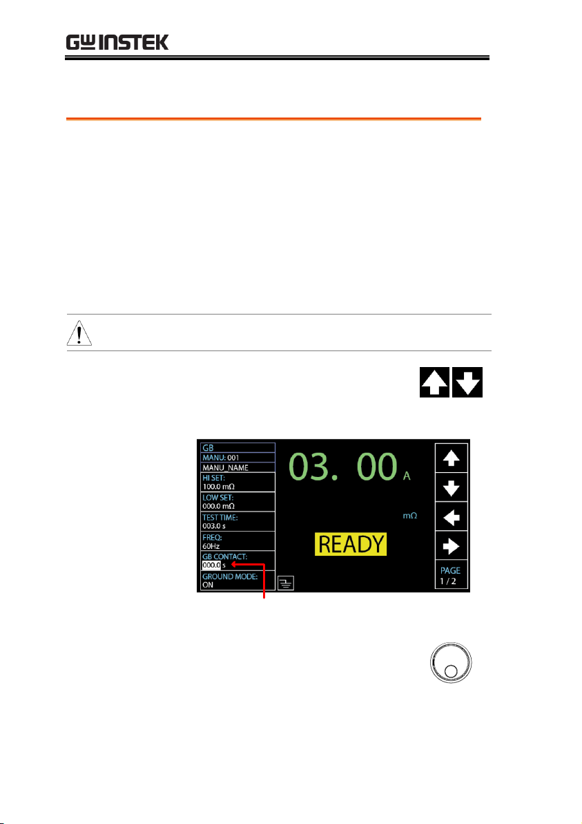
Background
Basically, GB test has no ramp up time and thus
starts from the set test time by user directly.
However, due to some cases where a buffer
time before test time is in fact required for GB
test, e.g., in conveyor where DUTs are tested for
GB by batches and certain buffer duration
needed for test leads or jigs connecting with
DUTs, the GB CONTACT setting practically
allows user to apply to customized scenarios
when necessary occurs.
Note
GB CONTACT setting is only applicable to GB test.
Steps
1. Press the UP / DOWN arrow soft-
keys to bring the cursor to the GB
CONTACT setting.
GB CONTACT cursor
2. Use the scroll wheel to set the
value of GB CONTACT
GB CONTACT
000.0 s ~ 999.9 s
Setting GB Contact
68

OPERATION
GB CONTACT
Duration
Indicator
After every parameter including GB CONTACT is
well set, press START to begin the GB test. A
section at the lower right corner of display shows
the counting duration of GB CONTACT, which will
run to the set value followed by the test time. See
the screenshot shown below.
GB CONTACT duration indicator
69

GPT-10000 Series User Manual
Background
The Zeroing function is used to determine the
resistance of the test leads for GB and CONT
tests. When a ZERO CHECK is performed, the
reference is automatically set to the measured
resistance of the test leads.
Note
ZERO CHECK setting is only applicable to both GB
and CONT tests.
Steps
1. Short the positive and negative alligator clips as
shown below.
2. Press the PAGE soft-key to move to
the 2/2 page where ZERO CHECK
setting appears for GB testing.
As for CONT, ZERO CHECK setting
shows in the 1/1 page directly.
3. Press the UP / DOWN arrow soft-
keys to bring the cursor to the ZERO
CHECK setting. When selecting ON,
the ZERO CHECK indicator will be
shown on the display.
Zero Check for the Test Leads
70

OPERATION
ZERO CHECK cursor ZERO CHECK indicator
4. Press the START button to perform
the zero check. The resistance of
the test leads, after the ZERO
CHECK has finished, will be
added into the REF VALUE field
as the display shown below.
Resistance of the test leads
Note
Remember to replace the test leads to the proper
position on the DUT before testing.
71

GPT-10000 Series User Manual
FAIL – GBI LOW
If SOURCE H/L terminals are open or poorly
connected, the FAIL – GBI LOW status will appear
on the screen. Please re-check the connection of
SOURCE H/L terminals again.
FAIL – GBI LOW status
REF VALUE = 0
Press STOP button to exit and the
resistance of test leads were not
properly added into the REF VALUE,
which shows 000.0 mΩ as shown
below. Re-check the connection of
SOURCE H/L terminals and press
START button again to proceed to the
ZERO CHECK procedure.
REF VALUE = 0
72

OPERATION
Background
When GROUND MODE is set to ON, the GPT10000 grounds the return terminal to the
ground. This mode is best for DUTs that are
grounded to an earth ground by their chassis,
fixtures or operation environment. This mode
measures the potential of the HIGH VOLTAGE
terminal with respect to earth ground. This
means that additional noise which leaks to
earth ground will also be measured. This is the
safest testing mode, though potentially not as
accurate.
When GROUND MODE is set to OFF, the
return terminal is floating with respect to the
earth ground. This mode is for DUTs that are
floating and not directly connected to an earth
ground. This is more accurate than when
GROUND MODE is set to ON as less noise will
be measured. For this reason, this testing mode
is able to measure with better stability.
ACW/DCW, GROUND MODE ON, DUT grounded
Setting the Grounding Mode
73

GPT-10000 Series User Manual
ACW/DCW, GROUND MODE OFF, DUT floating
Note
If the current value, which results from comparison
between I1 and I2 current, is above 3mA, once user
unexpectedly touches the DUT, the GFCI, Ground
Fault Circuit Interrupter, function activates and
output will be stopped immediately so that
protection mechanism will be well triggered at
once.
IR, GROUND MODE ON, DUT grounded
74

OPERATION
IR, GROUND MODE OFF, DUT floating
GB, GROUND MODE ON, DUT grounded
GB, GROUND MODE OFF, DUT floating
75

GPT-10000 Series User Manual
Cont., GROUND MODE ON, DUT grounded
Note
In terms of Continuity test, it is compulsory to
ground the DUT and thus GROUND MODE is ON.
Warning
When GROUND MODE is set to OFF, the DUT,
fixtures or connected instrumentation cannot be
grounded. This will short circuit the internal
circuitry during a test.
For ACW and DCW tests, if it is not known whether
the DUT test setup is grounded or not, always set
GROUND MODE to ON.
Only set GROUND MODE to OFF when the DUT
is floating electrically.
Steps
1. Press the PAGE soft-key to move to
the 2/3 page where GROUND
MODE setting appears for ACW
and DCW.
As for IR and GB, the GROUND
MODE setting shows in the 1/2 page.
2. Press the UP / DOWN arrow soft-
keys to bring the cursor to the
GROUND MODE setting.
76

OPERATION
GROUND MODE cursor
3. Use the scroll wheel to set the
GROUND MODE.
GROUND MODE
OFF, ON
4. The GROUND MODE icon on the display
changes accordingly.
GROUND MODE ON
GROUND MODE OFF
Note
Under the IR test mode, when GROUND MODE is
ON but test time is se t < 0.5s, the error message
“TEST TIMR<0.5s” will be shown, by which user is
not able to start the IR test mode unless the test
time is reset to > 0.5s. Refer to page 45 for how to
set the test time manually.
GROUND MODE ON Error Message Prompts
0.3 s
Test Time
77

GPT-10000 Series User Manual
Background
The CONTACT CHK function is used to
determine if open circuit or short circuit occurs
between the test leads and DUT under the
ACW, DCW and IR tests. Before activating this
function, it is first required to define a reference
value along with relevant thresholds, for which
refer to page 161.
Note
CONTACT CHK setting is only applicable to ACW,
DCW and IR test modes.
Steps
1. After well setting up the test leads connection
with DUT, refer to page 161 for how to define a
reference value and relevant thresholds firstly.
2. Press the PAGE soft-key to move to
the 3/3 page where CONTACT
CHK setting appears for ACW,
DCW and IR tests.
3. Press the UP / DOWN arrow soft-
keys to bring the cursor to the
CONTACT CHK and turn it ON.
CONTACT CHK ON
Setting Contact Check
78

OPERATION
4. After pressing the START button,
the GPT-10000 unit will perform
the CONTACT CHK before
running a MANU test. If the
measured current is lower than the
reference value by user-defined
percentage, the “OPEN” status
appears on the screen. While the
measured current is higher than
the reference value by user-defined
percentage, the “SHORT” status
appears instead.
OPEN
Status
OPEN Status detected
SHORT
Status
SHORT Status detected
79

GPT-10000 Series User Manual
Background
A test can be run when the tester is in READY
status.
Note
The tester cannot start to run a test under the
following conditions:
A protection setting has been tripped; when a
protection setting has been tripped the
corresponding error message is displayed on
the screen. See page 238 for a comprehensive
list of the all the setting errors.
The INTERLOCK function is ON and the
Interlock key is not inserted in the signal I/O
port (page 130).
The STOP signal has been received remotely.
If Double Action is ON, ensure the START
button is pressed immediately after the STOP
button (<0.5s).
Note
When a test is running the voltage output
cannot be changed, unless the test is under the
special manual mode. See page 90 for details.
Steps
1. Ensure the tester is in READY
status for the test to come.
Page 33
Running a MANU Test
80

OPERATION
READY status
2. Press the START button when the
tester is in the READY status. The
manual test starts accordingly and
the tester goes into the TEST status.
TEST status
3. The test will start by showing the ongoing ramp
up time followed by the ongoing test time and
the ongoing ramp down time. The test will
continue until the test is finished or stopped.
81

GPT-10000 Series User Manual
RAMP UP TIME
Ongoing RAMP UP TIME
TEST TIME
Ongoing TEST TIME
RAMP DOWN
TIME
Ongoing RAMP DOWN TIME
Note
RAMP DOWN time only appears when user
has activated it. See page 49 for details.
82

OPERATION
ACW Example
Measured Current
Test Voltage
DCW Example
Measured Current
Test Voltage
IR Example
Measured Resistance
Test Voltage
83

GPT-10000 Series User Manual
GB Example
Measured Resistance
Test Current
CONT Example
Measured Resistance
Test Current
Stop the Test
1. To stop the test at any time when it
is running, press the STOP button.
The test will stop immediately.
When the STOP button is pressed,
a judgment is not made and the
tester will restore to READY status.
Note
Do not touch any terminals, test leads or any other
connections when the test is on.
84

OPERATION
Background
If the test is allowed to run to completion (the
test is not stopped or a protection setting is not
tripped) then the tester will judge the test as
either PASS or FAIL.
Note
The test will be judged PASS when:
The HI SET and LO SET limits have not been
tripped during the test time.
The test will be judged FAIL when:
Either the HI SET or LO SET limit has been
tripped during the test time.
A protection setting has been tripped during
the test time. See page 238 for a list of error
messages.
PASS Judgment
1. When the test is judged as PASS,
PASS will be displayed on screen,
the buzzer will sound and the
PASS indicator will be lit green.
PASS Judgment
PASS / FAIL MANU Test
85

GPT-10000 Series User Manual
2. The tester will immediately restore back to the
READY status after PASS judgment. However,
if the PASS HOLD is activated, PASS judgment
will persist until the set duration of PASS
HOLD is fully met. Refer to page 63 for details.
In addition, pressing the STOP
button during the set duration of
PASS HOLD can return to READY
status immediately.
Note
The START button is disabled when the buzzer is
beeping.
PASS Timing
Diagrams
The timing diagrams below show the ACW, DCW,
IR, GB and CONT timing for the START status,
TEST status and PASS judgment.
ACW PASS
Timing
RAMP DOWN
& DISCHARGE
Output V
time
START
TEST
PASS
RAMP UPTEST TIME
DCW PASS
Timing
Output V
time
START
TEST
PASS
RAMP UPTEST TIME
RAMP DOWN
& DISCHARGE
86

OPERATION
IR PASS Timing
Output V
time
START
TEST
PASS
RAMP UPTEST TIME
RAMP DOWN
& DISCHARGE
GB PASS Timing
START
PASS
Output I
TEST
Contact
RAMP Test
time
Time0.1s 0.1s
UP Time
CONT PASS
Timing
Output I
time
START
TEST
PASS
Test Time
FAIL Judgment
1. When the test is judged as FAIL,
FAIL will be displayed on screen,
the buzzer will sound and the
FAIL indicator will be lit red.
As soon as a test is judged FAIL,
power is cut from the terminals.
87

GPT-10000 Series User Manual
FAIL Judgment
2. The FAIL judgment will be held on
the display until the STOP button
is pressed. Pressing the STOP
button will return the tester back to
the READY status.
FAIL Timing
Diagrams
The timing diagrams below show the ACW, DCW,
IR, GB and CONT timing for the START status,
TEST status and FAIL judgment.
ACW FAIL Timing
DISCHARGE
Output V
time
START
TEST
FAIL
RAMP UPTEST TIME
88

OPERATION
DCW FAIL Timing
DISCHARGE
Output V
time
START
TEST
FAIL
RAMP UPTEST TIME
IR FAIL Timing
DISCHARGE
Output V
time
START
TEST
FAIL
RAMP UPTEST TIME
GB FAIL Timing
START
FAIL
Output I
TEST
Contact
RAMP Test
time
Time0.1s 0.1s
UP Time
CONT FAIL
Timing
Output I
time
START
TEST
FAIL
Test Time
89

GPT-10000 Series User Manual
Special Test
Mode Overview
When MANU number 000 is selected, the
special test mode is activated. Under the special
test mode, the voltage can be changed during a
test in real time (ACW, DCW only). The test
function can also be changed when in READY
status, unlike under normal operation.
Separate settings can be saved under the special
test mode for each of the testing functions:
ACW, DCW, IR, GB and CONT. This means
different test setups for ACW, DCW, IR, GB
and CONT can be saved within the MANU
number 000 concurrently.
Steps
1. Choose MANU number 000 to
enter the special test mode.
Page 41
2. The settings of a previous test can
be loaded by pressing the
corresponding soft-keys on the
front panel.
For example, if you are currently in
DCW mode, pressing the ACW
key will load the ACW settings
that were previously stored in the
special manual mode.
Special MANU Test Mode (000)
90

OPERATION
3. Set all the necessary parameters for
a test and save.
Note: A different test setup can be
saved for each test function (ACW,
DCW, IR, GB and CONT). Below is
an example of ACW function in
special manual mode.
Pages 42 ~
73
Special MANU Number 000
Running the Test
1. In special test mode (000), tests are
started and stopped in the same
way as for the normal manual test
mode. See page 78 for details.
2. If required, the scroll wheel can be
used to set the voltage level in realtime as the test is running under
either ACW or DCW mode.
ACW
DCW
0.050kV ~ 5kV
0.050kV ~ 6kV
Results
Test judgments are the same as
those for the normal manual tests.
Please see the PASS/FAIL MANU
Test section for details.
Page 85
91
GPT-10000 Series User Manual
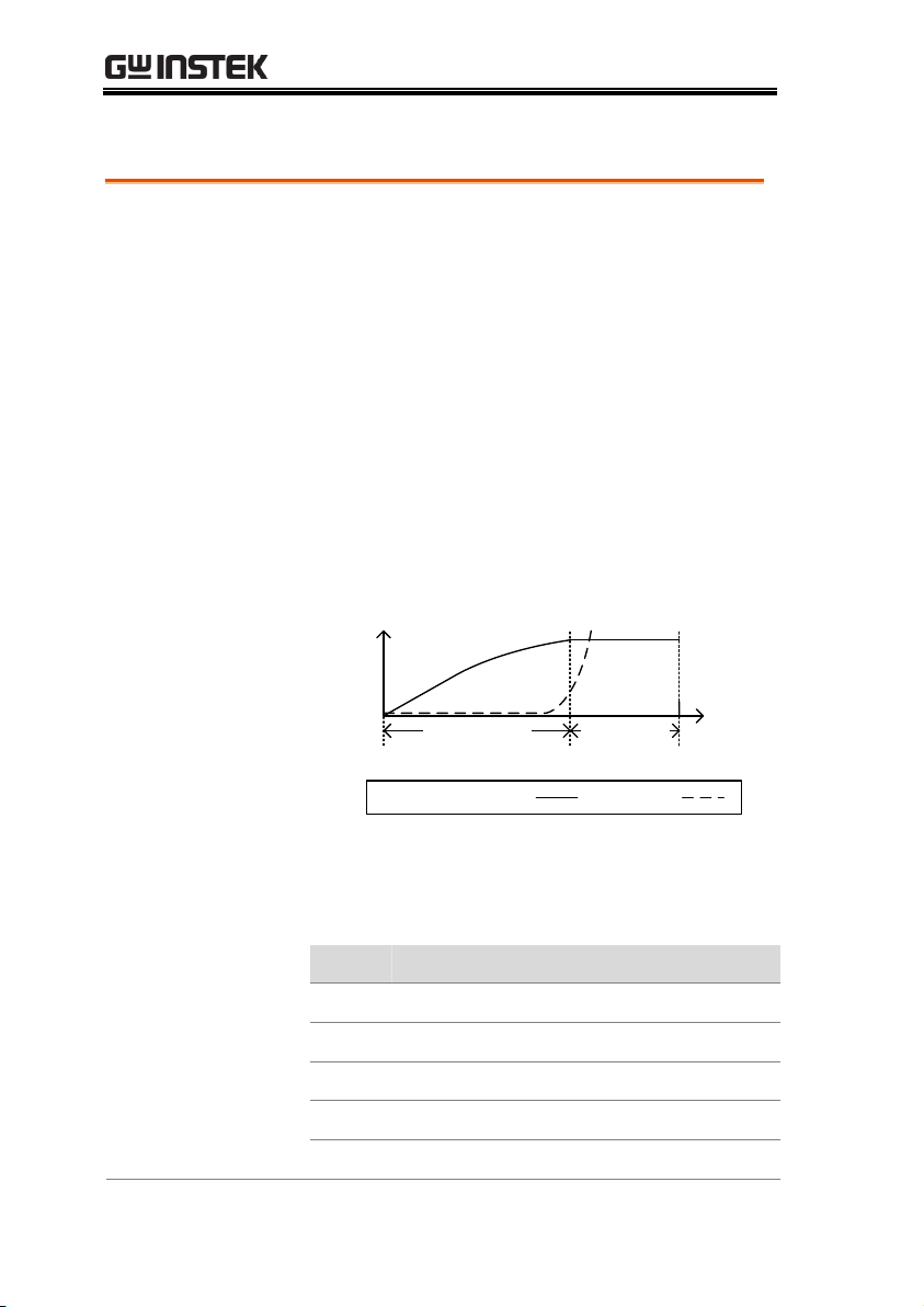
Sweep Function
Overview
The GPT-10000 Series has access to the sweep
mode function, which creates a graph of one of
the ACW, DCW, IR, GB or CONT tests in either
Manual test or the special MANU mode. The
graph will plot the output voltage, current or
resistance versus time. After the test has been
completed, the test current, voltage or
resistance at any point in time can be fetched
and viewed in the graph.
Below is an example of the resultant sweep plot
of a DCW test where a DC voltage is ramped up
to a user-defined level until the HI SET current
level has been tripped or the test time runs out.
Test V
Meas. I
time
Start time
RAMP TIME
Legend: Voltage: Current
TEST time
Voltage
Current
The test items that are plotted on the sweep
graph depend on the type of test that is
performed.
TEST
Graph Test Items
ACW
Measured voltage, measured current (V, I)
DCW
Measured voltage, measured current (V, I)
IR
Measured voltage, measured resistance (V, R)
GB
Measured current, measured resistance (I, R)
CONT
Measured current, measured resistance (I, R)
Sweep Function
92

OPERATION
Steps of View
Sweep Graph
1. When a test has finished, press
the corresponding button, e.g.,
DCW button for DCW test, to
view the result of the sweep in
an intuitive graph.
Graph Test Items:
TEST
GREEN
BLUE
ACW
Measured voltage
Measured current
DCW
Measured voltage
Measured current
IR
Measured voltage
Measured resistance
GB
Measured current
Measured resistance
CONT
Measured current
Measured resistance
DCW Sweep
Graph Example
Cursor
Measured Current
(READ I in Blue)
Measured Voltage
(READ V in Green)
The values of point by cursor
93

GPT-10000 Series User Manual
2. Use the scroll wheel to move the
cursor on the time axis (red
highlight in x-axis). The measured
values on the green and blue lines
at that particular point in time are
shown within the table below
(orange highlight). Also, the test
function along with the test number
is clearly shown within the table.
The HI in y-axis (yellow highlight)
along with the dotted line in red
indicates the HI SET value and the
point of tripped time.
Turn Pages
3. The resultant graph will be over 1 page
when test time is beyond 650 steps (the
interval of each step is 0.1s). In this
case, press PAGE soft-key to switch
among each page for full graphs.
Fast-forward
4. Press the MOVE soft-key before
moving the cursor to fast-forward
steps by 10 times (x 10), which is
practical when steps are many. Press
the MOVE soft-key again to return
back to the normal “x 1” speed.
Exit the Results
Graph
To exit the sweep graph, press
the corresponding button again
to return back to Manual test.
94

OPERATION
Automatic Tests
This section describes how to create, edit and run automatic tests.
Automatic tests allow you to link up to 10 different MANU tests
and run them sequentially within a single AUTO test. Each stored
MANU test is used as a test step when creating an AUTO test. In
addition, up to 5 groups of AUTO test can be interconnected
together to present an ever-advanced AUTO tests.
Choose/Recall an AUTO Test→ from page 96
Creating an AUTO Test File Name → from page 97
Adding a Step to the AUTO Test → from page 98
Continuous AUTO Tests → from page 100
AUTO Test Page Editing → from page 102
Running an Automatic Test → from page 107
Automatic Test Results → from page 113
Before operating the GPT-10000 please read the safety precautions
as outlined in the Set Up chapter on page 22.
95

GPT-10000 Series User Manual
Background
The tester must first be put into AUTO mode to
create or run automatic tests.
Up to 100 automatic tests can be saved or
recalled.
Steps
1. If the tester is in MANU or
SYSTEM mode, press the AUTO
key on the front panel. This will
put the tester into Auto mode.
2. After entering the AUTO mode,
first use the scroll wheel to choose
the AUTO number.
AUTO #
001~100
AUTO number cursor READY status
Note
The AUTO number can only be chosen
in READY status. If the status is either
PASS or FAIL, press the STOP button
to restore back to the READY status.
Choose/Recall an AUTO Test
96

OPERATION
Background
Each automatic test can have a user-defined test
file name (Default: AUTO_NAME) up to 10
characters long. See the character list below for
the allowed characters.
Character List
0 1 2 3 4 5 6 7 8 9
W X Y ZM VO P RQ T USNLA B C D E F G H I J K
w x y zm vo p rq t usnla b c d e f g h i j k
_
Steps
1. Use the LEFT/RIGHT arrow soft-
keys to move the cursor to the
AUTO_NAME (default name) field.
The characters table will appear in
the right hand accordingly.
AUTO name cursor Character Table
2. Use the scroll wheel to scroll
through the available characters.
3. Press the LEFT / RIGHT arrow soft-
keys to move the cursor to the next
character.
Creating an AUTO Test File Name
97

GPT-10000 Series User Manual
4. The AUTO test file name is set when the
current AUTO test is saved or when the cursor
is moved to another setting.
Background
Up to 10 MANU tests (steps) can be added to
an automatic (AUTO) test. Each step is added
in a sequential order.
Steps
1. Press the DOWN arrow key to
bring the cursor to the MANU
STEP number.
MANU STEP number cursor
2. Use the scroll wheel to choose a
MANU STEP number to add to the
automatic test.
MANU STEP number
001~100, CON
CON
It indicates that this group of AUTO test
can be connected with the next group.
Refer to page 100 for more details.
Adding a Step to the AUTO Test
98

OPERATION
3. Further press the DOWN arrow
key followed by using the scroll
wheel to choose another MANU
STEP number to add to the
automatic test.
MANU STEP number cursor (2nd)
4. Repeat the previous steps for any other MANU
tests that you wish to add to the automatic test.
99

GPT-10000 Series User Manual
Background
As mentioned previously, up to 10 MANU
steps can be grouped to form an AUTO test and
user can designate each step from MANU step
number 1 to 100 for an AUTO test. However, it
is available to interconnect different AUTO
tests together to present a series of AUTO tests.
Steps
1. Follow the steps of “Adding a Step to the
AUTO Test” in page 98 first. See the example
below where 5 MANU steps have been
added into the AUTO-001 group.
2. Press the DOWN arrow key to
bring the cursor to the next MANU
STEP field followed by using the
scroll wheel to choose CON from
the MANU STEP options.
CON is chosen from MENU STEP
Continuous AUTO Tests
100
 Loading...