

Page 1

Programmable AC/DC Power Source
ASR-3000 Series
PROGRAMMING MANUAL
Rev. A
ISO-9001 CERTIFIED MANUFACTURER
Page 2

This manual contains proprietary information, which is protected by
copyright. All rights are reserved. No part of this manual may be
photocopied, reproduced or translated to another language without
prior written consent of Good Will company.
The information in this manual was correct at the time of printing.
However, Good Will continues to improve products and reserves the
rights to change specification, equipment, and maintenance
procedures at any time without notice.
Good Will Instrument Co., Ltd.
No. 7-1, Jhongsing Rd., Tucheng Dist., New Taipei City 236, Taiwan.
Page 3

Table of Contents
Table of Contents
SAFETY INSTRUCTIONS .................................................. 4
GETTING STARTED .......................................................... 8
ASR-3000 Series Overview ..................... 9
Appearance .......................................... 12
REMOTE CONTROL ....................................................... 20
Interface Configuration ........................ 21
Command Syntax ................................. 41
Command List ..................................... 45
Status Register Overview ................... 127
Error List ........................................... 143
APPENDIX .................................................................... 152
Factory Default Settings ..................... 152
INDEX .......................................................................... 157
3
Page 4

ASR-3000 Programming Manual
WARNING
Warning: Identifies conditions or practices that
could result in injury or loss of life.
CAUTION
Caution: Identifies conditions or practices that
could result in damage to the ASR-3000 or to other
properties.
DANGER High Voltage
Attention Refer to the Manual
Protective Conductor Terminal
Earth (ground) Terminal
SAFETY INSTRUCTIONS
This chapter contains important safety
instructions that you must follow during
operation and storage. Read the following before
any operation to ensure your safety and to keep
the instrument in the best possible condition.
Safety Symbols
These safety symbols may appear in this manual or on the
instrument.
4
Page 5

SAFETY INSTRUCTIONS
Do not dispose electronic equipment as unsorted
municipal waste. Please use a separate collection
facility or contact the supplier from which this
instrument was purchased.
General
Guideline
CAUTION
Do not place any heavy object on the ASR-3000.
Avoid severe impact or rough handling that
leads to damaging the ASR-3000.
Do not discharge static electricity to the ASR-
3000.
Use only mating connectors, not bare wires, for
the terminals.
Do not block the cooling fan opening.
Do not disassemble the ASR-3000 unless you are
qualified.
If the equipment is used in a manner not
specified by the manufacturer, the protection
provided by the equipment may be impaired.
Safety Guidelines
5
Page 6

ASR-3000 Programming Manual
Power Supply
WARNING
AC Input voltage range:
200 ~ 240 Vac
Frequency: 47 ~ 63 Hz
To avoid electrical shock connect the protective
grounding conductor of the AC power cord to
an earth ground.
The power switch that is included in the
instrument is not considered a disconnecting
device.
The permanently connected power input is used
as the disconnecting device and shall remain
readily operable.
a. A switch or circuit-breaker must be included
in the installation
b. It must be suitably located and easily reached
c. It must be marked as the disconnecting
device for the equipment.
d. It shall be located near the equipment
Do not position the equipment so that it is
difficult to operate the disconnecting device.
Ask for professional technician for installation.
It requires 200Vac input condition and the
maximum input current [15A (ASR-3200), 22.5A
(ASR-3300), 30A (ASR-3400)], which conforms
to cord diameter by local regulations.
Breaker, of which the specification is required to
larger than 20A (ASR-3200), 30A (ASR-3300),
40A (ASR-3400) individually, should be in the
near proximity of unit.
6
Page 7

SAFETY INSTRUCTIONS
Cleaning the ASR3000
Disconnect the circuit-breaker or permanently
connected power input before cleaning.
Use a soft cloth dampened in a solution of mild
detergent and water. Do not spray any liquid.
Do not use chemicals containing harsh material
such as benzene, toluene, xylene, and acetone.
Operation
Environment
Location: Indoor, no direct sunlight, dust free,
almost non-conductive pollution (Note below)
Relative Humidity: 20%~ 80%, no condensation
Altitude: < 2000m
Temperature: 0°C to 40°C
(Pollution Degree) EN 61010-1:2010 specifies the pollution degrees
and their requirements as follows. The ASR-3000 falls under degree 2.
Pollution refers to “addition of foreign matter, solid, liquid, or
gaseous (ionized gases), that may produce a reduction of dielectric
strength or surface resistivity”.
Pollution degree 1: No pollution or only dry, non-conductive
pollution occurs. The pollution has no influence.
Pollution degree 2: Normally only non-conductive pollution
occurs. Occasionally, however, a temporary conductivity caused
by condensation must be expected.
Pollution degree 3: Conductive pollution occurs, or dry, non-
conductive pollution occurs which becomes conductive due to
condensation which is expected. In such conditions, equipment
is normally protected against exposure to direct sunlight,
precipitation, and full wind pressure, but neither temperature
nor humidity is controlled.
Storage
environment
Location: Indoor
Temperature: -10°C to 70°C
Relative Humidity: ≤90%, no condensation
Disposal
Do not dispose this instrument as unsorted
municipal waste. Please use a separate collection
facility or contact the supplier from which this
instrument was purchased. Please make sure
discarded electrical waste is properly recycled to
reduce environmental impact.
7
Page 8

ASR-3000 Programming Manual
ASR-3000 series
ASR-3000 Series Overview ..................... 9
Series lineup ......................................................... 9
Main Features ...................................................... 9
Accessories ........................................................... 10
Appearance ........................................... 12
Front Panel ........................................................... 12
Rear Panel ............................................................ 17
GETTING STARTED
This chapter describes the ASR-3000 power
supply in a nutshell, including its main features
and front / rear panel introduction.
8
Page 9

GETTING STARTED
Model Name
Power Rating
Max. Output Current
Max. Output Voltage
ASR-3200
2000 VA
20 / 10 A
400 Vrms / 570 Vdc
ASR-3300
3000 VA
30 / 15 A
400 Vrms / 570 Vdc
ASR-3400
4000 VA
40 / 20 A
400 Vrms / 570 Vdc
Performance
Maximum AC output voltage is 400 Vrms
Maximum DC output voltage is 570 Vdc
Maximum output frequency is 999.9 Hz in AC
mode
Supported AC+DC waveform application
DC full capacity output ability
Output voltage total harmonic distortion is less
than 0.5% at all frequency
Crest factor reached 6 times high
ASR-3000 Series Overview
Series lineup
The ASR-3000 series consists of 3 models, the ASR-3200, ASR-3300
and ASR-3400, differing only in capacity. Note that throughout the
user manual, the term “ASR-3000” refers to any of the models,
unless stated otherwise.
Main Features
9
Page 10

ASR-3000 Programming Manual
Features
Include sine, square, triangle, arbitrary and DC
output waveforms
Variable voltage, frequency and current limiter
Harmonic voltage and current analysis ability
Excellent and feature-rich measurement
capacity
Sequence and simulate function
External input amplification
AC line synchronized output
Preset memory function
USB memory support
Remote sense
OCP, OPP and OTP protection function
Interface
Built-in LAN, USB host, USB device, RS232 and
GPIB interface
External control I/O
External signal input
Standard
Accessories
Part number
Description
CD ROM
User manual, programming
manual
82GW1SAFE0M*1
Safety guide
62SR-3K0SC101
Input terminal cover
62SR-3K0SC201
Output terminal cover include
remote sensing
GRA-442-E
Rack mount adapter (EIA)
Accessories
Before using the ASR-3000 power source unit, check the package
contents to make sure all the standard accessories are included.
10
Page 11

GETTING STARTED
GTL-246
USB CABLE (USB 2.0 Type AType B Cable, Approx. 1.2M)
Factory
Installed
Options
Part number
Description
Optional 1
European Output Socket
Optional
Accessories
Part number
De scription
GPW-005
Power Cord SJT 12AWG/3C, 3m
Max Length, 105°C, RNB5-8*3P,
RNB3-4*3P UL/CSA Type
GPW-006
Power Cord H05W-F
1.5mm2/3C, 3m Max Length,
105°C, RNB1-5*3P, RNBL2-4*3P
VDE Type
GPW-007
Power Cord VCT 3.5mm2/3C,
3m Max Length, 105°C, RNB58*3P, RNB3-4*3P PSE Type
GRA-442-J
Rack mount adapter (JIS)
GTL-137
Output power wire
(Load wire_10AWG: 50A, 600V)
(Sense wire_16AWG: 20A, 600V)
GTL-232
RS232C cable, approx. 2M
GTL-248
GPIB Cable, approx. 2M
ASR-002
External Three Phase Control
Unit
APS-008
Air inlet filter
11
Page 12

ASR-3000 Programming Manual
1 2 3 4 5 6 7 8 9 A
B
C
D
E
F
G
HIJKM L
Item Index
Description
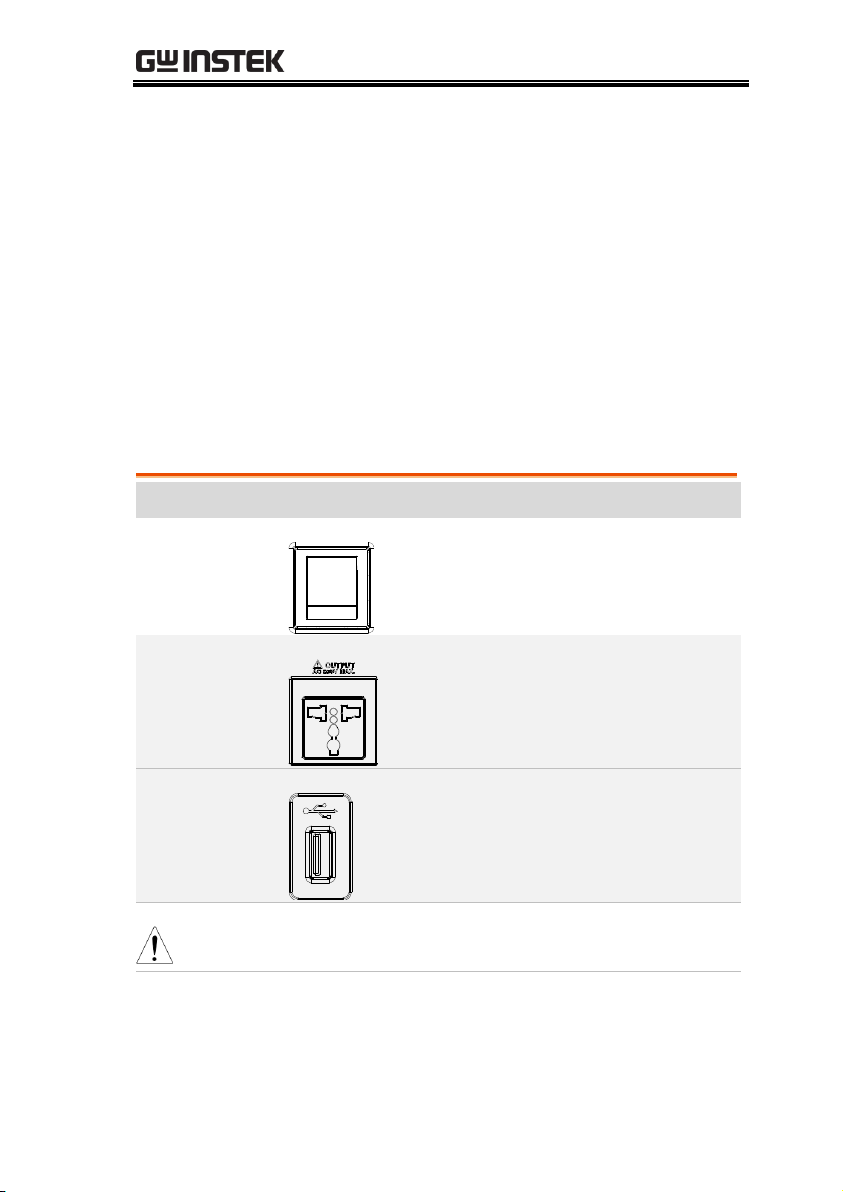
1
Power switch button
2
Output Socket
3
USB interface connector (A Type)
4
LCD screen
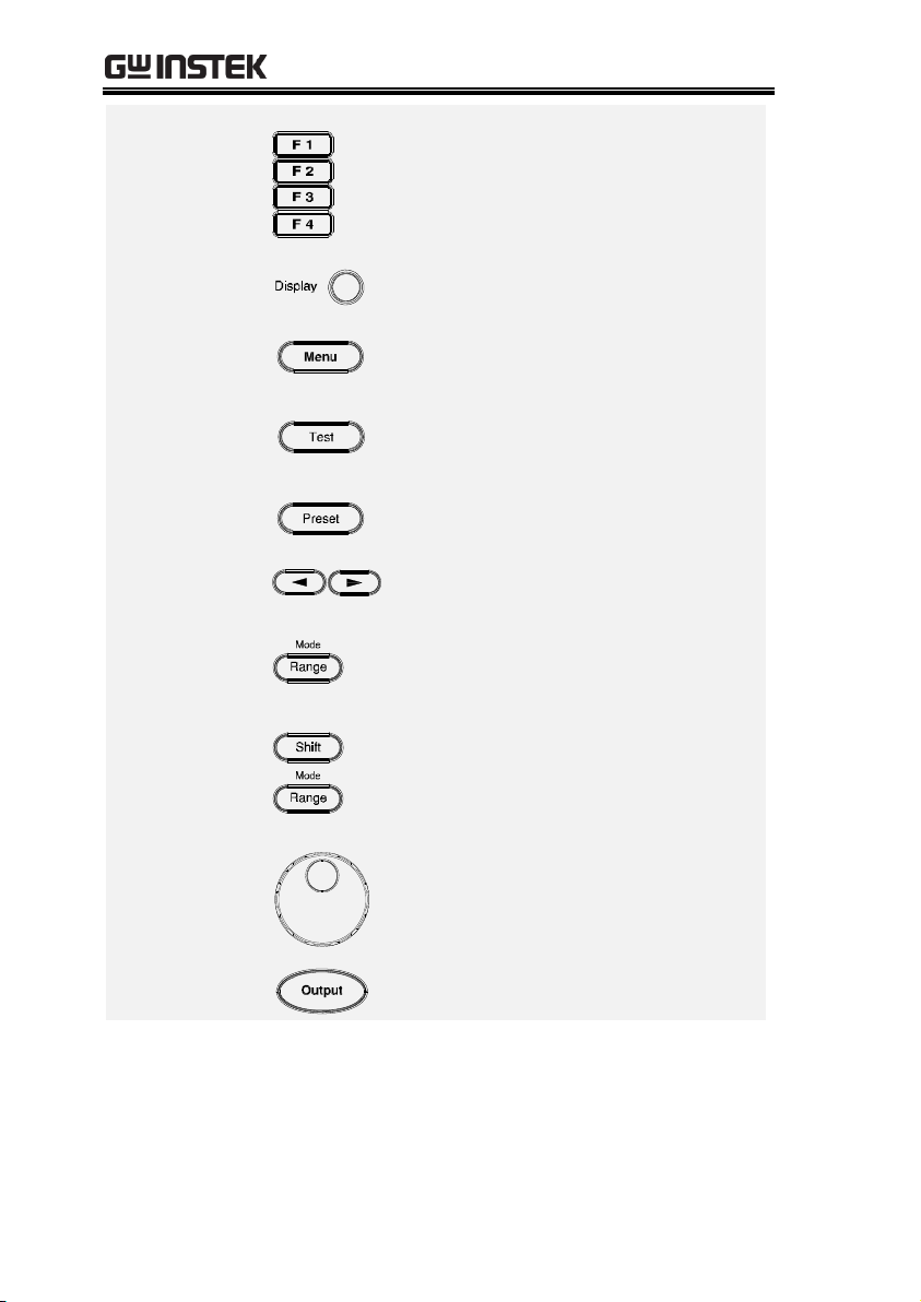
5
Function keys (blue zone)
6
Display mode select key
7
Menu key
8
Test key
9
Preset key
A
Arrow keys
B
Range key/Output mode key
C
Scroll wheel
Appearance
Front Panel
12
Page 13
GETTING STARTED
D
Output key
E
Shift key
F
Cancel key
G
Enter key
H
Irms/IPK-Limit button
I
Lock/Unlock button
J
F/F-Limit button
K
V/V-Limit button
L
Numerical Keypad with additional “Shift + key”
shortcut functions (green zone)
M
Air inlet
Item
Description
Power Switch
Turn on the mains power
Output Socket
Output voltage socket, which has 2
versions in accordance with different
regions: Universal and European types,
in front panel.
USB A Port
The USB port is used for data transfers
and upgrading software. Also, it is
available for screenshot hardcopy in
association with the Hardcopy key.
Note
It supports FAT32 format with maximum 32G storage
only.
LCD Screen
Displays the setting and measured
values or menu system
13
Page 14
ASR-3000 Programming Manual
Function Keys
Assigned to the functions displayed on
the right side of the screen.
Display Mode
Select Key
Selects between standard, simple and
harmonic analysis mode.
Menu Key
Enters the Main menu or goes back to
one of the display modes.
Test Key
Puts the instrument into the Sequence
and Simulation control mode.
Preset Key
Puts the instrument into Preset mode.
Arrow Keys
The arrow keys are used to select the digit
power of a value that is being edited.
Range Key
Switches between the 100V, 200V and
AUTO ranges
Output Mode
+
Selects between the AC+DC-INT, ACINT, DC-INT, AC+DC-EXT, AC-EXT,
AC+DC-ADD, AC-ADD, AC+DC-Sync and
AC-Sync modes.
Scroll Wheel
Used to navigate menu items or for
increment/decrement values one step at
a time.
Output Key
Turns the output on or off.
14
Page 15

GETTING STARTED
Shift Key
Turns on the shift state, which enables
shortcut operations with an icon
indicated on the top status bar. The shift
state, which allows continuous shortcut
operations, is kept until another press
on shift key again.
Note
When performing shortcut operations, press shift key
followed by another shortcut function key. Do Not
press both shift key and shortcut function key
simultaneously.
Cancel Key
Used to cancel function setting menus
or dialogs.
Enter Key
Confirms selections and settings.
Irms
Used for setting the maximum output
current.
IPK-Limit
+
Used to set the peak output current limit
value.
Lock/Unlock Key
Used to lock or unlock the front panel
keys except output key. Simply press to
lock, whilst long press to unlock.
F Used for setting the output frequency
(DC mode N/A).
F-Limit
+
Used for setting the output frequency
limit value (DC mode N/A).
V Used for setting the output voltage.
15
Page 16

ASR-3000 Programming Manual
V-Limit
+
Used for setting the output voltage limit
value.
Keypad
Used to input power of a value directly.
The key is used to input decimal /
plus or minus.
On Phase
+
Sets the on phase for the output voltage.
Off Phase
+
Sets the off phase for the output voltage.
Output
Waveform
+
Selects between the Sine, Square,
Triangle and ARB 1~16 waveforms
(not available for DC-INT, AC+DC-EXT
and AC-EXT).
Local Mode
+
Switches operation back to local mode
from remote mode.
IPK CLR
+
Used to clear peak output current value.
ALM CLR
+
Clears alarms.
Hardcopy Key
+
Used to take a screenshot. Make sure an
USB flash disk in well inserted before
the action.
Air Inlet
Air inlet for cooling the inside of the
ASR-3000 series.
16
Page 17

Rear Panel
13 2
4 5 6 7 8 9
Item Index
Description
1
Line input terminal
2
Front panel output socket circuit breaker
3
Output terminal with remote sensing input terminal
4
External I/O connector
5
GPIB connector
6
USB interface connector (B Type)
7
Ethernet (LAN) connector
8
RS232 connector
9
External signal input/
External synchronized signal input
GETTING STARTED
17
Page 18

ASR-3000 Programming Manual
Item
Description
AC Power Input
terminal
AC inlet
(M4 screw type, 8 ~ 22 AWG)
Circuit Breaker
When front panel output socket
output current reaches 15A, the
circuit breaker will be activated
automatically to cut off output. Press
the button to reset the function.
Output Terminal
with Remote
Sensing Input
terminal
L, N, : Output voltage terminal
(M4 screw type, 8 ~ 22 AWG)
+S, -S: Remote sensing input
terminal is for compensation of
load wire voltage drop.
External Control
I/O Connector
Used to control ASR-3000 externally
by using the logic signal and
monitor Sequence function status.
GPIB Connector
The GPIB connector for
controlling the ASR-3000 remotely.
USB
USB port for controlling the ASR3000 remotely.
Ethernet Port
The Ethernet port is used for
remote control.
RS232C
Connector
The RS232C connector for
controlling the ASR-3000 remotely.
18
Page 19

GETTING STARTED
External Signal
Input Connector
Synchronizing the output frequency
with this external input signal for
SYNC or outputting the amplified
external signal with this external
input signal for EXT and ADD.
19
Page 20

ASR-3000 Programming Manual
Interface Configuration .......................... 21
Configure Ethernet Connection ........................ 21
USB Remote Interface ......................................... 22
USB Remote Control Function Check .............. 23
RS-232 Remote Interface .................................... 24
RS232 Remote Control Function Check ........... 26
Using Realterm to Establish a Remote
Connection ........................................................... 28
GPIB Remote Interface ....................................... 31
GPIB Function Check ......................................... 32
Web Server Remote Control Function Check . 35
Socket Server Function Check ........................... 36
Command Syntax ................................... 41
Command List ....................................... 45
REMOTE CONTROL
This chapter describes basic configuration of
IEEE488.2 based remote control.
20
Page 21

REMOTE CONTROL
Ethernet
Parameters
MAC Address (display
only)
DHCP
IP Address
Subnet mask
Gateway
DNS address
DNS Server
Socket port fixed at 2268
Ethernet
Configuration
1. Connect a LAN cable from the PC
to the Ethernet port on the rear
panel.
LAN
2. Press the Menu key. The Menu
setting will appear on the display.
3. Use the scroll wheel to go to item 3, LAN and
press Enter.
4. If the LAN cable is installed correctly a
connection is active, the Connection Status will
show Online.
5. To automatically have the network assign an IP
address, set DHCP to ON. Otherwise set DHCP
to OFF to manually set the Ethernet settings.
DHCP
ON, OFF
Interface Configuration
Configure Ethernet Connection
The Ethernet interface can be configured for a number of different
applications. Ethernet can be configured for basic remote control or
monitoring using a web server or it can be configured as a socket
server.
The ASR-3000 supports both DHCP connections so the instrument
can be automatically connected to an existing network or
alternatively, network settings can be manually configured.
21
Page 22

ASR-3000 Programming Manual
6. If DHCP was set to OFF, configure the
remaining LAN parameters.
IP Address
Subnet Mask
Gateway
DNS Server
Socket Port
Note
Socket Port is fixed to 2268.
LAN configuration - 1
LAN configuration - 2
Exit
7. Press Exit[F4] to exit from the LAN
settings.
USB
Configuration
PC side connector
Type A, host
ASR-3000 side
connector
Rear panel Type B, slave
Speed
1.1/2.0 (full speed)
USB Class
CDC (communications device
class)
Steps
1. Connect the Type A-Type B USB
cable from the PC to the rear panel
USB B port.
USB Remote Interface
22
Page 23

REMOTE CONTROL
2. Press the Menu key. The Menu
setting will appear on the display.
3. Use the scroll wheel to go to item 4, USB Device.
4. If the connection is successful Connection Status
will change from Offline to Online.
Exit
5. Press Exit[F4] to exit from the rear
panel USB settings.
Functionality
Check
Invoke a terminal application such as Realterm.
ASR-3000 will appear as a COM port on the PC.
To check the COM settings in Windows, see the
Device Manager. For example, in Win7 go to
the Control panel → System → Hardware tab.
Note
If you are not familiar with using a terminal
application to send/receive remote commands via a
USB connection, please see page 28 for more
information.
Run this query command via the terminal after
the instrument has been configured for
USB remote control (page 22).
*IDN?
This should return the Manufacturer, Model
number, Serial number, and Software version
in the following format.
GW-INSTEK,ASR-XXXX,GXXXXXXXX,XX.XX
USB Remote Control Function Check
23
Page 24

ASR-3000 Programming Manual
Manufacturer: GW-INSTEK
Model number : ASR-XXXX
Serial number : GXXXXXXXX
Software version : XX.XX
Note
For further details, please see the programming
manual, available on the GW Instek web site @
www.gwinstek.com.
RS-232
Configuration
Connector
BD-9, male
Parameters
Baud rate, data bits, parity, stop
bits.
Pin Assignment
1
2345
6789
2: RxD (Receive data)
3: TxD (Transmit data)
5: GND
4, 6 ~ 9: No connection
Pin Connection
Use a Null Modem connection (RS-232C cable)
as shown in the diagram below.
ASR-3000 PC
RxDPin2 RxD Pin2
GNDPin5 GND Pin5
TxD Pin3
TxDPin3
Steps
1. Connect the RS-232C cable from
the PC to the rear panel RS-232
port.
RS-232 Remote Interface
24
Page 25

REMOTE CONTROL
2. Press the Menu key. The Menu
setting will appear on the display.
3. Use the scroll wheel to go to item 5, RS232C
and press Enter.
4. Set the RS232C relative settings.
Baud rate
1200, 2400, 4800, 9600(default),
19200, 38400, 57600, 115200,
Data bits
7 bits, 8 bits(default)
Parity
None(default), Odd, Even
Stop bits
1 bit(default), 2 bits
RS232C Configuration
Exit
5. Press Exit[F4] to exit from the
RS232C settings.
Note
The standard accessory does Not include RS232
data cable. Please purchase the additional GTL-232
which will meet your need for RS232 connection.
25
Page 26

ASR-3000 Programming Manual
Functionality
Check
Invoke a terminal application such as Realterm.
For RS-232, set the COM port, baud rate, stop
bit, data bit and parity accordingly.
To check the COM settings in Windows, see the
Device Manager. For example, in Win7 go to
the Control panel → System → Hardware tab.
Note
If you are not familiar with using a terminal
application to send/receive remote commands from
the serial port, please see page 28 for more
information.
Run this query command via the terminal after
the instrument has been configured for
RS-232 remote control (page 24).
*IDN?
This should return the Manufacturer, Model
number, Serial number, and Software version
in the following format.
GW-INSTEK,ASR-XXXX,GXXXXXXXX,XX.XX
Manufacturer: GW-INSTEK
Model number : ASR-XXXX
Serial number : GXXXXXXXX
Software version : XX.XX
RS232 Remote Control Function Check
26
Page 27

REMOTE CONTROL
Note
For further details, please see the programming
manual, available on the GW Instek web site @
www.gwinstek.com.
27
Page 28

ASR-3000 Programming Manual
Background
Realterm is a terminal program that can be
used to communicate with a device attached to
the serial port of a PC or via an emulated serial
port via USB.
The following instructions apply to version
2.0.0.70. Even though Realterm is used as an
example to establish a remote connection, any
terminal program can be used that has similar
functionality.
Note
Realterm can be downloaded on Sourceforge.net free
of charge.
For more information please see
http://realterm.sourceforge.net/
Operation
1. Download Realterm and install according to the
instructions on the Realterm website.
2. Connect the ASR-3000 via USB (page 21) or via
RS-232 (page 23).
3. If using RS-232, make note of the configured
baud rate, stop bits and parity.
4. Go to the Windows device manager and find
the COM port number for the connection.
For example, go to the Start menu > Control
Panel > Device Manager.
Double click the Ports icon to reveal the
connected serial port devices and the COM port
for the each connected device.
Using Realterm to Establish a Remote Connection
28
Page 29

REMOTE CONTROL
If using USB, the baud rate, stop bit and parity
settings can be viewed by right-clicking the
connected device and selecting the Properties
option.
5. Start Realterm on the PC as an administrator.
Click:
Start menu>All Programs>RealTerm>realterm
Tip: to run as an administrator, you can right
click the Realterm icon in the Windows Start
menu and select the Run as Administrator
option.
6. After Realterm has started, click on the Port tab.
Enter the Baud, Parity, Data bits, Stop bits and
Port number configuration for the connection.
The Hardware Flow Control, Software Flow
Control options can be left at the default
settings.
Press Open to connect to the ASR-3000.
29
Page 30

ASR-3000 Programming Manual
Note
For USB, the baud rate should be fixed to 115,200.
7. Click on the Send tab.
In the EOL configuration, check on the +LF
check boxes.
Enter the query:
*idn?
Click on Send ASCII.
30
Page 31

REMOTE CONTROL
8. The terminal display will return the following:
GW-INSTEK,ASR-XXXX,GXXXXXXXX,XX.XX
(manufacturer, model, serial number, software
version)
9. If Realterm fails to connect to the ASR-3000,
please check all the cables and settings and try
again.
GPIB
Configuration
1. Connect a GPIB cable from
the PC to the GPIB port on
the rear panel.
2. Press the Menu key. The Menu
setting will appear on the display.
3. Use the scroll wheel to go to item 6, GPIB and
press Enter.
4. Set the GPIB address.
GPIB Address
0 ~ 30 (10 by default)
GPIB Configuration
Note
Only one GPIB address can be used at a time.
GPIB Remote Interface
31
Page 32

ASR-3000 Programming Manual
Exit
5. Press Exit[F4] to exit from the GPIB
settings.
GPIB Constraints
Maximum 15 devices altogether, 20m cable length,
2m between each device
Unique address assigned to each device
At least 2/3 of the devices turned On
No loop or parallel connection
Note
The standard accessory does Not include GPIB data
cable. Please purchase the additional GTL-248 which
will meet your need for GPIB connection.
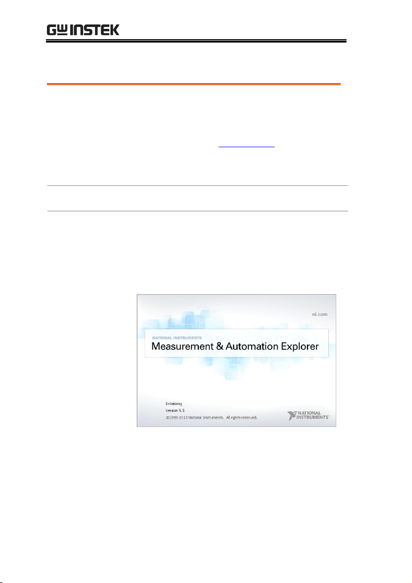
Functionality
Check
Please use the National Instruments
Measurement & Automation Controller
software to confirm GPIB/LAN functionality.
See the National Instrument website,
http://www.ni.com for details.
Note
For further details, please see the programming
manual, available on the GW Instek web site @
www.gwinstek.com
Operating System: Windows XP, 7, 8, 10
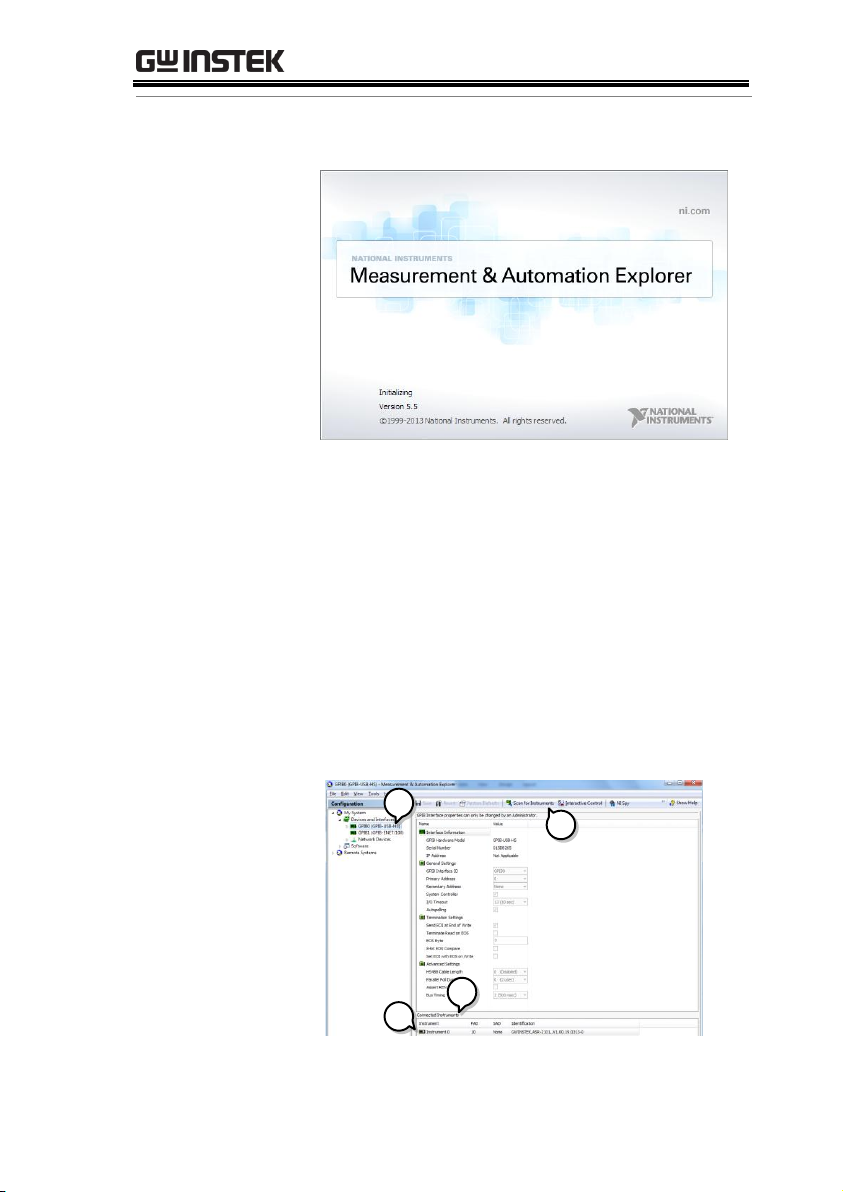
Operation
1. Start the NI Measurement and
Automation Explorer (MAX)
program. Using Windows, press:
GPIB Function Check
32
Page 33
REMOTE CONTROL
Start>All Programs>NI MAX
2. From the Configuration panel access;
My System>Devices and Interfaces>GPIB0
3. Press the Scan for Instruments button.
4. In the Connected Instruments panel the ASR-3000
should be detected as Instrument 0 with the
address the same as that configured on the
ASR-3000.
5. Double click the Instrument 0 icon.
2
4
3
5
33
Page 34
ASR-3000 Programming Manual
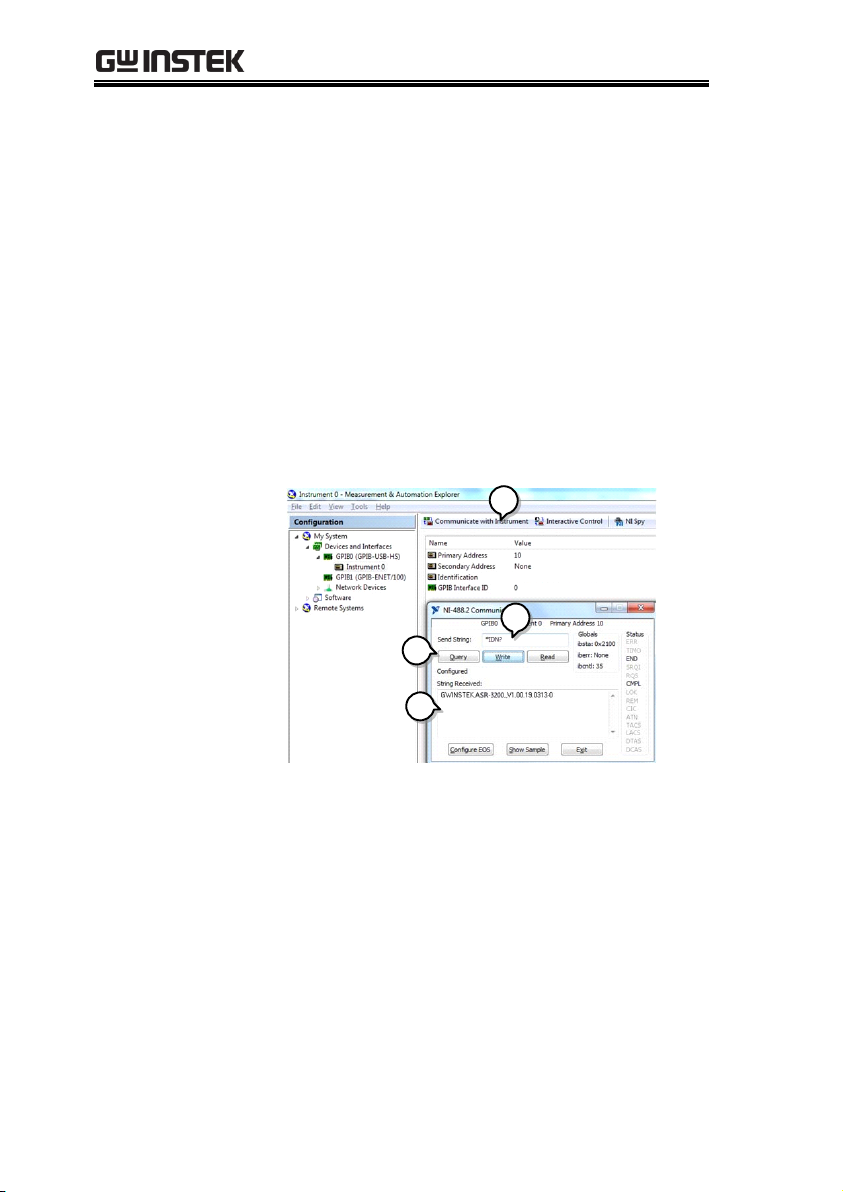
6. Click on Communicate with Instrument.
7. Under the Communicator tab, ensure *IDN? is
written in the Send String text box.
8. Click on the Query button to send the *IDN?
query to the instrument.
9. The instrument identification string will be
returned to the buffer area:
GW-INSTEK,ASR-XXXX,GXXXXXXXX,XX.XX
(manufacturer, model, serial number, software
version)
9
6
7
8
GW-INSTEK,ASR-XXXX,GXXXXXXXX,XX.XX
10. The function check is complete.
34
Page 35
REMOTE CONTROL
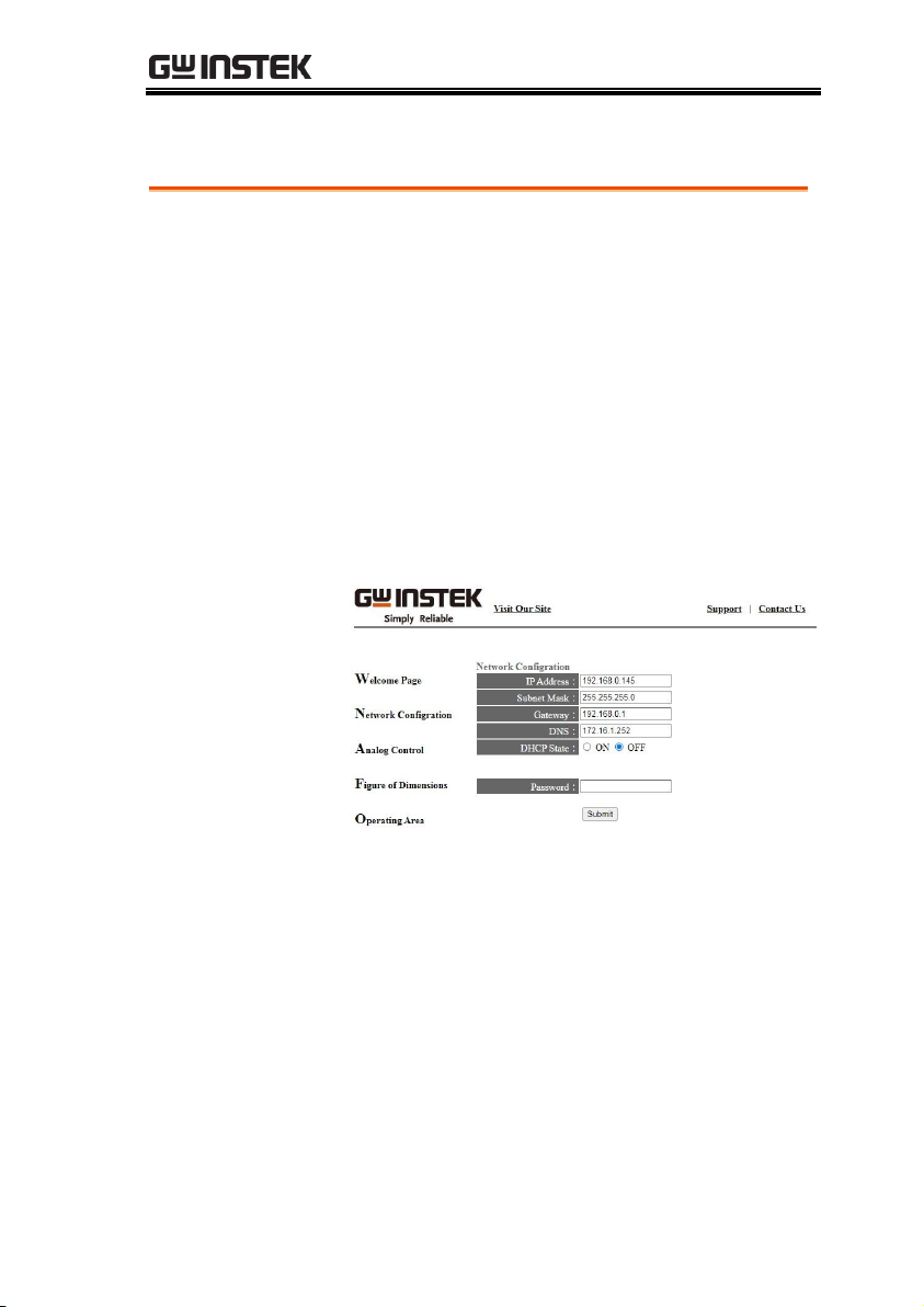
Functionality
Check
Enter the IP address of the power supply (for
example: http:// XXX.XXX.XXX.XXX) in a web
browser after the instrument has been
configured for LAN (page 21).
The web interface allows you to:
View the system and information and the network
configuration.
View the analog control pinout.
View the dimensions of the unit.
View the operating area
Example:
Web Server Remote Control Function Check
35
Page 36
ASR-3000 Programming Manual
Background
To test the socket server functionality, National
Instruments Measurement and Automation
Explorer can be used. This program is available
on the NI website, www.ni.com., via a search
for the VISA Run-time Engine page, or
“downloads” at the following URL,
http://www.ni.com/visa/
Requirements
Operating System: Windows XP, 7, 8, 10
Functionality
Check
1. Start the NI Measurement and Automation
Explorer (MAX) program. Using Windows,
press:
Start>All Programs>NI MAX
2. From the Configuration panel access;
My System>Devices and Interfaces>Network
Devices
3. Press Add New Network Device>Visa TCP/IP
Resource…
Socket Server Function Check
36
Page 37

REMOTE CONTROL
2
3
4. Select Manual Entry of Raw Socket from the
popup window.
4
5. Enter the IP address and the port number of the
ASR-3000. The port number is fixed at 2268.
6. Double click the Validate button and press
Next.
37
Page 38

ASR-3000 Programming Manual
5
6
7. Next configure the Alias (name) of the ASR-
3000 connection. In this example the Alias is:
ASR
8. Click finish.
7
8
9. The IP address of the power supply will now
appear under Network Devices in the
configuration panel. Select this icon now.
10. Press Open VISA Test Panel.
38
Page 39

REMOTE CONTROL
9
10
11. Click the Configuration Icon. Under the IO
Settings tab check Enable Termination Character.
The termination character should be set as Line
Feed -\n.
11
12. Click the Input/Output icon. Under the Basic I/O
tab, make sure *IDN?\n is entered in the Select
or Enter Command drop box.
13. Click Query.
The ASR-3000 will return the machine
identification string into the buffer area:
GW-INSTEK,ASR-XXXX,GXXXXXXXX,XX.XX
39
Page 40

ASR-3000 Programming Manual
13
12
GW-INSTEK,ASR-XXXX,GXXXXXXXX,XX.XX
Note
For further details, please see the programming
manual, available on the GW Instek web site @
www.gwinstek.com.
40
Page 41

REMOTE CONTROL
Compatible
Standard
IEEE488.2
Partial compatibility
SCPI, 1999
Partial compatibility
Command
Structure
SCPI commands follow a tree-like structure,
organized into nodes. Each level of the
command tree is a node. Each keyword in a
SCPI command represents each node in the
command tree. Each keyword (node) of a SCPI
command is separated by a colon (:).
For example, the diagram below shows an SCPI
sub-structure and a command example.
RMS
MEASure
SCALar
VOLTage
FREQuency
CURRent
RMS
MEASure:SCALar:FREQuency?
Command types
There are a number of different instrument
commands and queries. A command sends
instructions or data to the unit and a query
receives data or status information from the
unit.
Command types
Simple
A single command
with/without a parameter
Example
*IDN?
Command Syntax
41
Page 42

ASR-3000 Programming Manual
Query
A query is a simple or
compound command
followed by a question mark
(?). A parameter (data) is
returned.
Example
meas:curr?
Compound
Two or more commands on
the same command line.
Compound commands are
separated with either a semicolon (;) or a semi-colon and a
colon (;:).
A semi-colon is used to join
two related commands, with
the caveat that the last
command must begin at the
last node of the first
command.
Example
meas:volt?;curr?
A semi-colon and colon are
used to combine two
commands from different
nodes.
Example
meas:volt?;:sour:volt?
Note
(Further
explanation)
A semi-colon(;) is used to connect two commands.
A colon(:) at the start of a command indicates that
the command starts from the root node. The first
command can ignore that first colon. Any
commands after the first command (for compound
commands) that do not begin with a colon, must
begin at the last node of the first command.
42
Page 43

REMOTE CONTROL
Command Forms
Commands and queries have two different
forms, long and short. The command syntax is
written with the short form of the command in
capitals and the remainder (long form) in lower
case.
The commands can be written in capitals or
lower-case, just so long as the short or long
forms are complete. An incomplete command
will not be recognized.
Below are examples of correctly written
commands.
Long
form
:SYSTem:ERRor?
:SYSTEM:ERROR?
:system:error?
Short
form
SYST:ERR?
syst:err?
Square Brackets
Commands that contain square brackets
indicate that the contents are optional. The
function of the command is the same with or
without the square bracketed items, as shown
below.
For example the query “:OUTPut[:STATe]?”
has two valid forms, “:OUTPut:STATe?” and
“:OUTPut?”.
Command
Format
P1,P2
1 2 3 4 5
HEADER
1. Command header
2. Space
3. Parameter 1
4. Comma (no space
before/after comma)
5. Parameter 2
43
Page 44

ASR-3000 Programming Manual
Parameters
Type
Description
Example
<Boolean>
Boolean logic
0, 1
<NR1>
integers
0, 1, 2, 3
<NR2>
decimal
numbers
0.1, 3.14, 8.5
<NR3>
floating point
4.5e-1, 8.25e+1
<NRf>
any of NR1, 2, 3
1, 1.5, 4.5e-1
<block data>
Definitive length arbitrary block
data. A single decimal digit
followed by data. The decimal
digit specifies how many 8-bit
data bytes follow.
Message
Terminator
LF
Line feed code
44
Page 45

REMOTE CONTROL
Common
Commands
*CLS .......................................................................... 51
*ESE .......................................................................... 51
*ESR .......................................................................... 52
*IDN ......................................................................... 52
*OPC ......................................................................... 52
*RCL ......................................................................... 53
*RST .......................................................................... 53
*SAV ......................................................................... 53
*SRE .......................................................................... 54
*STB .......................................................................... 54
*WAI ......................................................................... 54
Data/Trace
Commands
:DATA|TRACe:SEQuence:CLEar........................ 55
:DATA|TRACe:SEQuence:RECall....................... 55
:DATA|TRACe:SEQuence:STORe....................... 56
:DATA|TRACe:SIMulation:CLEar ...................... 56
:DATA|TRACe:SIMulation:RECall ..................... 56
:DATA|TRACe:SIMulation:STORe ..................... 57
:DATA|TRACe:WAVe:CLEar .............................. 57
:DATA|TRACe:WAVe[:DATA]........................... 58
Measure
Commands
:MEASure[:SCALar]:CURRent:CFACtor ............ 60
:MEASure[:SCALar]:CURRent:HIGH ................. 60
:MEASure[:SCALar]:CURRent:LOW ................... 60
:MEASure[:SCALar]:CURRent:PEAK:CLEar ..... 60
:MEASure[:SCALar]:CURRent:PEAK:HOLD .... 60
:MEASure[:SCALar]:CURRent[:RMS] ................. 61
:MEASure[:SCALar]:CURRent:AVERage ........... 61
:MEASure[:SCALar]:CURRent:HARMonic[
:RMS] ........................................................................ 61
:MEASure[:SCALar]:CURRent:HARMonic
:RATio ...................................................................... 61
:MEASure[:SCALar]:FREQuency ......................... 62
:MEASure[:SCALar]:POWer[:AC]:APParent ..... 62
Command List
45
Page 46

ASR-3000 Programming Manual
:MEASure[:SCALar]:POWer[:AC]:PFACtor ....... 62
:MEASure[:SCALar]:POWer[:AC]:REACtive ..... 62
:MEASure[:SCALar]:POWer[:AC][:REAL] ......... 62
:MEASure[:SCALar]:VOLTage[:RMS] ................. 63
:MEASure[:SCALar]:VOLTage:AVERage ........... 63
:MEASure[:SCALar]:VOLTage:HIGH ................. 63
:MEASure[:SCALar]:VOLTage:LOW .................. 63
:MEASure[:SCALar]:VOLTage:HARMonic[
:RMS] ........................................................................ 64
:MEASure[:SCALar]:VOLTage:HARMonic
:RATio ...................................................................... 64
:MEASure:CONFigure:SENSing .......................... 64
Memory
Commands
:MEMory:RCL ......................................................... 65
:MEMory:SAV ......................................................... 65
Output
Commands
:OUTPut[:STATe] ................................................... 66
:OUTPut:PON ......................................................... 66
:OUTPut:PROTection:CLEar ................................ 67
:OUTPut:RELay ...................................................... 67
Status
Commands
:STATus:OPERation:CONDition.......................... 68
:STATus:OPERation:ENABle ................................ 68
:STATus:OPERation[:EVENt] ............................... 69
:STATus:OPERation:NTRansition ....................... 69
:STATus:OPERation:PTRansition ........................ 69
:STATus:QUEStionable[:EVENt] .......................... 70
:STATus:QUEStionable:CONDition .................... 70
:STATus:QUEStionable:ENABle .......................... 70
:STATus:QUEStionable:NTRansition .................. 70
:STATus:QUEStionable:PTRansition ................... 71
:STATus:PRESet ...................................................... 71
:STATus:WARNing:CONDition .......................... 72
:STATus:WARNing:ENABle ................................ 72
:STATus:WARNing[:EVENt] ................................ 72
:STATus:WARNing:NTRansition ........................ 73
:STATus:WARNing:PTRansition ......................... 73
46
Page 47

REMOTE CONTROL
:STATus:LOCK:CONDition .................................. 73
:STATus:LOCK:ENABle ........................................ 73
:STATus:LOCK[:EVENt] ....................................... 74
:STATus:LOCK:NTRansition ................................ 74
:STATus:LOCK:PTRansition ................................. 74
System
Commands
:SYSTem:ARBitrary:EDIT:BUILtin ....................... 76
:SYSTem:ARBitrary:EDIT:SURGe ........................ 76
:SYSTem:ARBitrary:EDIT:STAir .......................... 77
:SYSTem:ARBitrary:EDIT:CFACtor2 ................... 77
:SYSTem:ARBitrary:EDIT:CFACtor1 ................... 78
:SYSTem:ARBitrary:EDIT:CLIP ............................ 78
:SYSTem:ARBitrary:EDIT:STORe ......................... 79
:SYSTem:ARBitrary:EDIT:TRIangle ..................... 80
:SYSTem:BEEPer:STATe ........................................ 80
:SYSTem:COMMunicate:GPIB[:SELF]
:ADDRess ................................................................ 81
:SYSTem:COMMunicate:LAN:DHCP ................. 81
:SYSTem:COMMunicate:LAN:DNS .................... 81
:SYSTem:COMMunicate:LAN:GATeway ........... 82
:SYSTem:COMMunicate:LAN:IPADdress .......... 82
:SYSTem:COMMunicate:LAN:MAC ................... 82
:SYSTem:COMMunicate:LAN:SMASk ................ 83
:SYSTem:COMMunicate:RLSTate ........................ 83
:SYSTem:COMMunicate:SERial[:RECeive]
:TRANsmit:BAUD .................................................. 84
:SYSTem:COMMunicate:SERial[:RECeive]
:TRANsmit:BITS ..................................................... 84
:SYSTem:COMMunicate:SERial[:RECeive]
:TRANsmit:PARity ................................................. 85
:SYSTem:COMMunicate:SERial[:RECeive]
:TRANsmit:SBITs.................................................... 86
:SYSTem:COMMunicate:TCPip:CONTrol .......... 86
:SYSTem:COMMunicate:USB:FRONt:STATe ..... 86
:SYSTem:COMMunicate:USB:REAR:STATe ...... 87
:SYSTem:CONFigure[:MODE] ............................. 87
:SYSTem:CONFigure:EXTio[:STATe] .................. 87
:SYSTem:ERRor ...................................................... 88
:SYSTem:ERRor:ENABle ....................................... 88
47
Page 48

ASR-3000 Programming Manual
:SYSTem:HOLD:STATe ......................................... 88
:SYSTem:IPKHold:TIME ....................................... 88
:SYSTem:KLOCk .................................................... 89
:SYSTem:REBoot ..................................................... 89
:SYSTem:SLEW:MODE .......................................... 89
:SYSTem:VUNit ...................................................... 90
Source
Commands
[:SOURce]:CURRent:LIMit:PEAK:HIGH ............ 91
[:SOURce]:CURRent:LIMit:PEAK:LOW ............. 92
[:SOURce]:CURRent:LIMit:RMS[:AMPLitude] .. 92
[:SOURce]:CURRent:LIMit:PEAK:MODE .......... 93
[:SOURce]:CURRent:LIMit:RMS:MODE ............. 93
[:SOURce]:FREQuency:LIMit:HIGH ................... 94
[:SOURce]:FREQuency:LIMit:LOW ..................... 94
[:SOURce]:FREQuency[:IMMediate] ................... 95
[:SOURce]:FUNCtion[:SHAPe][:IMMediate] ..... 95
[:SOURce]:FUNCtion:THD:FORMat ................... 96
[:SOURce]:MODE ................................................... 96
[:SOURce]:PHASe:STARt:STATe ......................... 97
[:SOURce]:PHASe:STOP:STATe........................... 98
[:SOURce]:PHASe:STARt[:IMMediate] ............... 98
[:SOURce]:PHASe:STOP[:IMMediate] ................ 99
[:SOURce]:READ .................................................... 99
[:SOURce]:VOLTage:RANGe ............................. 100
[:SOURce]:VOLTage:LIMit:RMS ........................ 100
[:SOURce]:VOLTage:LIMit:PEAK ...................... 101
[:SOURce]:VOLTage:LIMit:HIGH ..................... 101
[:SOURce]:VOLTage:LIMit:LOW ....................... 102
[:SOURce]:VOLTage[:LEVel][:IMMediate]
[:AMPLitude] ........................................................ 102
[:SOURce]:VOLTage[:LEVel][:IMMediate]
:OFFSet ................................................................... 103
Sequence
Commands
[:SOURce]:SEQuence:CPARameter ................... 104
[:SOURce]:SEQuence:CSTep ............................... 105
[:SOURce]:SEQuence:SPARameter .................... 105
[:SOURce]:SEQuence:STEP ................................. 106
[:SOURce]:SEQuence:CONDition ...................... 107
48
Page 49

REMOTE CONTROL
:TRIGger:SEQuence:SELected:EXECute ........... 107
Simulate
Commands
[:SOURce]:SIMulation:CONDition .................... 109
[:SOURce]:SIMulation:ABNormal:CODE ......... 109
[:SOURce]:SIMulation:ABNormal:FREQuency 110
[:SOURce]:SIMulation:ABNormal:PHASe
:STARt:ENABle ..................................................... 110
[:SOURce]:SIMulation:ABNormal:PHASe
:STARt[:IMMediate] ............................................. 111
[:SOURce]:SIMulation:ABNormal:PHASe
:STOP:ENABle ...................................................... 111
[:SOURce]:SIMulation:ABNormal:PHASe
:STOP[:IMMediate] .............................................. 112
[:SOURce]:SIMulation:ABNormal:TIME ........... 112
[:SOURce]:SIMulation:ABNormal:VOLTage .... 113
[:SOURce]:SIMulation:CSTep ............................. 113
[:SOURce]:SIMulation:INITial:CODE ................ 114
[:SOURce]:SIMulation:INITial:FREQuency ...... 114
[:SOURce]:SIMulation:INITial:PHASe:STARt
:ENABle ................................................................. 115
[:SOURce]:SIMulation:INITial:PHASe:STARt[
:IMMediate] ........................................................... 115
[:SOURce]:SIMulation:INITial:PHASe:STOP
:ENABle ................................................................. 116
[:SOURce]:SIMulation:INITial:PHASe:STOP[
:IMMediate] ........................................................... 116
[:SOURce]:SIMulation:INITial:VOLTage .......... 117
[:SOURce]:SIMulation:NORMal<1|2>:CODE . 117
[:SOURce]:SIMulation:NORMal 1:FREQuency 118
[:SOURce]:SIMulation:NORMal<1|2>
:PHASe:STARt:ENABle ....................................... 118
[:SOURce]:SIMulation:NORMal<1|2>
:PHASe:STARt[:IMMediate] ............................... 119
[:SOURce]:SIMulation:NORMal<1|2>
:PHASe:STOP:ENABle......................................... 119
[:SOURce]:SIMulation:NORMal<1|2>
:PHASe:STOP[:IMMediate] ................................. 120
[:SOURce]:SIMulation:NORMal<1|2>:TIME ... 120
[:SOURce]:SIMulation:NORMal 1:VOLTage .... 121
[:SOURce]:SIMulation:REPeat:COUNt ............. 121
49
Page 50

ASR-3000 Programming Manual
[:SOURce]:SIMulation:REPeat:ENABle ............. 122
[:SOURce]:SIMulation:TRANsition<1|2>:TIME122
[:SOURce]:SIMulation:TRANsition<1|2>
:CODE .................................................................... 123
:TRIGger:SIMulation:SELected:EXECute .......... 123
Input Commands
:INPut:GAIN ......................................................... 124
:INPut:SYNC:SOURce ......................................... 124
Display
Commands
:DISPlay[:WINDow]:DESign:MODE ................. 125
:DISPlay[:WINDow]:MEASure
:SOURce<1|2|3> ................................................. 125
50
Page 51

REMOTE CONTROL
*CLS .......................................................................... 51
*ESE .......................................................................... 51
*ESR .......................................................................... 52
*IDN ......................................................................... 52
*OPC ......................................................................... 52
*RCL ......................................................................... 53
*RST .......................................................................... 53
*SAV ......................................................................... 53
*SRE .......................................................................... 54
*STB .......................................................................... 54
*WAI ......................................................................... 54
*CLS
Set
Description
The *CLS command clears all the event registers,
including the status byte, event status and error
queue.
Syntax
*CLS
*ESE
Set
Query
Description
Sets or queries the Standard Event Status Enable
register.
Syntax
Query Syntax
*ESE <NR1>
*ESE?
Parameter
<NR1>
0~255
Return parameter
<NR1>
Returns the bit sum of the Standard Event
Status Enable register.
Common Commands
51
Page 52

ASR-3000 Programming Manual
*ESR
Query
Description
Queries the Standard Event Status (Event) register.
The Event Status register is cleared after it is read.
Query Syntax
*ESR?
Return parameter
<NR1>
Returns the bit sum of the Standard Event
Status (Event) register and clears the register.
*IDN
Query
Description
Queries the manufacturer, model name, serial
number, and firmware version of the ASR.
Query Syntax
*IDN?
Return parameter
<string>
Returns the instrument identification as a
string in the following format:
GW-INSTEK,ASR-XXXX,GXXXXXXXX,XX.XX
Manufacturer: GW-INSTEK
Model number : ASR-XXXX
Serial number : GXXXXXXXX
Firmware version : XX.XX
*OPC
Set
Query
Description
The *OPC? Query returns 1 when all the
outstanding commands have completed.
Query Syntax
*OPC?
Return parameter
1
Returns 1 when all the outstanding
commands have completed.
52
Page 53

REMOTE CONTROL
*RCL
Set
Description
Recalls the contents stored in memory slot M0 ~
M9. These memory slots are mapped to the preset
settings.
Syntax
*RCL {<NR1>|MINimum|MAXimum}
Parameter
<NR1>
0 ~ 9 (as memory M0 ~ M9)
MIN
Recalls the M0 memory contents.
MAX
Recalls the M9 memory contents.
*RST
Set
Description
Performs a device reset. Configures the unit to a
known configuration (default settings). This
known configuration is independent of the usage
history.
Syntax
*RST
*SAV
Set
Description
Saves the settings into memory slot M0 ~ M9.
These memory slots are mapped to the preset
settings.
Syntax
*SAV {<NR1>|MINimum|MAXimum}
Return parameter
<NR1>
0 ~ 9 (as memory M0 ~ M9)
MIN
Saves to the M0 memory slot.
MAX
Saves to the M9 memory slot.
53
Page 54

ASR-3000 Programming Manual
*SRE
Set
Query
Description
Sets or queries the Service Request Enable register.
The Service Request Enable register determines
which registers of the Status Byte register are able
to generate service requests.
Syntax
Query Syntax
*SRE <NR1>
*SRE?
Parameter
<NR1>
0~255
Return parameter
<NR1>
Returns the bit sum of the Service Request
Enable register.
*STB
Query
Description
Queries the bit sum of the Status Byte register with
MSS (Master summary Status) replacing the RQS
bit (bit 6).
Query Syntax
*STB?
Return parameter
<NR1>
Returns the bit sum of the Status Byte register
with the MSS bit (bit 6).
*WAI
Set
Description
Prevents any other commands or queries from
being executed until all outstanding commands
have completed.
Syntax
*WAI
54
Page 55

REMOTE CONTROL
Note
The TRACE and DATA node for the following
commands are functionally equivalent.
:DATA|TRACe:SEQuence:CLEar........................ 55
:DATA|TRACe:SEQuence:RECall....................... 55
:DATA|TRACe:SEQuence:STORe....................... 56
:DATA|TRACe:SIMulation:CLEar ...................... 56
:DATA|TRACe:SIMulation:RECall ..................... 56
:DATA|TRACe:SIMulation:STORe ..................... 57
:DATA|TRACe:WAVe:CLEar .............................. 57
:DATA|TRACe:WAVe[:DATA]........................... 58
:DATA|TRACe:SEQuence:CLEar
Set
Description
Clears the sequence data for the selected save
memory (Seq0 ~ Seq9).
Syntax
:DATA|TRACe:SEQuence:CLEar
{<NR1>|MINimum|MAXimum}
Parameter
<NR1>
0~9
MIN
0
MAX
9
Example
:DATA:SEQ:CLE 1
Clears the sequence data from Seq1.
:DATA|TRACe:SEQuence:RECall
Set
Description
Loads the sequence data. This command is the
equivalent to recalling a sequence memory in the
Sequence mode.
Syntax
:DATA|TRACe:SEQuence:RECall
{<NR1>|MINimum|MAXimum}
Parameter
<NR1>
0~9 (Seq0 ~ Seq9).
MIN
0
Trace/Data Commands
55
Page 56

ASR-3000 Programming Manual
MAX
9
Example
:DATA:SEQ:REC 1
Loads the data from Seq1.
:DATA|TRACe:SEQuence:STORe
Set
Description
Saves the sequence data. This command is the
equivalent to saving a sequence memory in
Sequence mode.
Syntax
:DATA|TRACe:SEQuence:STORe
{<NR1>|MINimum|MAXimum}
Parameter
<NR1>
0~9 (Seq0 ~ Seq9).
MIN
0
MAX
9
Example
:DATA:SEQ:STOR 1
Saves the data from Seq1.
:DATA|TRACe:SIMulation:CLEar
Set
Description
Clears the simulation data for the selected save
memory (SIM0 ~ SIM9).
Syntax
:DATA|TRACe:SIMulation:CLEar
{<NR1>|MINimum|MAXimum}
Parameter
<NR1>
0~9 (SIM0 ~ SIM9).
MIN
0
MAX
9
Example
:DATA:SIM:CLE 1
Clears the simulation data from SIM1.
:DATA|TRACe:SIMulation:RECall
Set
Description
Loads the simulation data. This command is the
equivalent to recalling a simulation memory in the
Simulation mode (SIM0~SIM9).
56
Page 57

REMOTE CONTROL
Syntax
:DATA|TRACe:SIMulation:RECall
{<NR1>|MINimum|MAXimum}
Parameter
<NR1>
0~9 (SIM0 ~ SIM9).
MIN
0
MAX
9
Example
:DATA:SIM:REC 1
Loads the data from SIM1.
:DATA|TRACe:SIMulation:STORe
Set
Description
Saves the simulation data. This command is the
equivalent saving a simulation memory in
Simulation mode (SIM0 ~ SIM9).
Syntax
:DATA|TRACe:SIMulation:STORe
{<NR1>|MINimum|MAXimum}
Parameter
<NR1>
0~9 (SIM0 ~ SIM9).
MIN
0
MAX
9
Example
:DATA:SIM:STOR 1
Saves the data from SIM1.
:DATA|TRACe:WAVe:CLEar
Set
Description
Clears the ARB 1-16 data for the selected wave
group.
Syntax
:DATA|TRACe:WAVe:CLEar
{<NR1>|MINimum|MAXimum}
Parameter
<NR1>
1~16 (ARB1 ~ ARB16).
MIN
1 (ARB1)
MAX
16 (ARB16)
Example
:DATA:WAV:CLE 13
Clears the wave data from ARB13.
57
Page 58

ASR-3000 Programming Manual
:DATA|TRACe:WAVe[:DATA]
Set
Description
Sets the arbitrary wave.
Syntax
:DATA|TRACe:WAVe[:DATA] {<NR1>|<Binary Data>}
Parameter
<NR1>
1 – 16 (ARB 1 – 16)
Binary Data includes the #48192<DAB>...<DAB>
#
Indicates the block data is sent.
4
Indicates the number of subsequent numbers.
8192
Indicates the number of subsequent byte data.
<DAB>..
.<DAB>
Indicates 16-bit with 4096 words waveform
data. Plus, the data format of wave is the big
endian in the form of two’s complement.
Example
TRAC:WAV 1, #48192<DAB>...<DAB>
58
Page 59

REMOTE CONTROL
:MEASure[:SCALar]:CURRent:CFACtor ............ 60
:MEASure[:SCALar]:CURRent:HIGH ................. 60
:MEASure[:SCALar]:CURRent:LOW ................... 60
:MEASure[:SCALar]:CURRent:PEAK:CLEar ..... 60
:MEASure[:SCALar]:CURRent:PEAK:HOLD .... 60
:MEASure[:SCALar]:CURRent[:RMS] ................. 61
:MEASure[:SCALar]:CURRent:AVERage ........... 61
:MEASure[:SCALar]:CURRent:HARMonic[
:RMS] ........................................................................ 61
:MEASure[:SCALar]:CURRent:HARMonic
:RATio ...................................................................... 61
:MEASure[:SCALar]:FREQuency ......................... 62
:MEASure[:SCALar]:POWer[:AC]:APParent ..... 62
:MEASure[:SCALar]:POWer[:AC]:PFACtor ....... 62
:MEASure[:SCALar]:POWer[:AC]:REACtive ..... 62
:MEASure[:SCALar]:POWer[:AC][:REAL] ......... 62
:MEASure[:SCALar]:VOLTage[:RMS] ................. 63
:MEASure[:SCALar]:VOLTage:AVERage ........... 63
:MEASure[:SCALar]:VOLTage:HIGH ................. 63
:MEASure[:SCALar]:VOLTage:LOW .................. 63
:MEASure[:SCALar]:VOLTage:HARMonic[
:RMS] ........................................................................ 64
:MEASure[:SCALar]:VOLTage:HARMonic
:RATio ...................................................................... 64
:MEASure:CONFigure:SENSing .......................... 64
Measure Commands
59
Page 60
ASR-3000 Programming Manual
:MEASure[:SCALar]:CURRent:CFACtor
Query
Description
Returns the output current crest factor (CF).
Query syntax
:MEASure[:SCALar]:CURRent:CFACtor?
Return parameter
<NR2>
Returns the crest factor.
:MEASure[:SCALar]:CURRent:HIGH
Query
Description
Returns the output current maximum peak value
(Imax).
Note:
Current maximum peak value is defined as the
highest peak value in the complete period.
Query syntax
:MEASure[:SCALar]:CURRent:HIGH?
Return parameter
<NR2>
Returns the Imax value in amps.
:MEASure[:SCALar]:CURRent:LOW
Query
Description
Returns the output current minimum value (Imin).
Note:
Current minimum value is defined as the lowest
value in the complete period.
Query syntax
:MEASure[:SCALar]:CURRent:LOW?
Return parameter
<NR2>
Returns the Imin value in amps.
:MEASure[:SCALar]:CURRent:PEAK:CLEar
Set
Description
Clears the current peak-hold value.
Syntax
:MEASure[:SCALar]:CURRent:PEAK:CLEar
:MEASure[:SCALar]:CURRent:PEAK:HOLD
Query
Description
Returns the current peak hold value in amps (IPK
Hold).
Query syntax
:MEASure[:SCALar]:CURRent:PEAK:HOLD?
60
Page 61
REMOTE CONTROL
Return
<NR2>
Returns the peak hold value in amps.
:MEASure[:SCALar]:CURRent[:RMS]
Query
Description
Returns the output current (Irms).
Query syntax
:MEASure[:SCALar]:CURRent[:RMS]?
Return
<NR2>
Returns the current value in Irms.
:MEASure[:SCALar]:CURRent:AVERage
Query
Description
Returns the current average value (Iavg).
Query syntax
:MEASure[:SCALar]:CURRent:AVERage?
Return
<NR2>
Returns the current average value in amps.
:MEASure[:SCALar]:CURRent:HARMonic[:RMS]
Query
Description
Returns 41 values covering Total and order 1 to 40
current (Irms) in harmonic. (Only AC-INT and 50
/60 Hz Active)
Query syntax
:MEASure[:SCALar]:CURRent:HARMonic[:RMS]?
Return
<NR2>,<NR2
>,<NR2>,
<NR2>…, etc.
Returns the entire 41 values
containing Total and order 1 to 40
current (Irms) in harmonic.
:MEASure[:SCALar]:CURRent:HARMonic:RATio
Query
Description
Returns 41 values covering Total and order 1 to 40
current (Ratio) in harmonic. (Only AC-INT and 50
/60 Hz Active)
Query syntax
:MEASure[:SCALar]:CURRent:HARMonic:RATio?
Return
<NR2>,<NR2
>,<NR2>,
<NR2>…, etc.
Returns the entire 41 values
containing Total and order 1 to 40
current (Ratio) in harmonic.
61
Page 62

ASR-3000 Programming Manual
:MEASure[:SCALar]:FREQuency
Query
Description
Returns the SYNC signal source frequency in Hz.
(Only AC+DC-sync or AC-sync Active)
Query syntax
:MEASure[:SCALar]:FREQuency?
Return
<NR2>
Returns the SYNC frequency in Hz.
:MEASure[:SCALar]:POWer[:AC]:APParent
Query
Description
Returns the apparent power (S).
Query syntax
:MEASure[:SCALar]:POWer[:AC]:APParent?
Return
<NR2>
Returns the apparent power in VA.
:MEASure[:SCALar]:POWer[:AC]:PFACtor
Query
Description
Returns the power factor (PF).
Query syntax
:MEASure[:SCALar]:POWer[:AC]:PFACtor?
Return
<NR2>
Returns the power factor.
:MEASure[:SCALar]:POWer[:AC]:REACtive
Query
Description
Returns the reactive power (Q).
Query syntax
:MEASure[:SCALar]:POWer[:AC]:REACtive?
Return
<NR2>
Returns the reactive power in VAR.
:MEASure[:SCALar]:POWer[:AC][:REAL]
Query
Description
Returns the active power in Watts (P).
Query syntax
:MEASure[:SCALar]:POWer[:AC][:REAL]?
Return
<NR2>
Returns the power in Watts.
62
Page 63

REMOTE CONTROL
:MEASure[:SCALar]:VOLTage[:RMS]
Query
Description
Returns the voltage (Vrms).
Query syntax
:MEASure[:SCALar]:VOLTage[:RMS]?
Return
<NR2>
Returns the voltage value in Vrms.
:MEASure[:SCALar]:VOLTage:AVERage
Query
Description
Returns the voltage average value (Vavg).
Query syntax
:MEASure[:SCALar]:VOLTage:AVERage?
Return
<NR2>
Returns the voltage average value in volts.
:MEASure[:SCALar]:VOLTage:HIGH
Query
Description
Returns the output voltage maximum peak value
(Vmax).
Note:
Voltage maximum peak value is defined as the
highest peak value in the complete period.
Query syntax
:MEASure[:SCALar]:VOLTage:HIGH?
Return parameter
<NR2>
Returns the Vmax value in volts.
:MEASure[:SCALar]:VOLTage:LOW
Query
Description
Returns the output current minimum value (Vmin).
Note:
Voltage minimum value is defined as the lowest
value in the complete period.
Query syntax
:MEASure[:SCALar]:VOLTage:LOW?
Return parameter
<NR2>
Returns the Vmin value in volts.
63
Page 64
ASR-3000 Programming Manual
:MEASure[:SCALar]: VOLTage:HARMonic[:RMS]
Query
Description
Returns 41 values covering Total and order 1 to 40
voltage (Vrms) in harmonic. (Only AC-INT and 50
/60 Hz Active)
Query syntax
:MEASure[:SCALar]: VOLTage:HARMonic[:RMS]?
Return
<NR2>,<NR2
>,<NR2>,
<NR2>…, etc.
Returns the entire 41 values
containing Total and order 1 to 40
voltage (Vrms) in harmonic.
:MEASure[:SCALar]: VOLTage:HARMonic:RATio
Query
Description
Returns 41 values covering Total and order 1 to 40
voltage (Ratio) in harmonic. (Only AC-INT and 50
/60 Hz Active)
Query syntax
:MEASure[:SCALar]: VOLTage:HARMonic:RATio?
Return
<NR2>,<NR2
>,<NR2>,
<NR2>…, etc.
Returns the entire 41 values
containing Total and order 1 to 40
voltage (Ratio) in harmonic.
:MEASure:CONFigure:SENSing
Set
Query
Description
Sets or queries the remote sense configuration.
(Only AC-INT, DC-INT, AC-SYNC Mode and
100V, 200V Range and SIN Wave Shape and Time
Slew Rate Mode Active)
Syntax
Query Syntax
:MEASure:CONFigure:SENSing {<bool>|OFF|ON}
:MEASure:CONFigure:SENSing?
Parameter
OFF | 0
Turns the remote sense off.
ON | 1
Turns the remote sense on.
Return parameter
<bool>
Returns the status of remote sense.
Example
:MEAS:CONF:SENS 0
Sets the remote sense off.
64
Page 65

REMOTE CONTROL
:MEMory:RCL ......................................................... 65
:MEMory:SAV ......................................................... 65
:MEMory:RCL
Set
Description
Recalls the settings from memory slot M0~M9.
These memory slots are mapped to the preset
settings. Equivalent to the *RCL command.
Syntax
:MEMory:RCL {<NR1>|MINimum|MAXimum}
Parameter
<NR1>
0~9
MINimum
0
MAXimum
9
Example
:MEMory:RCL
Recall the settings from M1.
:MEMory:SAV
Set
Description
Saves the settings into memory slot M0 ~ M9.
These memory slots are mapped to the preset
settings. Equivalent to the *SAV command.
Syntax
:MEMory:SAV {<NR1>|MINimum|MAXimum}
Parameter
<NR1>
0~9
MINimum
0
MAXimum
9
Example
:MEMory:SAV 1
Save the settings to M1.
Memory Commands
65
Page 66

ASR-3000 Programming Manual
:OUTPut[:STATe] ................................................... 66
:OUTPut:PON ......................................................... 66
:OUTPut:PROTection:CLEar ................................ 67
:OUTPut:RELay ...................................................... 67
:OUTPut[:STATe]
Set
Query
Description
Sets or queries the output state of power source.
Syntax
Query Syntax
:OUTPut[:STATe] {<bool>|OFF|ON}
:OUTPut[:STATe]?
Parameter
OFF | 0
Turns the output off.
ON | 1
Turns the output on.
Return parameter
<bool>
Returns output status of the instrument.
Example
:OUTP 0
Sets power output off.
:OUTPut:PON
Set
Query
Description
Sets the output state at power-on.
Syntax
Return Syntax
:OUTPut:PON {<NR1>|OFF|ON|SEQ|SIM}
:OUTPut:PON?
Parameter
<NR1>
0 ~ 3
OFF| 0
Disabled
ON | 1
Enabled
SEQ | 2
Sequence function
SIM | 3
Simulate function
Return parameter
<NR1>
Returns the selected output state at poweron from 0 to 3.
Example
:OUTPut:PON 2
Sets sequence function on at power-on.
Output Commands
66
Page 67

REMOTE CONTROL
:OUTPut:PROTection:CLEar
Set
Description
The Command will clear alarms like Over Current,
Over Peak Current, Output Over-Power, Output
Short, Output Overvoltage, Sensing Voltage Error.
Syntax
:OUTPut:PROTection:CLEar
:OUTPut:RELay
Set
Query
Description
Sets or queries the output relay of power source.
Syntax
Query Syntax
:OUTPut:RELay {<bool>|OFF|ON}
:OUTPut:RELay?
Parameter
OFF | 0
Turns the output relay Disable.
ON | 1
Turns the output relay Enable.
Return parameter
<bool>
Returns output relay of the instrument.
Example
:OUTP:REL 1
Sets output relay Enable.
67
Page 68

ASR-3000 Programming Manual
:STATus:OPERation:CONDition ......................... 68
:STATus:OPERation:ENABle ................................ 68
:STATus:OPERation[:EVENt] ............................... 69
:STATus:OPERation:NTRansition ....................... 69
:STATus:OPERation:PTRansition ........................ 69
:STATus:QUEStionable[:EVENt].......................... 70
:STATus:QUEStionable:CONDition .................... 70
:STATus:QUEStionable:ENABle .......................... 70
:STATus:QUEStionable:NTRansition .................. 70
:STATus:QUEStionable:PTRansition ................... 71
:STATus:PRESet ...................................................... 71
:STATus:WARNing:CONDition .......................... 72
:STATus:WARNing:ENABle ................................ 72
:STATus:WARNing[:EVENt] ................................ 72
:STATus:WARNing:NTRansition ........................ 73
:STATus:WARNing:PTRansition ......................... 73
:STATus:LOCK:CONDition .................................. 73
:STATus:LOCK:ENABle ........................................ 73
:STATus:LOCK[:EVENt] ....................................... 74
:STATus:LOCK:NTRansition ................................ 74
:STATus:LOCK:PTRansition................................. 74
:STATus:OPERation:CONDition
Query
Description
Queries the Operation Status register. This query
will not clear the register.
Syntax
:STATus:OPERation:CONDition?
Return
<NR1>
Returns the bit sum of the Operation
Condition register. (0~32767)
:STATus:OPERation:ENABle
Set
Query
Description
Sets or queries the bit sum of the Operation Status
Enable register.
Status Commands
68
Page 69

REMOTE CONTROL
Syntax
Query Syntax
:STATus:OPERation:ENABle <NR1>
:STATus:OPERation:ENABle?
Parameter
<NR1>
0~32767
Return parameter
<NR1>
0~32767
:STATus:OPERation[:EVENt]
Query
Description
Queries the Operation Status Event register and
clears the contents of the register.
Syntax
:STATus:OPERation[:EVENt]?
Return
<NR1>
Returns the bit sum of the Operation Status
Event register.
:STATus:OPERation:NTRansition
Set
Query
Description
Sets or queries the bit sum of the negative
transition filter of the Operation Status register.
Syntax
Query Syntax
:STATus:OPERation:NTRansition <NR1>
:STATus:OPERation:NTRansition?
Parameter
<NR1>
0~32767
Return parameter
<NR1>
0~32767
:STATus:OPERation:PTRansition
Set
Query
Description
Sets or queries the bit sum of the positive
transition filter of the Operation Status register.
Syntax
:STATus:OPERation:PTRansition <NR1>
:STATus:OPERation:PTRansition?
Parameter
<NR1>
0~32767
Return parameter
<NR1>
0~32767
69
Page 70

ASR-3000 Programming Manual
:STATus:QUEStionable[:EVENt]
Query
Description
Queries the bit sum of the Questionable Status
Event register. This query will also clear the
contents of the register.
Query Syntax
:STATus:QUEStionable[:EVENt]?
Return parameter
<NR1>
0~32767
:STATus:QUEStionable:CONDition
Query
Description
Queries the status (bit sum) of the Questionable
Status register. This query will not clear the
register.
Query Syntax
:STATus:QUEStionable:CONDition?
Return parameter
<NR1>
0~32767
:STATus:QUEStionable:ENABle
Set
Query
Description
Sets or queries the bit sum of the Questionable
Status Enable register.
Syntax
Query Syntax
:STATus:QUEStionable:ENABle <NR1>
:STATus:QUEStionable:ENABle?
Parameter
<NR1>
0~32767
Return parameter
<NR1>
0~32767
:STATus:QUEStionable:NTRansition
Set
Query
Description
Sets or queries the bit sum of the negative
transition filter of the Questionable Status register.
Syntax
Query Syntax
:STATus:QUEStionable:NTRansition <NR1>
:STATus:QUEStionable:NTRansition?
Parameter
<NR1>
0~32767
Return parameter
<NR1>
0~32767
70
Page 71

:STATus:QUEStionable:PTRansition
Set
Query
Description
Sets or queries the bit sum of the positive
transition filter of the Questionable Status register.
Syntax
Return Syntax
:STATus:QUEStionable:PTRansition <NR1>
:STATus:QUEStionable:PTRansition?
Parameter
<NR1>
0~32767
Return parameter
<NR1>
0~32767
:STATus:PRESet
Set
Description
This command resets the ENABle register, the
PTRansistion filter and NTRansistion filter on the
Operation Status, Questionable Status, Warning
Status and System Lock Status Registers. The
registers/filters will be reset to a default value.
Default Register/Filter Values
Setting
QUEStionable Status Enable
0x0000
QUEStionable Status Positive Transition
0x7FFF
QUEStionable Status Negative Transition
0x0000
Operation Status Enable
0x0000
Operation Status Positive Transition
0x7FFF
Operation Status Negative Transition
0x0000
WARNing Status Enable
0x0000
WARNing Status Positive Transition
0x7FFF
WARNing Status Negative Transition
0x0000
System Lock Status Enable
0x0000
System Lock Status Positive Transition
0x7FFF
System Lock Status Negative Transition
0x0000
REMOTE CONTROL
71
Page 72

ASR-3000 Programming Manual
Summary: The Questionable Status Enable
registers, the Operation Status Enable registers,
Warning Status registers and System Lock Status
registers are both reset to 0.
The Questionable Status, Operation Status,
Warning Status and System Lock Status Positive
Transition filters are all set high (0x7FFF) and the
Negative Transition filters are all set low (0x0000).
I.e., only positive transitions will be recognized for
the Questionable Status, Operation Status,
Warning Status and System Lock Status registers.
Syntax
:STATus:PRESet
:STATus:WARNing:CONDition
Query
Description
Queries the Warning Status register. This query
will not clear the register.
Syntax
:STATus:WARNing:CONDition?
Return
<NR1>
Returns the bit sum of the Warning Condition
register. (0~32767)
:STATus:WARNing:ENABle
Set
Query
Description
Sets or queries the bit sum of the Warning Status
Enable register.
Syntax
Query Syntax
:STATus:WARNing:ENABle <NR1>
:STATus:WARNing:ENABle?
Parameter
<NR1>
0~32767
Return parameter
<NR1>
0~32767
:STATus:WARNing[:EVENt]
Query
Description
Queries the Warning Status Event register and
clears the contents of the register.
Syntax
:STATus:WARNing[:EVENt]?
72
Page 73
REMOTE CONTROL
Return
<NR1>
Returns the bit sum of the Warning Status
Event register.
:STATus:WARNing:NTRansition
Set
Query
Description
Sets or queries the bit sum of the negative
transition filter of the Warning Status register.
Syntax
Query Syntax
:STATus:WARNing:NTRansition <NR1>
:STATus:WARNing:NTRansition?
Parameter
<NR1>
0~32767
Return parameter
<NR1>
0~32767
:STATus:WARNing:PTRansition
Set
Query
Description
Sets or queries the bit sum of the positive
transition filter of the Warning Status register.
Syntax
:STATus:WARNing:PTRansition <NR1>
:STATus:WARNing:PTRansition?
Parameter
<NR1>
0~32767
Return parameter
<NR1>
0~32767
:STATus:LOCK:CONDition
Query
Description
Queries the System Lock Status register. This
query will not clear the register.
Syntax
:STATus:LOCK:CONDition?
Return
<NR1>
Returns the bit sum of the System Lock
Status register. (0~32767)
:STATus:LOCK:ENABle
Set
Query
Description
Sets or queries the bit sum of the System Lock
Status Enable register.
Syntax
Query Syntax
:STATus:LOCK:ENABle <NR1>
:STATus:LOCK:ENABle?
73
Page 74

ASR-3000 Programming Manual
Parameter
<NR1>
0~32767
Return parameter
<NR1>
0~32767
:STATus:LOCK[:EVENt]
Query
Description
Queries the System Lock Status Event register and
clears the contents of the register.
Syntax
:STATus:LOCK [:EVENt]?
Return
<NR1>
Returns the bit sum of the System Lock
Status Event register.
:STATus:LOCK:NTRansition
Set
Query
Description
Sets or queries the bit sum of the negative
transition filter of the System Lock Status register.
Syntax
Query Syntax
:STATus:LOCK:NTRansition <NR1>
:STATus:LOCK:NTRansition?
Parameter
<NR1>
0~32767
Return parameter
<NR1>
0~32767
:STATus:LOCK:PTRansition
Set
Query
Description
Sets or queries the bit sum of the positive
transition filter of the System Lock Status register.
Syntax
:STATus:LOCK:PTRansition <NR1>
:STATus:LOCK:PTRansition?
Parameter
<NR1>
0~32767
Return parameter
<NR1>
0~32767
74
Page 75

REMOTE CONTROL
:SYSTem:ARBitrary:EDIT:BUILtin ....................... 76
:SYSTem:ARBitrary:EDIT:SURGe ........................ 76
:SYSTem:ARBitrary:EDIT:STAir .......................... 77
:SYSTem:ARBitrary:EDIT:CFACtor2 ................... 77
:SYSTem:ARBitrary:EDIT:CFACtor1 ................... 78
:SYSTem:ARBitrary:EDIT:CLIP ............................ 78
:SYSTem:ARBitrary:EDIT:STORe ......................... 79
:SYSTem:ARBitrary:EDIT:TRIangle ..................... 80
:SYSTem:BEEPer:STATe ........................................ 80
:SYSTem:COMMunicate:GPIB[:SELF]
:ADDRess ................................................................ 81
:SYSTem:COMMunicate:LAN:DHCP ................. 81
:SYSTem:COMMunicate:LAN:DNS .................... 81
:SYSTem:COMMunicate:LAN:GATeway ........... 82
:SYSTem:COMMunicate:LAN:IPADdress .......... 82
:SYSTem:COMMunicate:LAN:MAC ................... 82
:SYSTem:COMMunicate:LAN:SMASk ................ 83
:SYSTem:COMMunicate:RLSTate ........................ 83
:SYSTem:COMMunicate:SERial[:RECeive]
:TRANsmit:BAUD .................................................. 84
:SYSTem:COMMunicate:SERial[:RECeive]
:TRANsmit:BITS ..................................................... 84
:SYSTem:COMMunicate:SERial[:RECeive]
:TRANsmit:PARity ................................................. 85
:SYSTem:COMMunicate:SERial[:RECeive]
:TRANsmit:SBITs.................................................... 86
:SYSTem:COMMunicate:TCPip:CONTrol .......... 86
:SYSTem:COMMunicate:USB:FRONt:STATe ..... 86
:SYSTem:COMMunicate:USB:REAR:STATe ...... 87
:SYSTem:CONFigure[:MODE] ............................. 87
:SYSTem:CONFigure:EXTio[:STATe] .................. 87
:SYSTem:ERRor ...................................................... 88
:SYSTem:ERRor:ENABle ....................................... 88
:SYSTem:HOLD:STATe ......................................... 88
:SYSTem:IPKHold:TIME ....................................... 88
:SYSTem:KLOCk .................................................... 89
System Function Commands
75
Page 76
ASR-3000 Programming Manual
:SYSTem:REBoot ..................................................... 89
:SYSTem:SLEW:MODE.......................................... 89
:SYSTem:VUNit ...................................................... 90
:SYSTem:ARBitrary:EDIT:BUILtin
Set
Query
Description
Sets or queries the built in function of arbitrary edit
Syntax
Query Syntax
:SYSTem:ARBitrary:EDIT:BUILtin TRIangle | STAir |
CLIP | CFACtor1 | CFACtor2 | SURGe | DST<01|22>
:SYSTem:ARBitrary:EDIT:BUILtin?
Parameter/Return
TRIangle
Built In Triangle Wave Function
STAir
Built In Stair Wave Function
CLIP
Built In Clip Wave Function
CFACtor1
Built In CF-1 Wave Function
CFACtor2
Built In CF-2 Wave Function
SURGe
Built In Surge Wave Function
DST<01|22>
Built In DST01 ~ DST22 Wave Function
Example
:SYST:ARB:EDIT:BUIL?
TRI
Returns the built in function of arbitrary edit
:SYSTem:ARBitrary:EDIT:SURGe
Set
Query
Description
Sets or queries the type and ACV and site
parameter for built in Surge wave function
Syntax
Query Syntax
:SYSTem:ARBitrary:EDIT:SURGe <NR1> | SQU | SIN,
<NR1> | MINimum | MAXimum, <NR1> | MINimum |
MAXimum
:SYSTem:ARBitrary:EDIT:SURGe?
Parameter<Type>
SQU | 0
Square waveform type
SIN | 1
Sine waveform type
Parameter<ACV>
<NR1>
ACV Ratio : 0 ~100(0 ~ 100%)
MINimum
Minimum ACV Ratio : 0 (0%)
MAXimum
Maximum ACV Ratio : 100 (100%)
Parameter<Site>
<NR1>
Site Ratio : 0 ~100(0 ~ 100%)
MINimum
Minimum Site Ratio : 0 (0%)
76
Page 77

REMOTE CONTROL
MAXimum
Maximum Site Ratio : 100 (100%)
Return parameter
<Type>,<ACV
>,<Site>
Returns the type and ACV and site
parameter for built in Surge wave
function
Example
:SYST:ARB:EDIT:SURG?
SIN,+50,+25
Returns the type and ACV and site parameter for built
in Surge wave function
:SYSTem:ARBitrary:EDIT:STAir
Set
Query
Description
Sets or queries the stair parameter for built in stair
wave function
Syntax
Query Syntax
:SYSTem:ARBitrary:EDIT:STAir <NR1> | MINimum |
MAXimu
:SYSTem:ARBitrary:EDIT:STAir? [ MINimum |
MAXimum ]?
Parameter
<NR1>
stair : 1 ~ 100
MINimum
Minimum stair : 1
MAXimum
Maximum stair : 100
Return parameter
<NR1>
Returns the stair parameter for built in
stair wave function
Example
:SYST:ARB:EDIT:STA?
+5
Returns the stair parameter for built in stair wave
function
:SYSTem:ARBitrary:EDIT:CFACtor2
Set
Query
Description
Sets or queries the crest factor parameter for built in
CF-2 wave function
Syntax
Query Syntax
:SYSTem:ARBitrary:EDIT:CFACtor2 <NR2> | MINimum
| MAXimum
:SYSTem:ARBitrary:EDIT:CFACtor2? [ MINimum |
MAXimum ]?
Parameter
<NR2>
crest factor : 1.5 ~ 2.0
MINimum
Minimum crest factor : 1.5
77
Page 78

ASR-3000 Programming Manual
MAXimum
Maximum crest factor : 2.0
Return parameter
<NR2>
Returns the crest factor parameter for
built in CF-2 wave function
Example
:SYST:ARB:EDIT:CFAC2?
+1.5000
Returns the crest factor parameter for built in CF-2
wave function
:SYSTem:ARBitrary:EDIT:CFACtor1
Set
Query
Description
Sets or queries the crest factor parameter for built in
CF-1 wave function
Syntax
Query Syntax
:SYSTem:ARBitrary:EDIT:CFACtor1 <NR2> | MINimum
| MAXimum
:SYSTem:ARBitrary:EDIT:CFACtor1? [ MINimum |
MAXimum ]?
Parameter
<NR2>
crest factor : 1.1 ~ 10.0
MINimum
Minimum crest factor : 1.1
MAXimum
Maximum crest factor : 10.0
Return parameter
<NR2>
Returns the crest factor parameter for
built in CF-1 wave function
Example
:SYST:ARB:EDIT:CFAC1?
+2.0000
Returns the crest factor parameter for built in CF-1
wave function
:SYSTem:ARBitrary:EDIT:CLIP
Set
Query
Description
Sets or queries the ratio parameter for built in clip
wave function
Syntax
Query Syntax
:SYSTem:ARBitrary:EDIT:CLIP <NR2> | MINimum |
MAXimum
:SYSTem:ARBitrary:EDIT:CLIP? [ MINimum |
MAXimum ]?
Parameter
<NR2>
clip ratio : 0.00 ~ 1.00
MINimum
Minimum clip ratio : 0.00
MAXimum
Maximum clip ratio : 1.00
78
Page 79

REMOTE CONTROL
Return parameter
<NR2>
Returns the ratio parameter for built in
clip wave function
Example
:SYST:ARB:EDIT:CLIP?
+0.5000
Returns the ratio parameter for built in clip wave
function
:SYSTem:ARBitrary:EDIT:STORe
Set
Description
Saves the waveform data of built in into ARB1 ~
ARB16
Syntax
:SYSTem:ARBitrary:EDIT:STORe <NR1> | ARB1 | ARB2
| ARB3 | ARB4 | ARB5 | ARB6 | ARB7 | ARB8 | ARB9 |
ARB10 | ARB11 | ARB12 | ARB13 | ARB14 | ARB15 |
ARB16
Parameter
ARB1 | 0
Saves the waveform data of built in into ARB1
ARB2 | 1
Saves the waveform data of built in into ARB2
ARB3 | 2
Saves the waveform data of built in into ARB3
ARB4 | 3
Saves the waveform data of built in into ARB4
ARB5 | 4
Saves the waveform data of built in into ARB5
ARB6 | 5
Saves the waveform data of built in into ARB6
ARB7 | 6
Saves the waveform data of built in into ARB7
ARB8 | 7
Saves the waveform data of built in into ARB8
ARB9 | 8
Saves the waveform data of built in into ARB9
ARB10 | 9
Saves the waveform data of built in into ARB10
ARB11 | 10
Saves the waveform data of built in into ARB11
ARB12 | 11
Saves the waveform data of built in into ARB12
ARB13 | 12
Saves the waveform data of built in into ARB13
ARB14 | 13
Saves the waveform data of built in into ARB14
ARB15 | 14
Saves the waveform data of built in into ARB15
ARB16 | 15
Saves the waveform data of built in into ARB16
Example
:SYST:ARB:EDIT:STOR ARB1
Saves the waveform data of built in into ARB1
79
Page 80

ASR-3000 Programming Manual
:SYSTem:ARBitrary:EDIT:TRIangle
Set
Query
Description
Sets or queries the symmetry parameter for built in
triangle wave function
Syntax
Query Syntax
:SYSTem:ARBitrary:EDIT:TRIangle <NR1> | MINimum
| MAXimum
:SYSTem:ARBitrary:EDIT:TRIangle? [ MINimum |
MAXimum ]?
Parameter
<NR1>
Symmetry : 0 ~ 100(0 ~ 100%)
MINimum
Minimum Symmetry : 0 (0%)
MAXimum
Maximum Symmetry : 100 (100%)
Return parameter
<NR1>
Returns the symmetry parameter for
built in triangle wave function
Example
:SYST:ARB:EDIT:TRI?
+50
Returns the symmetry parameter for built in triangle
wave function
:SYSTem:BEEPer:STATe
Set
Query
Description
Sets or queries the buzzer state on/off.
Syntax
Query Syntax
:SYSTem:BEEPer:STATe {<bool>|OFF|ON}
:SYSTem:BEEPer:STATe?
Parameter
OFF | 0
Turns the buzzer off.
ON | 1
Turns the buzzer on.
Return parameter
<bool>
Returns the buzzer status.
80
Page 81
REMOTE CONTROL
:SYSTem:COMMunicate:GPIB[:SELF]
:ADDRess
Set
Query
Description
Sets or queries the GPIB address.
Note:
The setting will only be valid after the power has
been cycled.
Syntax
Query Syntax
:SYSTem:COMMunicate:GPIB[:SELF]:ADDRess
<NR1>
:SYSTem:COMMunicate:GPIB[:SELF]:ADDRess?
Parameter/Return
<NR1>
0~30
Example
SYST:COMM:GPIB:ADDR 15
Sets the GPIB address to 15.
:SYSTem:COMMunicate:LAN:DHCP
Set
Query
Description
Turns DHCP on/off. Queries the DHCP status.
Note:
The setting will only be valid after the power has
been cycled.
Syntax
Query Syntax
:SYSTem:COMMunicate:LAN:DHCP
{<bool>|OFF|ON}
:SYSTem:COMMunicate:LAN:DHCP?
Parameter
OFF | 0
DHCP off
ON | 1
DHCP on
Return parameter
<bool>
Returns the DHCP status.
:SYSTem:COMMunicate:LAN:DNS
Set
Query
Description
Sets or queries the DNS address.
Note:
The setting will only be valid after the power has
been cycled.
Syntax
Query Syntax
:SYSTem:COMMunicate:LAN:DNS <string>
:SYSTem:COMMunicate:LAN:DNS?
81
Page 82

ASR-3000 Programming Manual
Parameter/Return
<string>
DNS in string format ( “mask”)
Applicable ASCII characters: 20H to 7EH
Example
SYST:COMM:LAN:DNS “172.16.1.252”
Sets the DNS to 172.16.1.252.
:SYSTem:COMMunicate:LAN:GATeway
Set
Query
Description
Sets or queries the Gateway address.
Note:
The setting will only be valid after the power has
been cycled.
Syntax
Query Syntax
:SYSTem:COMMunicate:LAN:GATeway <string>
:SYSTem:COMMunicate:LAN:GATeway?
Parameter/Return
<string>
Gateway address in string format ( “address”)
Applicable ASCII characters: 20H to 7EH
Example
SYST:COMM:LAN:GAT “172.16.0.254”
Sets the LAN gateway to 172.16.0.254.
:SYSTem:COMMunicate:LAN:IPADdress
Set
Query
Description
Sets or queries LAN IP address.
Note:
The setting will only be valid after the power has
been cycled.
Syntax
Query Syntax
:SYSTem:COMMunicate:LAN:IPADdress <string>
:SYSTem:COMMunicate:LAN:IPADdress?
Parameter/Return
<string>
LAN IP address in string format ( “address”)
Applicable ASCII characters: 20H to 7EH
Example
SYST:COMM:LAN:IPAD “172.16.5.111”
Sets the IP address to 172.16.5.111.
:SYSTem:COMMunicate:LAN:MAC
Query
Description
Returns the unit MAC address as a string. The
MAC address cannot be changed.
Query Syntax
:SYSTem:COMMunicate:LAN:MAC?
Return parameter
<string>
Returns the MAC address in the following
format “FF-FF-FF-FF-FF-FF”
82
Page 83
REMOTE CONTROL
Example
SYST:COMM:LAN:MAC?
02-80-AD-20-31-B1
Returns the MAC address.
:SYSTem:COMMunicate:LAN:SMASk
Set
Query
Description
Sets or queries the LAN subnet mask.
Note:
The setting will only be valid after the power has
been cycled.
Syntax
Query Syntax
:SYSTem:COMMunicate:LAN:SMASk <string>
:SYSTem:COMMunicate:LAN:SMASk?
Parameter/Return
<string>
Subnet mask in string format ( “mask”)
Applicable ASCII characters: 20H to 7EH
Example
SYST:COMM:LAN:SMASk “255.255.0.0”
Sets the LAN mask to 255.255.0.0.
:SYSTem:COMMunicate:RLSTate
Set
Query
Description
Enables or disables local/remote state of the
instrument.
Syntax
Query Syntax
:SYSTem:COMMunicate:RLSTate
{LOCal | REMote | RWLock | LREMote}
:SYSTem:COMMunicate:RLSTate?
83
Page 84
ASR-3000 Programming Manual
Parameter/Return
parameter
LOCal
All keys are valid. This instrument is
controlled by the front panel controls.
REMote
All keys are invalid, except for the [local] key
and the ability to turn the output off.
RWLock
All keys are invalid. The instrument can only
be controlled remotely.
LREMote
All keys are valid. This instrument is
controlled by the front panel controls and
remotely.
Example
:SYST:COMM:RLST LOCAL
Sets the operating mode to local.
:SYSTem:COMMunicate:SERial[:RECeive]
:TRANsmit:BAUD
Set
Query
Description
Sets or queries the UART baud rate.
Note:
The setting will only be valid after the power has
been cycled.
Syntax
Query Syntax
:SYSTem:COMMunicate:SERial[:RECeive]:TRANsmit
:BAUD <NR1>
:SYSTem:COMMunicate:SERial[:RECeive]:TRANsmit
:BAUD?
Parameter/Return
<NR1>
1200, 2400, 4800, 9600, 19200, 38400,
57600, 115200
Example
SYST:COMM:SER:TRAN:BAUD?
9600
Returns the baud rate settings.
:SYSTem:COMMunicate:SERial[:RECeive]
:TRANsmit:BITS
Set
Query
Description
Sets or queries the UART number of data bits.
Note:
The setting will only be valid after the power has
been cycled.
84
Page 85

REMOTE CONTROL
Syntax
Query Syntax
:SYSTem:COMMunicate:SERial[:RECeive]:TRANsmit
:BITS <NR1>
:SYSTem:COMMunicate:SERial[:RECeive]:TRANsmit
:BITS?
Parameter
0
7 bits
1
8 bits
Return parameter
+0
7 bits
+1
8 bits
Example
SYST:COMM:SER:TRAN:BITS?
+1
Indicates that 8 data bits are used for the UART
connection.
:SYSTem:COMMunicate:SERial[:RECeive]
:TRANsmit:PARity
Set
Query
Description
Sets or queries the parity of the UART connection.
Note:
The setting will only be valid after the power has
been cycled.
Syntax
Query Syntax
:SYSTem:COMMunicate:SERial[:RECeive]:TRANsmit
:PARity {NONE|ODD|EVEN}
:SYSTem:COMMunicate:SERial[:RECeive]:TRANsmit
:PARity?
Parameter
NONE
No parity
ODD
Odd parity
EVEN
Even parity
Return parameter
+0
No parity
+1
Odd parity
+2
Even parity
Example
SYST:COMM:SER:TRAN:PARity?
+0
Indicates that no parity is used for the UART connection.
85
Page 86
ASR-3000 Programming Manual
:SYSTem:COMMunicate:SERial[:RECeive]
:TRANsmit:SBITs
Set
Query
Description
Sets or queries the number of stop bits used for the
UART connection.
Note:
The setting will only be valid after the power has
been cycled.
Syntax
Query Syntax
:SYSTem:COMMunicate:SERial[:RECeive]:TRANsmit
:SBITs <NR1>
:SYSTem:COMMunicate:SERial[:RECeive]:TRANsmit
:SBITs?
Parameter
0
1 stop bit
1
2 stop bits
Return parameter
+0
1 stop bit
+1
2 stop bits
Example
SYST:COMM:SER:TRAN:SBITs?
+1
Indicates that one stop bit is used for the UART
connection.
:SYSTem:COMMunicate:TCPip:CONTrol
Query
Description
Queries the socket port number.
Query Syntax
:SYSTem:COMMunicate:TCPip:CONTrol?
Return parameter
<NR1>
0000 ~ 9999
Example
SYST:COMM:TCP:CONT?
2268
Returns the socket port number.
:SYSTem:COMMunicate:USB:FRONt:STATe
Query
Description
Queries the front panel USB-A port state.
Query Syntax
:SYSTem:COMMunicate:USB:FRONt:STATe?
86
Page 87

REMOTE CONTROL
Return parameter
+0
<NR1>Absent
+1
<NR1>Mass Storage
:SYSTem:COMMunicate:USB:REAR:STATe
Query
Description
Queries the rear panel USB-B port state.
Query Syntax
:SYSTem:COMMunicate:USB:REAR:STATe?
Return parameter
+0
<NR1>Absent
+1
<NR1>Connected to the PC
:SYSTem:CONFigure[:MODE]
Set
Query
Description
Sets or queries the test mode for the power supply.
Syntax
:SYSTem:CONFigure[:MODE]
{<NR1>|CONTinuous|SEQuence|SIMulation}
(SEQ is available for AC+DC-INT, AC-INT, DC-INT
Modes, whilst SIM is available for AC+DC-INT Mode.)
Query Syntax
:SYSTem:CONFigure[:MODE]?
Parameter
CONTinuous | 0
Continuous mode (normal operating mode)
SEQuence | 1
Sequence mode
SIMulation | 2
Simulation mode
Return parameter
<NR1>
CONT
Continuous mode (normal operating
mode)
SEQ
Sequence mode
SIM
Simulation mode
:SYSTem:CONFigure:EXTio[:STATe]
Set
Query
Description
Sets or queries the external control state on/off.
Syntax
Query Syntax
:SYSTem:CONFigure:EXTio[:STATe] {<bool>|OFF|ON}
:SYSTem:CONFigure:EXTio[:STATe]?
Parameter
OFF | 0
Turns the external control off.
ON | 1
Turns the external control on.
Return parameter
<bool>
Returns the external control status.
87
Page 88

ASR-3000 Programming Manual
:SYSTem:ERRor
Query
Description
Queries the error queue. The last error message is
returned. A maximum of 32 errors are stored in the
error queue.
Query Syntax
:SYSTem:ERRor?
Return parameter
<string>
Returns an error code followed by
an error message as a single string.
Example
SYSTem:ERRor?
-100, “Command error”
:SYSTem:ERRor:ENABle
Set
Description
Clears the Error Queue and enables all error
messages to be placed in the System Error Queue.
Syntax
:SYSTem:ERRor:ENABle
:SYSTem:HOLD:STATe
Set
Query
Description
Sets or queries the freeze hold state on/off.
Syntax
Query Syntax
:SYSTem:HOLD:STATe {<bool>|OFF|ON}
:SYSTem:HOLD:STATe?
Parameter
OFF | 0
Turns the freeze hold off.
ON | 1
Turns the freeze hold on.
Return parameter
<bool>
Returns the freeze hold status.
:SYSTem:IPKHold:TIME
Set
Query
Description
Sets or queries the Ipeak hold time for peak current
measurement when output on.
Syntax
Query Syntax
:SYSTem:IPKhold:TIME {<NR1>}
:SYSTem:IPKhold:TIME?
Parameter
<NR1>
1~60,000
88
Page 89

REMOTE CONTROL
Example
:SYST:IPKH:TIME 10
Sets the Ipeak hold time 10ms to measure when
output on.
:SYSTem:KLOCk
Set
Query
Description
Enables or disables the front panel key lock.
Syntax
Query Syntax
:SYSTem:KLOCk {<bool>|OFF|ON}
:SYSTem:KLOCk?
Parameter
OFF | 0
Panel keys unlocked
ON | 1
Panel keys locked
Return parameter
<bool>
Returns the key lock status.
:SYSTem:REBoot
Set
Description
Reboots the ASR system.
Syntax
:SYSTem:REBoot
:SYSTem:SLEW:MODE
Set
Query
Description
Sets or queries slew mode setting.
Syntax
Query Syntax
:SYSTem:SLEW:MODE {<bool>|TIME|SLOPe}
:SYSTem:SLEW:MODE?
Parameter
TIME | 0
Sets the Time mode.
SLOPe | 1
Sets the Slope mode.
Return parameter
<bool>
Returns the slew mode setting.
Example
:SYST:SLEW:MODE TIME
Sets the Time mode for slew mode.
89
Page 90

ASR-3000 Programming Manual
:SYSTem:VUNit
Set
Query
Description
Sets or Queries the Unit of Voltage Setting in
Specific Wave Shape(TRI or ARB)
Syntax
Query Syntax
:SYSTem:VUNit <bool> | RMS | P-P
:SYSTem:VUNit?
Parameter
RMS | 0
Sets V Unit (TRI, ARB) as rms
P-P | 1
Sets V Unit (TRI, ARB) as p-p
Return parameter
<bool>
Returns the V Unit(TRI, ARB) setting.
Example
:SYSTem:VUNit?
+1
Returns the V Unit(TRI, ARB) setting.
90
Page 91

REMOTE CONTROL
[:SOURce]:CURRent:LIMit:PEAK:HIGH ............ 91
[:SOURce]:CURRent:LIMit:PEAK:LOW ............. 92
[:SOURce]:CURRent:LIMit:RMS[:AMPLitude] .. 92
[:SOURce]:CURRent:LIMit:PEAK:MODE........... 93
[:SOURce]:CURRent:LIMit:RMS:MODE ............. 93
[:SOURce]:FREQuency:LIMit:HIGH ................... 94
[:SOURce]:FREQuency:LIMit:LOW ..................... 94
[:SOURce]:FREQuency[:IMMediate] ................... 95
[:SOURce]:FUNCtion[:SHAPe][:IMMediate] ..... 95
[:SOURce]:FUNCtion:THD:FORMat ................... 96
[:SOURce]:MODE ................................................... 96
[:SOURce]:PHASe:STARt:STATe ......................... 97
[:SOURce]:PHASe:STOP:STATe ........................... 98
[:SOURce]:PHASe:STARt[:IMMediate] ............... 98
[:SOURce]:PHASe:STOP[:IMMediate] ................ 99
[:SOURce]:READ .................................................... 99
[:SOURce]:VOLTage:RANGe ............................. 100
[:SOURce]:VOLTage:LIMit:RMS ........................ 100
[:SOURce]:VOLTage:LIMit:PEAK ...................... 101
[:SOURce]:VOLTage:LIMit:HIGH...................... 101
[:SOURce]:VOLTage:LIMit:LOW ....................... 102
[:SOURce]:VOLTage[:LEVel][:IMMediate]
[:AMPLitude] ........................................................ 102
[:SOURce]:VOLTage[:LEVel][:IMMediate]
:OFFSet ................................................................... 103
[:SOURce]:CURRent:LIMit:PEAK:HIGH
Set
Query
Description
Sets or queries the Ipk-High Limit parameter for
the continuous operation mode.
Syntax
[:SOURce]:CURRent:LIMit:PEAK:HIGH
{<NR2>|MINimum|MAXimum}
Query Syntax
[:SOURce]:CURRent:LIMit:PEAK:HIGH?
[MINimum|MAXimum]
Source Commands
91
Page 92
ASR-3000 Programming Manual
Parameter
<NR2>
Ipk-High Limit in Arms.
MINimum
Minimum settable peak current high limit
MAXimum
Maximum settable peak current high limit
Return parameter
<NR2>
Returns the Ipk-High Limit value
Example
CURR:LIM:PEAK:HIGH?
+42.0000
Returns the peak current high limit as +42.0 A.
[:SOURce]:CURRent:LIMit:PEAK:LOW
Set
Query
Description
Sets or queries the Ipk-Low Limit parameter for
the continuous operation mode.
Syntax
[:SOURce]:CURRent:LIMit:PEAK:LOW
{<NR2>|MINimum|MAXimum}
Query Syntax
[:SOURce]:CURRent:LIMit:PEAK:LOW?
[MINimum|MAXimum]
Parameter
<NR2>
Ipk-Low Limit in Arms.
MINimum
Minimum settable peak current low limit
MAXimum
Maximum settable peak current low limit
Return parameter
<NR2>
Returns the Ipk-Low Limit value
Example
:CURR:LIM:PEAK:LOW?
-42.0000
Returns the peak current low limit as -42.0 A.
[:SOURce]:CURRent:LIMit:RMS
[:AMPLitude]
Set
Query
Description
Sets or queries the Irms parameter for the
continuous operation mode.
Syntax
[:SOURce]:CURRent:LIMit:RMS[:AMPLitude]
{<NR2>|MINimum|MAXimum}
Query Syntax
[:SOURce]:CURRent:LIMit:RMS[:AMPLitude]?
[MINimum|MAXimum]
Parameter
<NR2>
Irms in A.
MINimum
Minimum settable current
92
Page 93

REMOTE CONTROL
MAXimum
Maximum settable current
Return parameter
<NR2>
Returns the Irms.
Example
:CURR:LIM:RMS?
+10.5000
Returns the Irms setting.
[:SOURce]:CURRent:LIMit:PEAK:MODE
Set
Query
Description
Sets or queries Ipk limit enabled or disabled.
Syntax
[:SOURce]:CURRent:LIMit:PEAK:MODE
{<bool>|OFF|ON}
Query Syntax
[:SOURce]:CURRent:LIMit:PEAK:MODE?
Parameter/
Return parameter
<bool>
|OFF (0)|ON (1)
OFF | 0
Ipk limit off
ON | 1
Ipk limit on
Example
:CURR:LIM:PEAK:MODE ON
Sets Ipk limit enabled.
[:SOURce]:CURRent:LIMit:RMS:MODE
Set
Query
Description
Sets or queries IRMS limit status.
Syntax
[:SOURce]:CURRent:LIMit:RMS:MODE
{<bool>|OFF|ON}
Query Syntax
[:SOURce]:CURRent:LIMit:RMS:MODE?
Parameter/
Return parameter
<bool>
|OFF (0)|ON (1)
OFF | 0
IRMS limit off
ON | 1
IRMS limit on
Example
:CURR:LIM:RMS:MODE ON
Sets IRMS limit enabled.
93
Page 94

ASR-3000 Programming Manual
[:SOURce]:FREQuency:LIMit:HIGH
Set
Query
Description
Sets or queries the frequency upper limit range.
(Only AC+DC-INT or AC-INT or AC+DC-ADD or
AC-ADD Active)
Syntax
[:SOURce]:FREQuency:LIMit:HIGH
{<NR2>|MINimum|MAXimum}
Query Syntax
[:SOURce]:FREQuency:LIMit:HIGH?
[INimum|MAXimum]
Parameter
<NR2>
Frequency in Hz.
MINimum
Minimum settable frequency
MAXimum
Maximum settable frequency
Return parameter
<NR2>
Returns the frequency limit
Example
FREQ:LIM:HIGH?
+999.9000
Returns the frequency upper limit.
[:SOURce]:FREQuency:LIMit:LOW
Set
Query
Description
Sets or queries the frequency lower limit range.
(Only AC+DC-INT or AC-INT or AC+DC-ADD or
AC-ADD Active)
Syntax
[:SOURce]:FREQuency:LIMit:LOW
{<NR2>|MINimum|MAXimum}
Query Syntax
[:SOURce]:FREQuency:LIMit:LOW?
[INimum|MAXimum]
Parameter
<NR2>
Frequency in Hz.
MINimum
Minimum settable frequency
MAXimum
Maximum settable frequency
Return parameter
<NR2>
Returns the frequency limit
Example
FREQ:LIM:LOW?
+1.0000
Returns the frequency lower limit.
94
Page 95

REMOTE CONTROL
[:SOURce]:FREQuency[:IMMediate]
Set
Query
Description
Sets or queries the frequency for the immediate
trigger. (Only AC+DC-INT or AC-INT or AC+DCADD or AC-ADD Active)
Syntax
[:SOURce]:FREQuency[:IMMediate]
{<NR2>(HZ)|MINimum|MAXimum}
Query Syntax
[:SOURce]:FREQuency[:IMMediate]?
[MINimum|MAXimum]
Parameter/Return
parameter
<NR2>
Frequency setting in Hz.
MINimum
Minimum frequency
MAXimum
Maximum frequency
Example
:FREQ 60
Sets the frequency of 60Hz.
[:SOURce]:FUNCtion[:SHAPe][:IMMediate]
Set
Query
Description
Sets or queries the waveforms of power supply.
(Not available for DC-INT, AC+DC-EXT and ACEXT)
Syntax
[:SOURce]:FUNCtion[:SHAPe][:IMMediate]
{<NR1>|ARB1|ARB2|ARB3|ARB4|ARB5|ARB6|ARB7|AR
B8|ARB9|ARB10|ARB11|ARB12|ARB13|ARB14|ARB15|A
RB16|SIN|SQU|TRI}
Query Syntax
[:SOURce]:FUNCtion[:SHAPe][:IMMediate]?
Parameter /
Return parameter
<NR1>
From 0 – 18, which represent different
waveforms, respectively.
ARB1 | 0
Arbitrary wave 1
ARB2 | 1
Arbitrary wave 2
ARB3 | 2
Arbitrary wave 3
ARB4 | 3
Arbitrary wave 4
ARB5 | 4
Arbitrary wave 5
ARB6 | 5
Arbitrary wave 6
ARB7 | 6
Arbitrary wave 7
ARB8 | 7
Arbitrary wave 8
95
Page 96

ASR-3000 Programming Manual
ARB9 | 8
Arbitrary wave 9
ARB10 | 9
Arbitrary wave 10
ARB11 | 10
Arbitrary wave 11
ARB12 | 11
Arbitrary wave 12
ARB13 | 12
Arbitrary wave 13
ARB14 | 13
Arbitrary wave 14
ARB15 | 14
Arbitrary wave 15
ARB16 | 15
Arbitrary wave 16
SIN | 16
Sin wave
SQU | 17
Square wave
TRI | 18
Triangle wave
Example
:SOUR:FUNC:SHAP:IMM?
TRI
Returns the waveform as Triangle wave.
[:SOURce]:FUNCtion:THD:FORMat
Set
Query
Description
Sets or queries the THD format.
Syntax
[:SOURce]:FUNCtion:THD:FORMat
{<bool>|IEC|CSA}
Query Syntax
[:SOURce]:FUNCtion:THD:FORMat?
Parameter /
Return parameter
<bool>
|IEC (0)|CSA (1)
IEC | 0
IEC THD format
CSA | 1
CSA THD format
Example
:SOUR:FUNC:THD:FORM?
IEC
Returns the THD format as IEC.
[:SOURce]:MODE
Set
Query
Description
Sets or queries the output mode of power supply.
Syntax
[:SOURce]:MODE
{<NR1>|ACDC-INT|AC-INT|DC-INT|ACDC-EXT|ACEXT|ACDC-ADD|AC-ADD|ACDC-SYNC|AC-SYNC}
96
Page 97

REMOTE CONTROL
Query Syntax
[:SOURce]:MODE?
Parameter /
Return parameter
<NR1>
From 0 – 8, which represent different
output modes, respectively.
ACDC-INT | 0
AC+DC-INT
AC-INT | 1
AC-INT
DC-INT | 2
DC-INT
ACDC-EXT | 3
AC+DC-EXT
AC-EXT | 4
AC-EXT
ACDC-ADD | 5
AC+DC-ADD
AC-ADD | 6
AC-ADD
ACDC-SYNC | 7
AC+DC-SYNC
AC-SYNC | 8
AC-SYNC
Example
MODE?
ACDC-INT
Returns the output mode as AC+DC-INT.
[:SOURce]:PHASe:STARt:STATe
Set
Query
Description
Sets or queries state of start phase. (Not available
for DC-INT, AC+DC-EXT and AC-EXT)
Syntax
[:SOURce]:PHASe:STARt:STATe
{<bool>|FREE|FIXED}
Query Syntax
[:SOURce]:PHASe:STARt:STATe?
Parameter/
Return parameter
<bool>
|FREE (0)|FIXED (1)
FREE | 0
Start phase Free
FIXED | 1
Start phase Fixed
Example
:PHAS:STAR:STAT?
FREE
Returns the state of start phase as Free.
97
Page 98

ASR-3000 Programming Manual
[:SOURce]:PHASe:STOP:STATe
Set
Query
Description
Sets or queries state of stop phase. (Not available
for DC-INT, AC+DC-EXT and AC-EXT)
Syntax
[:SOURce]:PHASe:STOP:STATe
{<bool>|FREE|FIXED}
Query Syntax
[:SOURce]:PHASe:STOP:STATe?
Parameter/
Return parameter
<bool>
|FREE (0)|FIXED (1)
FREE | 0
Start phase Free
FIXED | 1
Start phase Fixed
Example
:PHAS:STOP:STAT?
FIXED
Returns the state of stop phase as Fixed.
[:SOURce]:PHASe:STARt[:IMMediate]
Set
Query
Description
Sets or queries the start phase. (Not available for
DC-INT, AC+DC-EXT and AC-EXT)
Syntax
[:SOURce]:PHASe:STARt[:IMMediate]
{<NR2>|MINimum|MAXimum}
Query Syntax
[:SOURce]:PHASe:STARt[:IMMediate]?
[MINimum|MAXimum]
Parameter/Return
parameter
<NR2>
Start phase value
MINimum
0º
MAXimum
359.9 º
Example
:PHAS:STAR 0
Sets the starting phase to 0.
98
Page 99

REMOTE CONTROL
[:SOURce]:PHASe:STOP[:IMMediate]
Set
Query
Description
Sets or queries the off phase of the waveform. (Not
available for DC-INT, AC+DC-EXT and AC-EXT)
Note:
Sets the off phase of the waveform after the output
has been turned off.
Syntax
[:SOURce]:PHASe:STOP[:IMMediate]
{<NR2>|MINimum|MAXimum}
Query Syntax
[:SOURce]:PHASe:STOP[:IMMediate]?
[MINimum|MAXimum]
Parameter/Return
parameter
<NR2>
Stop phase value
MINimum
0 º
MAXimum
359.9 º
Example
:PHAS:STOP 60
Sets the stop phase to 60.
[:SOURce]:READ
Query
Description
Returns the measurement readouts.
Query Syntax
[:SOURce]:READ?
Return parameter
<Vrms>,<Vavg>,<
Vmax>,<Vmin>,<I
rms>,<Iavg>,<Im
ax>,<Imin>,<IpkH
>,<P>,<S>,<Q>,<
PF>,<CF>,<THDv
>,<THDi>,<Freq>
<THDv>,<THDi> returns values in
AC-INT mode only, whereas returns
Invalid in other modes.
<S>,<Q>,<PF>,<CF> returns Invalid
in DC-INT mode.
<Freq> returns values in AC+DCSync and AC-Sync modes only,
whereas returns Invalid in other
modes.
Example
:READ?
>+0.3204,+0.0306,+0.1879,-0.5809,+0.0121, -0.0007,
+0.0030, -0.0060, -0.0201, +0.0013, +0.0039, +0.0037,
+0.3400, +1.1500, Invalid, Invalid, Invalid
99
Page 100

ASR-3000 Programming Manual
[:SOURce]:VOLTage:RANGe
Set
Query
Description
Sets or queries the voltage range.
Syntax
[:SOURce]:VOLTage:RANGe
{<NR1>|100|200|AUTO}
Query Syntax
[:SOURce]:VOLTage:RANGe?
Parameter /
Return parameter
<NR1>
From 0 – 2, which represent different
voltage ranges, respectively.
100 | 0
100V
200 | 1
200V
AUTO | 2
AUTO (Only AC+DC-INT or AC-INT
or DC-INT or AC+DC-sync or AC-sync
Active)
Example
:SOUR:VOLT:RANG?
200
Returns the voltage range as 200V.
[:SOURce]:VOLTage:LIMit:RMS
Set
Query
Description
Sets or queries the voltage limit for the continuous
operation mode. (Only AC-INT or AC-ADD or
AC-Sync Active)
Syntax
[:SOURce]:VOLTage:LIMit:RMS
{<NR2>|MINimum|MAXimum}
Query Syntax
[:SOURce]:VOLTage:LIMit:RMS?
[MINimum|MAXimum]
Parameter
<NR2>
Vrms.
MINimum
Minimum voltage limit
MAXimum
Maximum voltage limit
Return parameter
<NR2>
Returns the voltage limit.
Example
VOLT:LIM:RMS?
+350.0000
Returns the Vrms limit.
100
 Loading...